EP0439120A2 - Transfer device in machines for the progressive forming of workpieces, in particular cross-transfer device in multistage presses - Google Patents
Transfer device in machines for the progressive forming of workpieces, in particular cross-transfer device in multistage presses Download PDFInfo
- Publication number
- EP0439120A2 EP0439120A2 EP91100760A EP91100760A EP0439120A2 EP 0439120 A2 EP0439120 A2 EP 0439120A2 EP 91100760 A EP91100760 A EP 91100760A EP 91100760 A EP91100760 A EP 91100760A EP 0439120 A2 EP0439120 A2 EP 0439120A2
- Authority
- EP
- European Patent Office
- Prior art keywords
- gripper fingers
- gripper
- transfer
- tracks
- transfer carrier
- Prior art date
- Legal status (The legal status is an assumption and is not a legal conclusion. Google has not performed a legal analysis and makes no representation as to the accuracy of the status listed.)
- Granted
Links
Images

Classifications
-
- B—PERFORMING OPERATIONS; TRANSPORTING
- B21—MECHANICAL METAL-WORKING WITHOUT ESSENTIALLY REMOVING MATERIAL; PUNCHING METAL
- B21K—MAKING FORGED OR PRESSED METAL PRODUCTS, e.g. HORSE-SHOES, RIVETS, BOLTS OR WHEELS
- B21K27/00—Handling devices, e.g. for feeding, aligning, discharging, Cutting-off means; Arrangement thereof
- B21K27/02—Feeding devices for rods, wire, or strips
- B21K27/04—Feeding devices for rods, wire, or strips allowing successive working steps
Definitions
- the invention relates to a transfer device according to the preamble of claim 1.
- a transfer device of this type is described in German Offenlegungsschrift 35 23 323.
- a disadvantage of the construction according to German Offenlegungsschrift 35 23 323 is the fact that the pivoting movement of the gripper fingers depends on the movement of the movement perpendicular to the direction of transfer Gripper finger is rigidly specified because of the handlebar design provided there.
- a movement law for the gripper fingers that is fixed in its structure is by no means the desired solution for the movement sequence of the gripper or the grippers in all applications on forming machines or multi-stage presses.
- the present invention has for its object to provide in a transfer device of the type mentioned, the possibility of optimally adapting the law of movement for the gripper fingers according to individual requirements. This object is achieved with the feature specified in the characterizing part of claim 1.
- Claims 2 to 9 and 11 and 12 specify further advantageous or expedient refinements of the transfer device according to the invention.
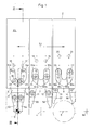
- the transfer device essentially consists of a transfer carrier 2 with gripper devices 6, 7 and 8.
- the gripper devices 6, 7 and 8 each have gripper fingers 9, 10 or 11, 12 or 13, 14 assigned to one another in pairs on.
- the gripper devices 6, 7 and 8 attached to the transfer carrier 2 are moved in a manner known per se - and similarly as described for example in German Offenlegungsschrift 35 23 323 - in the sense of arrow 52 in FIG. 1 so that the free ends of the inserts 53 to 58 attached to the gripper fingers 9 to 14 are moved back and forth in a manner known per se between pick-up and discharge positions 3, 4, 5 and 59. This back and forth movement takes place in an imaginary transfer plane, designated 15 (see FIG. 2).
- the gripper fingers 9 to 14 are via corresponding bearing bores, e.g. Bearing bore 40 for the gripper fingers 10 (see FIG. 2), pivotably mounted on pivot pins 16, 17 or 18, 19 or 20, 21, which pivot pins form the first supports for the gripper fingers.
- the pivot pins 16 to 21 are located on extensions of plungers which are under the action of compression springs, for example extension 41 on the plunger 42 with compression spring 43 (see FIG. 2).
- the gripper fingers 9 to 14 have pins 22 to 27.
- the pins 22 to 27 each carry one of rollers 28 to 33.
- the rollers 28 to 33 run on slides 34a, 34b or 35a, 35b or 36a, 36b, which slides each represent the second supports for the gripper fingers 9 to 14.
- compression springs 37, 38 and 39 are provided, which cause the rollers 28 to 33 of the associated gripper finger pairs always with sufficient pressure on each associated backdrop 34a to 36b.
- the plungers for the gripper fingers are movably guided in the direction of arrow 62 between upper and lower guide bushes, for example guide bushes 60 and 61 for the plunger 42.
- a two-armed lever is provided as a control element for the plunger, which is pivotally mounted in a known manner on the transfer carrier as shown in FIG Machine clock moving ruler 50 is controlled, as is known from the prior art.
- the lever 4 is provided for the plunger 42 as a control element, one arm 45 of which engages with its free end in a recess 46 of the plunger 42 and rests there against a pressure surface 47 against the action of the compression spring 43.
- the other, designated 48 arm of the lever 44 has at its free end a roller 49, via which the lever 44 is controlled by the ruler 50 approximately in the direction of arrow 63 in the machine cycle.
- the ruler 50 is located at the free end of a lever 51 (not shown), which is pivotably mounted and driven in the machine frame. This known construction enables the movement of the transfer carrier 2 to be superimposed on the gripper devices 6 to 8 in the direction of the arrow 52 with the control movements of the lever 51 in the direction of the arrow 63.
- pin-shaped path scanners are used instead of rollers for scanning the scenes or curves. It is possible that the cam tracks are provided in the gripper fingers and that the pin-shaped track scanners are mounted on the transfer carrier.
- cam tracks can also be provided on the side of the gripper fingers.
- the gripper fingers are at least up to the region of the second supports on both sides in a correspondingly fork-shaped end of the transfer carrier - in the case of the exemplary embodiment between the guide plates 63 and 64 - in each case to the transfer plane 15 parallel plane.
- the arrangement can also be such that a separate compression spring is provided for the two gripper fingers of a pair of gripper fingers, one of which Ends as in the exemplary embodiment on the gripper fingers and their other ends are supported on a stop mounted on the guide plates 63, 64, which can follow the movements of the gripper fingers in the direction of arrow 62.
Abstract
Description
Die Erfindung betrifft eine Überführungsvorrichtung entsprechend dem Oberbegriff des Patentanspruches 1. Eine Überführungsvorrichtung dieser Art ist in der deutschen Offenlegungsschrift 35 23 323 beschrieben.The invention relates to a transfer device according to the preamble of
Der Vorteil der in der erwähnten Druckschrift gezeigten und erläuterten Konstruktion gegenüber älteren Konstruktionen von derartigen Überführungsvorrichtungen besteht darin, daß infolge der Überlagerung einer linearen Antriebsbewegung für die Greiferfinger mit einer Schwenkbewegung der Greiferfinger eine Bewegungsbahn der freien Enden der Greiferfinger erzielbar ist, die das gewünschte schnelle und weite Öffnen und ein gewünschtes, genügend weites Entfernen des Greifers vom betreffenden Werkzeug der Umformmaschine bewirkt.The advantage of the construction shown and explained in the mentioned publication compared to older constructions of such transfer devices is that, due to the superimposition of a linear drive movement for the gripper fingers with a pivoting movement of the gripper fingers, a movement path of the free ends of the gripper fingers can be achieved which achieves the desired fast and wide opening and a desired, sufficient removal of the gripper from the relevant tool of the forming machine.
Nachteilig bei der Konstruktion nach der deutschen Offenlegungsschrift 35 23 323 ist die Tatsache, daß die Schwenkbewegung der Greiferfinger in Abhängigkeit von der senkrecht zur Überführungsrichtung erfolgenden Bewegung der Greiferfinger wegen der dort vorgesehenen Lenkerkonstruktion starr vorgegeben ist. Ein in seiner Struktur fest vorgegebenes Bewegungsgesetz für die Greiferfinger ist keineswegs in allen Anwendungsfällen an Umformmaschinen oder Mehrstufenpressen die angestrebte optimale Lösung für den Bewegungsablauf des Greifers oder der Greifer.A disadvantage of the construction according to German Offenlegungsschrift 35 23 323 is the fact that the pivoting movement of the gripper fingers depends on the movement of the movement perpendicular to the direction of transfer Gripper finger is rigidly specified because of the handlebar design provided there. A movement law for the gripper fingers that is fixed in its structure is by no means the desired solution for the movement sequence of the gripper or the grippers in all applications on forming machines or multi-stage presses.
Der vorliegenden Erfindung liegt die Aufgabe zugrunde, bei einer Überführungsvorrichtung der eingangs genannten Art die Möglichkeit zu schaffen, das Bewegungsgesetz für die Greiferfinger den individuellen Erfordernissen entsprechend optimal anpassen zu können. Diese Aufgabe wird mit dem im kennzeichnenden Teil des Anspruches 1 angegebenen Merkmal gelöst.The present invention has for its object to provide in a transfer device of the type mentioned, the possibility of optimally adapting the law of movement for the gripper fingers according to individual requirements. This object is achieved with the feature specified in the characterizing part of
Ein weiterer Nachteil der Lösung nach der deutschen Offenlegungsschrift 35 23 323 besteht darin, daß die lediglich am einen Ende schwenkbar und von diesem Ende aus etwa quer zur Überführungsrichtung bewegbar gehaltenen, langgestreckten Greiferfinger keinerlei weitere Führungsmittel aufweisen, so daß insbesondere gewisse unkontrollierte oder unkontrollierbare Bewegungen oder Auslenkungen der Greiferfinger quer zu deren Schwenkebene möglich sind. Die hieraus resultierenden Probleme bei der Werkstückaufnahme und -abgabe können - neben einem im Hinblick auf die Art der jeweiligen Werkstücke und der zum Umformen verwendeten Werkzeuge ungeeigneten Bewegungsgesetz für die Greifer - die Leistungsfähigkeit einer Umformmaschine oder Mehrstufenpresse erheblich mindern. Deshalb ist für eine sichere Führung der Greiferfinger in der Schwenkebene zu sorgen, so daß auch bei relativ hohen Arbeitstakten an der Umformmaschine oder Mehrstufenpresse sichere und präzise Aufnahme und Abgabe der Werkstücke an den betreffenden Werkzeugen bzw. an die betreffenden Werkzeuge gewährleistet ist. Diese kann mit einer Lösung gemäß Anspruch 10 erreicht werden.Another disadvantage of the solution according to German Offenlegungsschrift 35 23 323 is that the elongated gripper fingers, which can only be pivoted at one end and are movable from this end approximately at right angles to the transfer direction, have no further guide means, so that in particular certain uncontrolled or uncontrollable movements or Deflections of the gripper fingers transversely to their swivel plane are possible. The resulting problems in workpiece pick-up and delivery can - in addition to a motion law for the gripper that is unsuitable with regard to the type of the respective workpiece and the tools used for forming - significantly reduce the performance of a forming machine or multi-stage press. Therefore, it must be ensured that the gripper fingers are guided securely in the swivel plane, so that even with relatively high work cycles on the forming machine or multi-stage press, safe and precise pick-up and delivery of the workpieces on the relevant tools or on the relevant tools is ensured. These can be achieved with a solution according to
In den Ansprüchen 2 bis 9 sowie 11 und 12 sind weitere vorteilhafte oder zweckmäßige Ausgestaltungen der erfindungsgemäßen Überführungsvorrichtung angegeben.
Anhand der Figuren 1 und 2 der Zeichnung wird die Erfindung im folgenden an einem Ausführungsbeispiel weiter erläutert.The invention is explained in more detail below using an exemplary embodiment with reference to FIGS. 1 and 2 of the drawing.
- Figur 1Figure 1
- eine erfindungsgemäße Überführungsvorrichtung in der Vorderansicht, und a transfer device according to the invention in front view, and
- Figur 2Figure 2
- die Überführungsvorrichtung nach Figur 1 in der Seitenansicht im Schnitt entsprechend Schnittlinie II-II in Figur 1. the transfer device of Figure 1 in side view in section along section line II-II in Figure 1.
Die in der Zeichnung allgemein mit 1 bezeichnete Überführungsvorrichtung besteht im wesentlichen aus einem Überführungsträger 2 mit Greifervorrichtungen 6, 7 und 8. Die Greifervorrichtungen 6, 7 und 8 weisen jeweils einander paarweise zugeordnete Greiferfinger 9, 10 bzw. 11, 12 bzw. 13, 14 auf. Die am Überführungsträger 2 befestigten Greifervorrichtungen 6, 7 und 8 werden auf an sich bekannte Weise - und ähnlich wie beispielsweise in der deutschen Offenlegungsschrift 35 23 323 beschrieben - im Sinne des Pfeiles 52 in Figur 1 hin- und herbewegt, so daß die freien Enden der an den Greiferfingern 9 bis 14 befestigten Einsätze 53 bis 58 in an sich bekannter Weise zwischen Aufnahme- und Abgabepositionen 3, 4, 5 und 59 hin- und herbewegt werden. Diese Hin- und Herbewegung vollzieht sich in einer gedachten, mit 15 bezeichneten Überführungsebene (s. Figur 2).The transfer device, generally designated 1 in the drawing, essentially consists of a
Die Greiferfinger 9 bis 14 sind über entsprechende Lagerbohrungen, z.B. Lagerbohrung 40 für den Greiferfinger 10 (s. Figur 2), auf Gelenkzapfen 16, 17 bzw. 18, 19 bzw. 20, 21 schwenkbar gelagert, welche Gelenkzapfen die ersten Abstützungen für die Greiferfinger bilden. Die Gelenkzapfen 16 bis 21 befinden sich an Fortsätzen von Stößeln, die unter der Wirkung von Druckfedern stehen, so beispielsweise Fortsatz 41 am Stößel 42 mit Druckfeder 43 (s. Figur 2).The
Ferner weisen die Greiferfinger 9 bis 14 Zapfen 22 bis 27 auf. Die Zapfen 22 bis 27 tragen jeweils eine von Laufrollen 28 bis 33. Die Laufrollen 28 bis 33 laufen auf Kulissen 34a, 34b bzw. 35a, 35b bzw. 36a, 36b, welche Kulissen jeweils die zweiten Abstützungen für die Greiferfinger 9 bis 14 darstellen. - Zwischen den Greiferfinger-Paaren 9, 10 bzw. 11, 12 bzw. 13, 14 sind Druckfedern 37, 38 bzw. 39 vorgesehen, die bewirken, daß die Laufrollen 28 bis 33 der zugehörigen Greiferfinger-Paare stets mit genügendem Druck an der jeweils zugehörigen Kulisse 34a bis 36b anliegen. - Im Hinblick auf einen möglichst hohen Arbeitstakt der Umformmaschine oder Mehrstufenpresse ist es aus ohne weiteres verständlichen Gründen außerdem zweckmäßig, wenn den Kulissen 34a bis 36b in Bezug auf den Ablauf der Laufrollen 28 bis 33 funktionsmäßig parallel verlaufende Führungsflächen - selbstverständlich mit einem gewissen, geringfügigen Abstand zu den Rollen 28 bis 33 - zugeordnet sind. Solche Führungsflächen sind in der Zeichnung mit 64a, 64b, 65a, 65b, 66a und 66b bezeichnet.Furthermore, the
Die Stößel für die Greiferfinger sind zwischen oberen und unteren Führungsbuchsen, so beispielsweise Führungsbuchsen 60 und 61 für den Stößel 42, in Richtung des Pfeiles 62 bewegbar geführt. Zur Steuerung der Stößel in Richtung des Pfeiles 62 ist als Steurelement für die Stößel je ein zweiarmiger Hebel vorgesehen, der in an sich bekannter Weise am Überführungsträger wie in Figur 2 dargestellt schwenkbar gelagert ist und auf ebenfalls an sich bekannte Weise über eine Rolle von einem im Maschinentakt bewegten Lineal 50 gesteuert wird, wie es aus dem Stand der Technik an sich bekannt ist. Beispielsweise ist für den Stößel 42 als Steuerelement der Hebel 4 vorgesehen, dessen einer Arm 45 mit seinem freien Ende in einer Ausnehmung 46 des Stößels 42 eingreift und dort an einer Druckfläche 47 entgegen der Wirkung der Druckfeder 43 anliegt. Der andere, mit 48 bezeichnete Arm des Hebels 44 weist an seinem freien Ende eine Rolle 49 auf, über die der Hebel 44 von dem Lineal 50 etwa in Richtung des Pfeiles 63 im Maschinentakt gesteuert wird. Das Lineal 50 befindet sich am freien Ende eines im übrigen nicht weiter dargestellten Hebels 51, der im Maschinenrahmen entsprechend schwenkbar gelagert und angetrieben ist. Diese bekannte Konstruktion ermöglicht die Überlagerung der Bewegung des Überführungsträgers 2 mit den Greifervorrichtungen 6 bis 8 in Richtung des Pfeiles 52 mit den Steuerbewegungen des Hebels 51 in Richtung des Pfeiles 63.The plungers for the gripper fingers are movably guided in the direction of
Aus der Darstellung der Zeichnung ist ohne weiteres zu entnehmen, daß sich bei entsprechender Steuerung der Stößel für die Greiferfinger diese mit der ihnen jeweils zugeordneten Laufrolle 28 bis 33 entlang der Kulisse 34a, 34b bzw. 35a, 35b bzw. 36a, 36b bewegen. An dieser Stelle sei darauf hingewiesen, daß anstelle der in der Zeichnung dargestellten Lösung für den Kurvenverlauf der Kulissen selbstverständlich in einem entsprechenden Anwendungsfall auch als spezielle Lösung ein kreisbogenförmiger bzw. halbkreisbogenförmiger Kurvenverlauf für die Kulisse sinnvoll sein kann. Im übrigen braucht die Kulisse nicht - wie in der Zeichnung dargestellt - spiegelbildlich gleich ausgeführt zu sein, sondern die Kulisse für die Rolle des einen Greiferfingers eines Greiferfinger-Paares kann einen von der Kulisse für die Rolle des anderen Greiferfingers desselben Greiferfinger-Paares spiegelbildlich abweichenden Verlauf haben.From the illustration of the drawing it can easily be seen that, with appropriate control of the plunger for the gripper fingers, they move with the
Weiterhin ist es möglich, anstelle einer Kulisse wie im Ausführungsbeispiel einen entsprechenden Kulissenstein vorzusehen, an dem die Rollen der Greiferfinger von außen her laufen.Furthermore, it is possible to provide a corresponding sliding block instead of a backdrop, as in the exemplary embodiment, on which the rollers of the gripper fingers run from the outside.
Weiterhin ist eine Lösung denkbar, bei der anstelle von Rollen zum Abtasten der Kulissen oder Kurven stiftförmige Bahnabtaster verwendet werden. Dabei ist es möglich, daß die Kurvenbahnen in den Greiferfingern vorgesehen sind, und daß die stiftförmigen Bahnabtaster am Überführungsträger gelagert sind.Furthermore, a solution is conceivable in which pin-shaped path scanners are used instead of rollers for scanning the scenes or curves. It is possible that the cam tracks are provided in the gripper fingers and that the pin-shaped track scanners are mounted on the transfer carrier.
Außer in den Greiferfingern können die Kurvenbahnen auch seitlich an den Greiferfingern vorgesehen sein. Umgekehrt ist es auch möglich, die Kurvenbahnen am Überführungsträger vorzusehen und die Greiferfinger mit entsprechenden Bahnabtastern zu versehen.In addition to the gripper fingers, the cam tracks can also be provided on the side of the gripper fingers. Conversely, it is also possible to provide the cam tracks on the transfer carrier and to provide the gripper fingers with appropriate track scanners.
Abgesehen von der grundsätzlich gegebenen Möglichkeit, die Kurvenbahnen spiegelbildlich gleich oder ungleich auszubilden und ihnen neben einem als Sonderfall möglichen kreisbogenförmigen bzw. halbkreisbogenförmigen Verlauf einen hiervon mehr oder weniger abweichenden Verlauf zu geben, ist es im Hinblick auf ein möglichst breites Anwendungsspektrum der Erfindung vorteilhaft, die Kurvenbahnen - in welcher Form auch immer - als auswechselbaren Einsatz auszubilden.Apart from the fundamentally given possibility of making the cam tracks mirror-image identical or unequal and, in addition to a circular or semicircular curve which is possible as a special case, to give them a more or less deviating course, it is as wide as possible Application spectrum of the invention advantageous to design the cam tracks - in whatever form - as an interchangeable insert.
Zum störungsfreien Betrieb der betreffenden Maschine, ist es weiterhin dienlich, wenn sich die Greiferfinger zumindest bis in den Bereich der zweiten Abstützungen beidseitig in einem entsprechend gabelförmig ausgebildeten Ende des Überführungsträgers - im Fall des Ausführungsbeispiels zwischen den Führungsplatten 63 und 64 - je in einer zur Überführungsebene 15 parallelen Ebene führen.For trouble-free operation of the machine in question, it is also useful if the gripper fingers are at least up to the region of the second supports on both sides in a correspondingly fork-shaped end of the transfer carrier - in the case of the exemplary embodiment between the
Außer der im Ausführungsbeispiel gezeigten Lösung, nur eine einzige Feder, nämlich die Druckfeder 37, 38 bzw. 39 zu verwenden, kann die Anordnung auch so getroffen werden, daß jeweils eine gesonderte Druckfeder für die beiden Greiferfinger eines Greiferfinger-Paares vorgesehen ist, deren eine Enden sich wie im Ausführungsbeispiel am Greiferfinger und deren andere Enden sich an einem an den Führungsplatten 63. 64 gelagerten Anschlag abstützen, der den Bewegungen der Greiferfinger in Richtung des Pfeiles 62 folgen kann.In addition to the solution shown in the exemplary embodiment, to use only a single spring, namely the
Claims (12)
und
gekennzeichnet durch folgendes Merkmal:
and
characterized by the following feature:
Applications Claiming Priority (2)
| Application Number | Priority Date | Filing Date | Title |
|---|---|---|---|
| DE4002347 | 1990-01-26 | ||
| DE4002347A DE4002347B4 (en) | 1990-01-26 | 1990-01-26 | Transfer device on machines for the progressive molding of workpieces, in particular cross conveyor on multi-stage presses |
Publications (3)
| Publication Number | Publication Date |
|---|---|
| EP0439120A2 true EP0439120A2 (en) | 1991-07-31 |
| EP0439120A3 EP0439120A3 (en) | 1992-03-18 |
| EP0439120B1 EP0439120B1 (en) | 1997-07-16 |
Family
ID=6398869
Family Applications (1)
| Application Number | Title | Priority Date | Filing Date |
|---|---|---|---|
| EP91100760A Expired - Lifetime EP0439120B1 (en) | 1990-01-26 | 1991-01-22 | Transfer device in machines for the progressive forming of workpieces, in particular cross-transfer device in multistage presses |
Country Status (6)
| Country | Link |
|---|---|
| EP (1) | EP0439120B1 (en) |
| JP (1) | JPH05104471A (en) |
| AT (1) | ATE155375T1 (en) |
| CZ (1) | CZ280142B6 (en) |
| DE (2) | DE4002347B4 (en) |
| SK (1) | SK278693B6 (en) |
Cited By (4)
| Publication number | Priority date | Publication date | Assignee | Title |
|---|---|---|---|---|
| EP0623408A1 (en) * | 1993-03-05 | 1994-11-09 | CHIAVETTE UNIFICATE S.p.A. | Method and apparatus for manufacturing a metal element |
| WO2003080875A2 (en) * | 2002-03-26 | 2003-10-02 | Nedschroef Herentals N.V. | Device for transferring wire pieces |
| CN104226881A (en) * | 2013-06-21 | 2014-12-24 | 江苏天工工具有限公司 | Ingot gripper |
| CN107398920A (en) * | 2017-09-12 | 2017-11-28 | 北京京东尚科信息技术有限公司 | Clip claw mechanism and mechanical arm |
Families Citing this family (5)
| Publication number | Priority date | Publication date | Assignee | Title |
|---|---|---|---|---|
| DE10014851C1 (en) * | 2000-03-24 | 2001-09-27 | Wafios Ag | Gripper pair, especially for transverse conveyor device at multistage press for symmetrical work pieces of different diameter, has fingers forming equilateral triangle space for work piece |
| DE10208720B4 (en) | 2002-02-28 | 2005-11-03 | Wafios Ag | Stamp-side ejection device for workpieces in single or multi-stage presses |
| DE102017108928B4 (en) * | 2017-04-26 | 2022-10-27 | Khs Gmbh | container gripper |
| DE102017108926B4 (en) * | 2017-04-26 | 2023-08-03 | Khs Gmbh | Device for transporting containers |
| DE102022123476A1 (en) * | 2022-09-14 | 2024-03-14 | Cevotec Gmbh | Device for gripping a flat structure with openings in the area of its top |
Citations (7)
| Publication number | Priority date | Publication date | Assignee | Title |
|---|---|---|---|---|
| FR1179823A (en) * | 1957-07-24 | 1959-05-28 | Renault | Metal parts extraction pliers with symmetrical closure |
| DE2002987A1 (en) * | 1969-01-28 | 1970-07-30 | Gulf & Western Ind Prod Co | Device for handling workpieces and the like, especially for automatic operating systems |
| FR2278419A1 (en) * | 1974-07-18 | 1976-02-13 | Hatebur Umformmaschinen Ag | AUTOMATIC TRANSVERSAL CONVEYOR FOR MULTI-STAGE FORMING PRESSES |
| JPS543759A (en) * | 1977-06-10 | 1979-01-12 | Hitachi Ltd | Machine hand |
| DE3523323A1 (en) * | 1984-06-29 | 1986-01-02 | The National Machinery Co., Tiffin, Ohio | Transfer device for forming machines and the like |
| EP0245694A1 (en) * | 1986-05-10 | 1987-11-19 | L. SCHULER GmbH | Transporting equipment for work pieces in multistage forming presses |
| DE3704939A1 (en) * | 1987-02-17 | 1988-08-25 | Erhard Otte | Mechanical gripper |
Family Cites Families (1)
| Publication number | Priority date | Publication date | Assignee | Title |
|---|---|---|---|---|
| JPS6478781A (en) * | 1987-09-19 | 1989-03-24 | Nissan Motor | Robot hand |
-
1990
- 1990-01-26 DE DE4002347A patent/DE4002347B4/en not_active Expired - Lifetime
-
1991
- 1991-01-22 AT AT91100760T patent/ATE155375T1/en active
- 1991-01-22 EP EP91100760A patent/EP0439120B1/en not_active Expired - Lifetime
- 1991-01-22 DE DE59108775T patent/DE59108775D1/en not_active Expired - Fee Related
- 1991-01-25 CZ CS91166A patent/CZ280142B6/en not_active IP Right Cessation
- 1991-01-25 SK SK166-91A patent/SK278693B6/en not_active IP Right Cessation
- 1991-01-28 JP JP3087176A patent/JPH05104471A/en active Pending
Patent Citations (7)
| Publication number | Priority date | Publication date | Assignee | Title |
|---|---|---|---|---|
| FR1179823A (en) * | 1957-07-24 | 1959-05-28 | Renault | Metal parts extraction pliers with symmetrical closure |
| DE2002987A1 (en) * | 1969-01-28 | 1970-07-30 | Gulf & Western Ind Prod Co | Device for handling workpieces and the like, especially for automatic operating systems |
| FR2278419A1 (en) * | 1974-07-18 | 1976-02-13 | Hatebur Umformmaschinen Ag | AUTOMATIC TRANSVERSAL CONVEYOR FOR MULTI-STAGE FORMING PRESSES |
| JPS543759A (en) * | 1977-06-10 | 1979-01-12 | Hitachi Ltd | Machine hand |
| DE3523323A1 (en) * | 1984-06-29 | 1986-01-02 | The National Machinery Co., Tiffin, Ohio | Transfer device for forming machines and the like |
| EP0245694A1 (en) * | 1986-05-10 | 1987-11-19 | L. SCHULER GmbH | Transporting equipment for work pieces in multistage forming presses |
| DE3704939A1 (en) * | 1987-02-17 | 1988-08-25 | Erhard Otte | Mechanical gripper |
Non-Patent Citations (1)
| Title |
|---|
| PATENT ABSTRACTS OF JAPAN vol. 3, no. 29 (M-51)10. März 1979 & JP-A-54 003 759 ( HITACHI SEISAKUSHO K.K. ) 1. Dezember 1979 * |
Cited By (6)
| Publication number | Priority date | Publication date | Assignee | Title |
|---|---|---|---|---|
| EP0623408A1 (en) * | 1993-03-05 | 1994-11-09 | CHIAVETTE UNIFICATE S.p.A. | Method and apparatus for manufacturing a metal element |
| WO2003080875A2 (en) * | 2002-03-26 | 2003-10-02 | Nedschroef Herentals N.V. | Device for transferring wire pieces |
| WO2003080875A3 (en) * | 2002-03-26 | 2004-11-25 | Nedschroef Herentals N V | Device for transferring wire pieces |
| CN104226881A (en) * | 2013-06-21 | 2014-12-24 | 江苏天工工具有限公司 | Ingot gripper |
| CN107398920A (en) * | 2017-09-12 | 2017-11-28 | 北京京东尚科信息技术有限公司 | Clip claw mechanism and mechanical arm |
| CN107398920B (en) * | 2017-09-12 | 2024-04-05 | 北京京东乾石科技有限公司 | Clamping jaw mechanism and mechanical arm |
Also Published As
| Publication number | Publication date |
|---|---|
| SK278693B6 (en) | 1998-01-14 |
| JPH05104471A (en) | 1993-04-27 |
| DE59108775D1 (en) | 1997-08-21 |
| CZ280142B6 (en) | 1995-11-15 |
| DE4002347B4 (en) | 2006-06-08 |
| DE4002347A1 (en) | 1991-09-19 |
| CS9100166A2 (en) | 1991-08-13 |
| EP0439120B1 (en) | 1997-07-16 |
| EP0439120A3 (en) | 1992-03-18 |
| ATE155375T1 (en) | 1997-08-15 |
Similar Documents
| Publication | Publication Date | Title |
|---|---|---|
| DE2937061C2 (en) | Handling device with a gripping device | |
| DE3050967C2 (en) | ||
| DE3534428C2 (en) | ||
| EP0799329B1 (en) | Conveyor device for vertically guiding plate-like objects for chemical or electrolytic surface-treatment | |
| DE2708457C2 (en) | Transport mechanism for forging machines | |
| EP1119507A1 (en) | Device for receiving and transporting objects | |
| DE3725310A1 (en) | MECHANICAL REPLACEMENT | |
| DE69832426T2 (en) | Pressing device for sheet metal | |
| DE4002347B4 (en) | Transfer device on machines for the progressive molding of workpieces, in particular cross conveyor on multi-stage presses | |
| EP2314393B1 (en) | Press with tool changing device | |
| DE3102766C2 (en) | Metal band saw | |
| DE102006003522A1 (en) | Three-lever transfer system for workpieces, used in line of production presses, includes rotary lever raised at pivotal point and connected to swinging lever on carriage block | |
| DE3832865C1 (en) | Assembly station having a duplex conveyor | |
| EP0249946B1 (en) | Method and device for the fabrication of a spacing frame for insulating glass panes | |
| EP1748855B1 (en) | Device for the stepped displacement of workpieces | |
| CH673831A5 (en) | ||
| DE2516946C3 (en) | Drive device for a sheet insert | |
| DD229325A5 (en) | COMPACTING DEVICE FOR USE IN A FOUNDRY EQUIPMENT | |
| EP3566959B1 (en) | Packaging machine with compensating cylinder | |
| DE3040655A1 (en) | Feed and discharge attachment for presses etc. - has crank arm drive shaft driven by servomotor, and has guide member at free end of parallelogram lever extension | |
| DE3607904A1 (en) | Adhesive binding machine | |
| EP2274114B1 (en) | Transporting apparatus with positioning stop | |
| DE3339963C2 (en) | ||
| EP0236688A2 (en) | Process for changing electrical conductors when mounting electrical connectors, and apparatus for carrying out the process | |
| DE19755338C2 (en) | Feeding device and feeding method for plate-shaped workpieces |
Legal Events
| Date | Code | Title | Description |
|---|---|---|---|
| PUAI | Public reference made under article 153(3) epc to a published international application that has entered the european phase |
Free format text: ORIGINAL CODE: 0009012 |
|
| AK | Designated contracting states |
Kind code of ref document: A2 Designated state(s): AT BE CH DE DK ES FR GB GR IT LI LU NL SE |
|
| PUAL | Search report despatched |
Free format text: ORIGINAL CODE: 0009013 |
|
| AK | Designated contracting states |
Kind code of ref document: A3 Designated state(s): AT BE CH DE DK ES FR GB GR IT LI LU NL SE |
|
| 17P | Request for examination filed |
Effective date: 19920828 |
|
| 17Q | First examination report despatched |
Effective date: 19931109 |
|
| GRAG | Despatch of communication of intention to grant |
Free format text: ORIGINAL CODE: EPIDOS AGRA |
|
| GRAH | Despatch of communication of intention to grant a patent |
Free format text: ORIGINAL CODE: EPIDOS IGRA |
|
| GRAH | Despatch of communication of intention to grant a patent |
Free format text: ORIGINAL CODE: EPIDOS IGRA |
|
| GRAA | (expected) grant |
Free format text: ORIGINAL CODE: 0009210 |
|
| AK | Designated contracting states |
Kind code of ref document: B1 Designated state(s): AT BE CH DE DK ES FR GB GR IT LI LU NL SE |
|
| PG25 | Lapsed in a contracting state [announced via postgrant information from national office to epo] |
Ref country code: NL Free format text: LAPSE BECAUSE OF FAILURE TO SUBMIT A TRANSLATION OF THE DESCRIPTION OR TO PAY THE FEE WITHIN THE PRESCRIBED TIME-LIMIT Effective date: 19970716 Ref country code: GR Free format text: LAPSE BECAUSE OF FAILURE TO SUBMIT A TRANSLATION OF THE DESCRIPTION OR TO PAY THE FEE WITHIN THE PRESCRIBED TIME-LIMIT Effective date: 19970716 Ref country code: DK Effective date: 19970716 Ref country code: ES Free format text: THE PATENT HAS BEEN ANNULLED BY A DECISION OF A NATIONAL AUTHORITY Effective date: 19970716 |
|
| REF | Corresponds to: |
Ref document number: 155375 Country of ref document: AT Date of ref document: 19970815 Kind code of ref document: T |
|
| ET | Fr: translation filed | ||
| REG | Reference to a national code |
Ref country code: CH Ref legal event code: EP Ref country code: CH Ref legal event code: NV Representative=s name: SCHMAUDER & WANN PATENTANWALTSBUERO, INHABER KLAUS |
|
| GBT | Gb: translation of ep patent filed (gb section 77(6)(a)/1977) |
Effective date: 19970716 |
|
| REF | Corresponds to: |
Ref document number: 59108775 Country of ref document: DE Date of ref document: 19970821 |
|
| ITF | It: translation for a ep patent filed |
Owner name: SOCIETA' ITALIANA BREVETTI S.P.A. |
|
| PG25 | Lapsed in a contracting state [announced via postgrant information from national office to epo] |
Ref country code: SE Effective date: 19971016 |
|
| NLV1 | Nl: lapsed or annulled due to failure to fulfill the requirements of art. 29p and 29m of the patents act | ||
| PG25 | Lapsed in a contracting state [announced via postgrant information from national office to epo] |
Ref country code: AT Free format text: LAPSE BECAUSE OF NON-PAYMENT OF DUE FEES Effective date: 19980122 Ref country code: LU Free format text: LAPSE BECAUSE OF NON-PAYMENT OF DUE FEES Effective date: 19980122 |
|
| PLBE | No opposition filed within time limit |
Free format text: ORIGINAL CODE: 0009261 |
|
| STAA | Information on the status of an ep patent application or granted ep patent |
Free format text: STATUS: NO OPPOSITION FILED WITHIN TIME LIMIT |
|
| 26N | No opposition filed | ||
| REG | Reference to a national code |
Ref country code: GB Ref legal event code: IF02 |
|
| PGFP | Annual fee paid to national office [announced via postgrant information from national office to epo] |
Ref country code: DE Payment date: 20090115 Year of fee payment: 19 |
|
| PGFP | Annual fee paid to national office [announced via postgrant information from national office to epo] |
Ref country code: GB Payment date: 20090121 Year of fee payment: 19 Ref country code: CH Payment date: 20090114 Year of fee payment: 19 |
|
| PGFP | Annual fee paid to national office [announced via postgrant information from national office to epo] |
Ref country code: BE Payment date: 20090213 Year of fee payment: 19 |
|
| PGFP | Annual fee paid to national office [announced via postgrant information from national office to epo] |
Ref country code: IT Payment date: 20090127 Year of fee payment: 19 |
|
| PGFP | Annual fee paid to national office [announced via postgrant information from national office to epo] |
Ref country code: FR Payment date: 20090113 Year of fee payment: 19 |
|
| BERE | Be: lapsed |
Owner name: GEBR. *HILGELAND G.M.B.H. & CO. Effective date: 20100131 |
|
| REG | Reference to a national code |
Ref country code: CH Ref legal event code: PL |
|
| GBPC | Gb: european patent ceased through non-payment of renewal fee |
Effective date: 20100122 |
|
| REG | Reference to a national code |
Ref country code: FR Ref legal event code: ST Effective date: 20100930 |
|
| PG25 | Lapsed in a contracting state [announced via postgrant information from national office to epo] |
Ref country code: FR Free format text: LAPSE BECAUSE OF NON-PAYMENT OF DUE FEES Effective date: 20100201 Ref country code: LI Free format text: LAPSE BECAUSE OF NON-PAYMENT OF DUE FEES Effective date: 20100131 Ref country code: CH Free format text: LAPSE BECAUSE OF NON-PAYMENT OF DUE FEES Effective date: 20100131 |
|
| PG25 | Lapsed in a contracting state [announced via postgrant information from national office to epo] |
Ref country code: DE Free format text: LAPSE BECAUSE OF NON-PAYMENT OF DUE FEES Effective date: 20100803 |
|
| PG25 | Lapsed in a contracting state [announced via postgrant information from national office to epo] |
Ref country code: GB Free format text: LAPSE BECAUSE OF NON-PAYMENT OF DUE FEES Effective date: 20100122 |
|
| PG25 | Lapsed in a contracting state [announced via postgrant information from national office to epo] |
Ref country code: BE Free format text: LAPSE BECAUSE OF NON-PAYMENT OF DUE FEES Effective date: 20100131 |
|
| PG25 | Lapsed in a contracting state [announced via postgrant information from national office to epo] |
Ref country code: IT Free format text: LAPSE BECAUSE OF NON-PAYMENT OF DUE FEES Effective date: 20100122 |