EP0438916A1 - Produit en carbure cimenté revêtu et procédé de fabrication - Google Patents
Produit en carbure cimenté revêtu et procédé de fabrication Download PDFInfo
- Publication number
- EP0438916A1 EP0438916A1 EP90314323A EP90314323A EP0438916A1 EP 0438916 A1 EP0438916 A1 EP 0438916A1 EP 90314323 A EP90314323 A EP 90314323A EP 90314323 A EP90314323 A EP 90314323A EP 0438916 A1 EP0438916 A1 EP 0438916A1
- Authority
- EP
- European Patent Office
- Prior art keywords
- binder phase
- phase
- cemented carbide
- alloy
- solid
- Prior art date
- Legal status (The legal status is an assumption and is not a legal conclusion. Google has not performed a legal analysis and makes no representation as to the accuracy of the status listed.)
- Granted
Links
Images

Classifications
-
- C—CHEMISTRY; METALLURGY
- C22—METALLURGY; FERROUS OR NON-FERROUS ALLOYS; TREATMENT OF ALLOYS OR NON-FERROUS METALS
- C22C—ALLOYS
- C22C29/00—Alloys based on carbides, oxides, nitrides, borides, or silicides, e.g. cermets, or other metal compounds, e.g. oxynitrides, sulfides
- C22C29/02—Alloys based on carbides, oxides, nitrides, borides, or silicides, e.g. cermets, or other metal compounds, e.g. oxynitrides, sulfides based on carbides or carbonitrides
- C22C29/06—Alloys based on carbides, oxides, nitrides, borides, or silicides, e.g. cermets, or other metal compounds, e.g. oxynitrides, sulfides based on carbides or carbonitrides based on carbides, but not containing other metal compounds
- C22C29/08—Alloys based on carbides, oxides, nitrides, borides, or silicides, e.g. cermets, or other metal compounds, e.g. oxynitrides, sulfides based on carbides or carbonitrides based on carbides, but not containing other metal compounds based on tungsten carbide
-
- C—CHEMISTRY; METALLURGY
- C23—COATING METALLIC MATERIAL; COATING MATERIAL WITH METALLIC MATERIAL; CHEMICAL SURFACE TREATMENT; DIFFUSION TREATMENT OF METALLIC MATERIAL; COATING BY VACUUM EVAPORATION, BY SPUTTERING, BY ION IMPLANTATION OR BY CHEMICAL VAPOUR DEPOSITION, IN GENERAL; INHIBITING CORROSION OF METALLIC MATERIAL OR INCRUSTATION IN GENERAL
- C23C—COATING METALLIC MATERIAL; COATING MATERIAL WITH METALLIC MATERIAL; SURFACE TREATMENT OF METALLIC MATERIAL BY DIFFUSION INTO THE SURFACE, BY CHEMICAL CONVERSION OR SUBSTITUTION; COATING BY VACUUM EVAPORATION, BY SPUTTERING, BY ION IMPLANTATION OR BY CHEMICAL VAPOUR DEPOSITION, IN GENERAL
- C23C30/00—Coating with metallic material characterised only by the composition of the metallic material, i.e. not characterised by the coating process
- C23C30/005—Coating with metallic material characterised only by the composition of the metallic material, i.e. not characterised by the coating process on hard metal substrates
-
- B—PERFORMING OPERATIONS; TRANSPORTING
- B22—CASTING; POWDER METALLURGY
- B22F—WORKING METALLIC POWDER; MANUFACTURE OF ARTICLES FROM METALLIC POWDER; MAKING METALLIC POWDER; APPARATUS OR DEVICES SPECIALLY ADAPTED FOR METALLIC POWDER
- B22F2998/00—Supplementary information concerning processes or compositions relating to powder metallurgy
-
- Y—GENERAL TAGGING OF NEW TECHNOLOGICAL DEVELOPMENTS; GENERAL TAGGING OF CROSS-SECTIONAL TECHNOLOGIES SPANNING OVER SEVERAL SECTIONS OF THE IPC; TECHNICAL SUBJECTS COVERED BY FORMER USPC CROSS-REFERENCE ART COLLECTIONS [XRACs] AND DIGESTS
- Y10—TECHNICAL SUBJECTS COVERED BY FORMER USPC
- Y10T—TECHNICAL SUBJECTS COVERED BY FORMER US CLASSIFICATION
- Y10T428/00—Stock material or miscellaneous articles
- Y10T428/12—All metal or with adjacent metals
- Y10T428/12014—All metal or with adjacent metals having metal particles
- Y10T428/12028—Composite; i.e., plural, adjacent, spatially distinct metal components [e.g., layers, etc.]
- Y10T428/12063—Nonparticulate metal component
- Y10T428/1209—Plural particulate metal components
Definitions
- This invention relates to a coated cemented carbide alloy which has good toughness as well as wear resistance and which is used for cutting tools and wear resistant tools.
- a surface-coated cemented carbide comprising a cemented carbide substrate and a thin film such as titanium carbide, coated thereon by vapor-deposition from gaseous phase, has been widely used for cutting tools and wear resistant tools with higher efficiency, as compared with the non-coated cemented carbides of the prior art, because of having both the high toughness of the substrate and the excellent wear resistance of the surface.
- WC-Co alloys As a wear resistance and impact resistance tool, WC-Co alloys have been used and improvement of the wear resistance or toughness thereof has been carried out by controlling the grain size of WC powder and the quantity of Co, in combination.
- the wear resistance and toughness are conflicting properties, so if Co is increased so as to give a high toughness in the above described WC-Co alloy, the wear resistance is lowered.
- Japanese Patent Laid-Open Publication No. 179846/1986 discloses an alloy in which ⁇ phase is allowed to be present in the interior of the alloy and a binder phase is enriched outside it.
- this alloy has disadvantages that because of containing the brittle phase, i.e., ⁇ phase inside, the impact resistance, at which the present invention aims, is lacking and when the quantity of the binder phase is high in this alloy, dimensional deformation tends to occur due to reaction with a packing agent such as alumina.
- the present invention provides a surface-coated cemented carbide comprising a cemented carbide substrate consisting of a hard phrase of at least one carbide, nitride or carbonitride of a Group IVa, Va or VIa metal of the Periodic Tabale and a binder phase consisting of at least one iron group metal, and a monolayer or multilayer provided thereon, consisting of at least one carbide, nitride, oxide or boride of a Group IVa, Va or VIa metal of the Periodic Table, solid solutions thereof or aluminum oxide, in which a binder phase-enriched layer is provided in a space between 0.01 mm and 2 mm below the surface of the substrate.
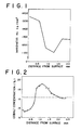
- Fig. 1 is a graph showing the hardness (Hv) distribution of an alloy obtained in Example 5.
- Fig. 2 is a graph showing the Co concentration distribution of an alloy obtained in Example 5.
- Fig. 3 is a graph showing the hardness distribution of alloys M and N obtained in Example 6.
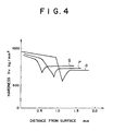
- Fig. 4 is a graph showing the hardness distribution of alloys O, P and Q obtained in Example 7.
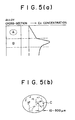
- Fig. 5(a) is a cross-sectional view of one embodiment of the cemented carbide according to the present invention to show the property thereof and Fig. (b) is an enlarged view of a zone A in Fig. 5(a).
- the feature (1) gives an effect of maintaining the toughness of the cemented carbide by the binder phase-enriched layer present beneath the surface.
- this layer is present immediately beneath the binder phase-depleted layer given by the feature (4), i.e., the hardness-increased layer and thus serves to moderate the lowering of the toughness of the latter layer.
- the layer of the feature (1) is preferably in the range of 0.01 to 2 mm, preferably 0.05 to 1.0 mm, since if less than 0.01 mm, the wear resistance of the surface is lowered, while if more than 2 mm, the toughness is not so improved.
- the hardened layer of the feature (4) comprises the lower structure composed of WC phase, the other hard phase containing e.g., a Group IVa compound and a binder phase in a smaller amount than that in the interior of the cemented carbide, surrounded by a line wherein the binder phase is partially enriched in granular forms, as shown by the feature (5), whereby the toughness can further be improved.
- the pores are sometimes not formed in the interior part. Furthermore, the hardness distribution over three zones toward the inside, as shown by the feature (2), is given by the structures of the features (1) and (4).
- the hardness distribution shown in the feature (2) is represented by a hardness change of 10 to 20 kg/mm2 in Zone (a) and a hardness change of 100 to 1000 kg/mm2 in Zone (b). If there is no Zone (a), the wear resistance is lacking and a large tensile stress occurs in the binder phase-enriched zone of the inside.
- a cemented carbide consisting of WC and an iron group metal it is preferable to use a cemented carbide consisting of WC and an iron group metal.
- the cemented carbide consisting of WC and an iron group metal at least one member selected from the group consisting of Ti, Ta, Nb, V, Cr, Mo, Al, B and Si is dissolved in the binder phase in a proportion of 0.01% by weight to the upper limit of the solid solution and there are formed a layer in which the quantity of the binder phase is reduced to be less than the mean quantity of the binder phase in the interior part of the alloy in the outside part of the alloy surface and a layer in which the quantity of the binder phase is increased between the above described layer and the central part of the alloy, whereby a high toughness is given.
- the surface of the cemented carbide is coated with a monolayer or multilayer consisting of at least one member selected from the group consisting of carbides, nitrides, oxides and borides of Group IVa, Va and VIa metals of Periodic Table, solid solutions thereof, and aluminum oxide.
- the cemented carbide substrate of the present invention can be prepared by heating or maintaining a compact or sintered body having a density of 50 to 99.9% by weight in a carburizing atmosphere or carburizing and nitriding atmosphere in a solid phase, in solid-liquid phase or through a solid phase to a solid-liquid phase and then sintering it in the solid-liquid phase.
- the carbon content in the surface of the compact or incompletely sintered body is increased and when only the surface has a carbon content capable of causing a liquid phase, the binder phase is melted in only the surface part.
- the melt of the binder phase passes through gaps in the compact or incompletely sintered body by action of the surface tension or shrinkage of the liquid phase and begins to remove inside. The removing of the melt is stopped when the liquid phase occurs in the interior part of the alloy and the removing space disappears. Consequently, the binder phase is decreased in the alloy surface when the solidification is finished and there is formed the binder phase-enriched layer between the surface layer and the interior part.
- the enrichment of the binder phase begins simultaneously with occurrence of the liquid phase, reaches the maximum when the liquid phase occurs in the interior part of the alloy and then homogenization of the binder phase proceeds with progress of the sintering. Therefore, it is preferable to prepare an incompletely sintered body having A-type or B-type pores in the interior part of the alloy. Up to the present time, such pores or cavity of the alloy have been considered harmful. In the case of a cutting tool, however, it is found that the performance depends on the alloy property at a position of about 1 mm beneath the surface and the toughness of the alloy is not lowered, but rather is improved by the binder phase-enriched layer according to the present invention. The present invention is based on this finding.
- the A-type includes pores with a size of less than 10 ⁇ m and the B-type includes pores with a size of 10 to 25 ⁇ m. preferably, the pores are uniformly dispersed, in particular, in a proportion of at most 5%.
- the pores inside the binder phase-enriched layer can be extinguished by increasing the quantity of the binder phase in the alloy and in cemented carbides consisting of WC and iron group metals, in particular, the hardened distribution in the alloy can be controlled by incorporating Ti, et. in the binder phase.
- a very small amount of Ti, etc. is incorporated in the alloy and causes a liquid phase while forming the corresponding carbide, carbonitride or nitride during the step of carburization or the step of carburization and nitrification.
- the cemented carbide is sintered in vacuo at a temperature of at least the carburization temperature or the carburization and nitrification temperature, the carbide, carbonitride or nitride of Ti is decomposed and dissolved in the liquid phase. That is, the amount of solute atoms dissolved in the binder is increased to decrease the amount of the liquid phase to be generated.
- the quantity of Ti, etc. to be added to the binder phase is in the range of 0.03% by weight to the limit of the solid solution, preferably 0.03 to 0.20% by weight, since if it is less than 0.01%, the effect of the addition is little, while if more than the limit of the solid solution, carbide, nitride or carbonitride grains of Ti, etc. are precipitated in the alloy to be sources of stress concentration, thus resulting in lowering of the strength.
- the carburization atmosphere there are used hydrocarbons, CO and mixed gases thereof with H2 and as the nitriding atmosphere, there are used gases containing nitrogen such as N2 and NH3. If the density of the sintered body is less than 50%, pores are too excessive or large to remove the binder phase, while if more than 99.9%, pores are too small to remove the binder phase melted.
- the range of the depth and width of the binder phase-enriched layer near the alloy surface can be controlled by sintering in a nitriding atmosphere or by processing in a carburizing atmosphere or carburizing and nitriding atmosphere and then temperature-raising in a nitriding atmosphere at a temperature of from the processing temperature to 1450°C. If exceeding 1450°C, homogenization of the binder phase proceeds, which should be avoided.
- the cemented carbide contains N2 in a proportion of 0.00 to 0.10% by weight. If it is more than 0.10%, free carbon is precipitated. This is not preferable.
- the quantity of N2 is preferably at most 0.05%.
- the coating layer is formed by the commonly used CVD or PVD method.
- a power mixture having a composition by weight of WC-5%TiC-5%TaC-10%Co was pressed in an insert with a shape of CNMG 1210408, heated to 1250°C in vacuum, heated at a rate of 1°C/min, 2°C/min and 5°C/min to 1290°C in an atmosphere of CH4 at 0.5 torr and maintained for 30 minutes, thus obtaining Samples A, B and C.
- the resulting alloys each were used as a substrate, coated with an inner layer of 5 ⁇ m Ti and an outer layer of 1 ⁇ m Al2O3 and then subjected to cutting tests under the following conditions.
- Co-enriched layers respectively at a depth of 1.5 mm, 1.0 mm and 0.5 mm beneath the surface and pores of A-type uniformly inside the Co-enriched layers.
- the Co-enriched layer contained Co in an amount of 2 times as much as the interior part, on the average, and the surface layer beneath the surface to the Co-enriched layer had a decreased Co content by 30% on the average.
- a powder mixture having a composition by weight of WC-5%TiC-5%TaC-10%Co was pressed in an insert with a shape of CNMG 1210408, heated to 1250°C in vacuum, heated at a rate of 1°C/min, 2°C/min and 5°C/min to 1290°C in an atmosphere of CH4 at 0.5 torr and maintained for 30 minutes, thus obtaining Samples D, E and F.
- each of the samples was heated to 1350°C in vacuum, maintained for 30 minutes.
- the resulting alloys each were used as a substrate, coated with an inner layer of 5 ⁇ m Ti and an outer layer of 1 ⁇ m Al2O3 and then subjected to cutting tests under the following conditions.
- Co-enriched layers respectively at a depth of 1.5 mm, 1.0 mm and 0.5 mm beneath the surface and pores of A-type uniformly inside the Co-enriched layers.
- the Co-enriched layer contained Co in an amount of 2 times as much as the interior part, on the average, and the surface layer beneath the surface to the Co-enriched layer had a decreased Co content by 30% on the average.
- a compact (CNMG 120408) with an alloy composition of WC-15%TiC-5%TaC-10%Co was previously sintered at 1250°C, 1280°C and 1300°C in vacuum to give respectively a density of 80%, 90% and 95%, heated to 1250°C at a rate of 2°C/min, maintained at 1310°C for 40 minutes in an atmosphere of 10% of CH4 and 90% of N2 at 2 torr and then sintered in vacuum at 1360°C for 30 minutes.
- the depths to the Co-enriched layers were respectively 0.6, 1.2 and 1.8 mm (G, H, I).
- a compact (CNMG 120408) with an alloy composition of WC-15%TiC-5%TaC-10%Co was previously sintered at 1250°C, 1280°C and 1300°C in vacuum to give respectively a density of 80%, 90% and 95%, heated to 1250°C at a rate of 2°C/min, maintained at 1310°C for 40 minutes in an atmosphere of 10% of CH4 and 90% of N2 at 2 torr.
- the depths to the Co-enriched layers were respectively 0.6, 1.2 and 1.8 mm (J, K, L).
- a powder mixture having an alloy composition of WC-15%TiC-5%TaC-11%Co was pressed in an insert with a shape of CNMG 120408, heated to 1290°C in vacuum, maintained for 30 minutes to obtain a sintered body with a density of 99.0% and then maintained in a mixed gas of CH4 and H2 of 1.0 torr for 10 minutes, followed by cooling.
- the resulting alloy was used as a substrate and coated with inner layers of 3 ⁇ m TiC and 2 ⁇ m TiCN and an outer layer of Al2O3 by the ordinary CVD method.
- the Hv hardness distribution (load: 500 g) is shown in Fig. 1 and the Co concentration from the surface, analyzed by EPMA (accelerating voltage 20 KV, sample current 200 A, beam diameter 100 ⁇ m), is shown in Fig. 2.
- a powder mixture having a composition of WC-20%Co-5%Ni containing 0.1% of Ti based on the binder phase was pressed in a predetermined shape, heated from room temperature in vacuum and subjected to temperature raising from 1250°C to 1310°C in an atmosphere of CH4 of 0.1 torr or a mixed gas of 10% of CH4 and 90% of N2 of 5 torr respectively at a rate of 2°C/min.
- temperature raising was stopped at 1310°C, an incomplete sintered body of 99% was obtained.
- the resulting alloy was further heated to 1360°C in vacuum, maintained for 30 minutes and cooled to obtain Samples M and N.
- the hardness distribution (load 500 g) of this alloy is shown in Fig. 3 and the amounts of carbon (TC) and N2 in Samples M and N are shown in the following Table 3.
- the quantity of the binder phase was depleted in the surface layer by 40% as little as in the interior part of the alloy and increased in the binder-enriched layer by 40%.
- a powder mixture having an alloy composition of WC-20%Co-5%Ni containing 0.10% of Ti, 0.5% of Ta or 0.2% of Nb in the binder phase was pressed in a predetermined shape, heated to obtain an incomplete sintered body of 99%, then maintained in a mixed gas of 10% of CH4 and 90% of N2 of 5 torr for 30 minutes, heated at a rate of 5°C/min from 1310°C to 1360°C in N2 at 20 torr and maintained at 1360°C in vacuum.
- the resulting alloys had hardness distributions as shown in Fig. 4 and N2 contents of 0.03%, 0.07% and 0.04% (Sample Nos. 0, P and Q).
- the alloys prepared in Examples 6 and 7, M, N, O, P and Q were subjected to a Charpy impact and toughness test, thus obtaining results as shown in Table 4.
- the ordinary alloy having a hardness of 750 kg/mm2 uniformly through the alloy exhibited a strength of 1.6 kgm/cm2.
- the alloys of M and N, obtained in Example 6, were formed in a predetermined punch shape and subjected to a life test by working SCr 21 in an area reduction of 58% and an extrusion length of 10 mm.
- Samples M and N could further be used with a very small quantity of wearing and hardly meeting with breakage, while the ordinary alloy wore off or broken even after working only 2000 to 5000 workpieces.
- cemented carbides of the present invention cutting tools and wear resisting tools can be obtained which are capable of maintaining excellent wear resistance as well as high toughness even under working conditions with a high efficiency that the prior art cannot achieve.
- cemented carbides, very excellent in toughness and wear resistance can be produced in efficient manner.
Landscapes
- Chemical & Material Sciences (AREA)
- Engineering & Computer Science (AREA)
- Materials Engineering (AREA)
- Mechanical Engineering (AREA)
- Metallurgy (AREA)
- Organic Chemistry (AREA)
- Chemical Kinetics & Catalysis (AREA)
- Powder Metallurgy (AREA)
- Cutting Tools, Boring Holders, And Turrets (AREA)
Applications Claiming Priority (12)
| Application Number | Priority Date | Filing Date | Title |
|---|---|---|---|
| JP34452189 | 1989-12-27 | ||
| JP34452289 | 1989-12-27 | ||
| JP34452189 | 1989-12-27 | ||
| JP34452289 | 1989-12-27 | ||
| JP344522/89 | 1989-12-27 | ||
| JP344521/89 | 1989-12-27 | ||
| JP34450889 | 1989-12-28 | ||
| JP34450889 | 1989-12-28 | ||
| JP344508/89 | 1989-12-28 | ||
| JP412717/90 | 1990-12-21 | ||
| JP41271790 | 1990-12-21 | ||
| JP2412717A JP2762745B2 (ja) | 1989-12-27 | 1990-12-21 | 被覆超硬合金及びその製造法 |
Publications (3)
| Publication Number | Publication Date |
|---|---|
| EP0438916A1 true EP0438916A1 (fr) | 1991-07-31 |
| EP0438916B1 EP0438916B1 (fr) | 1996-02-28 |
| EP0438916B2 EP0438916B2 (fr) | 2000-12-20 |
Family
ID=27480644
Family Applications (1)
| Application Number | Title | Priority Date | Filing Date |
|---|---|---|---|
| EP90314323A Expired - Lifetime EP0438916B2 (fr) | 1989-12-27 | 1990-12-27 | Produit en carbure cimenté revêtu et procédé de fabrication |
Country Status (3)
| Country | Link |
|---|---|
| US (1) | US5181953A (fr) |
| EP (1) | EP0438916B2 (fr) |
| DE (1) | DE69025582T3 (fr) |
Cited By (3)
| Publication number | Priority date | Publication date | Assignee | Title |
|---|---|---|---|---|
| US5413869A (en) * | 1991-11-13 | 1995-05-09 | Sandvik Ab | Cemented carbide body with increased wear resistance |
| US5449547A (en) * | 1993-03-15 | 1995-09-12 | Teikoku Piston Ring Co., Ltd. | Hard coating material, sliding member coated with hard coating material and method for manufacturing sliding member |
| EP1548136A1 (fr) * | 2003-12-15 | 2005-06-29 | Sandvik AB | Plaquette en carbure cémenté et son procédé de fabrication |
Families Citing this family (31)
| Publication number | Priority date | Publication date | Assignee | Title |
|---|---|---|---|---|
| SE9101865D0 (sv) * | 1991-06-17 | 1991-06-17 | Sandvik Ab | Titanbaserad karbonitridlegering med slitstarkt ytskikt |
| DE69222138T2 (de) * | 1991-07-22 | 1998-01-22 | Sumitomo Electric Industries | Diamantverkleidetes hartmaterial und verfahren zu dessen herstellung |
| US5665431A (en) * | 1991-09-03 | 1997-09-09 | Valenite Inc. | Titanium carbonitride coated stratified substrate and cutting inserts made from the same |
| SE505460C2 (sv) * | 1992-07-06 | 1997-09-01 | Sandvik Ab | Verktyg av snabbstål med slitstarkt hölje för skärande bearbetning av metaller |
| EP0635580A4 (fr) * | 1993-02-05 | 1996-02-07 | Sumitomo Electric Industries | Alliage dur fritte renfermant de l'azote. |
| KR0170453B1 (ko) * | 1993-08-16 | 1999-02-18 | 쿠라우찌 노리타카 | 절삭공구용초경합금 및 피복초경합금 |
| US6413628B1 (en) * | 1994-05-12 | 2002-07-02 | Valenite Inc. | Titanium carbonitride coated cemented carbide and cutting inserts made from the same |
| US5955186A (en) * | 1996-10-15 | 1999-09-21 | Kennametal Inc. | Coated cutting insert with A C porosity substrate having non-stratified surface binder enrichment |
| KR100286970B1 (ko) * | 1996-12-16 | 2001-04-16 | 오카야마 노리오 | 초경 합금, 이의 제조방법 및 초경 합금 공구 |
| JP3402146B2 (ja) * | 1997-09-02 | 2003-04-28 | 三菱マテリアル株式会社 | 硬質被覆層がすぐれた密着性を有する表面被覆超硬合金製エンドミル |
| DE19845376C5 (de) * | 1998-07-08 | 2010-05-20 | Widia Gmbh | Hartmetall- oder Cermet-Körper |
| WO2000003047A1 (fr) | 1998-07-08 | 2000-01-20 | Widia Gmbh | Corps en metal dur ou en cermet, et son procede de production |
| US6110603A (en) * | 1998-07-08 | 2000-08-29 | Widia Gmbh | Hard-metal or cermet body, especially for use as a cutting insert |
| US6217992B1 (en) | 1999-05-21 | 2001-04-17 | Kennametal Pc Inc. | Coated cutting insert with a C porosity substrate having non-stratified surface binder enrichment |
| US6638474B2 (en) | 2000-03-24 | 2003-10-28 | Kennametal Inc. | method of making cemented carbide tool |
| MXPA02009350A (es) * | 2000-03-24 | 2003-09-22 | Kennametal Inc | Herramienta de carburo cementado y metodo de realizacion. |
| IL137548A (en) | 2000-07-27 | 2006-08-01 | Cerel Ceramic Technologies Ltd | Wear and thermal resistant material produced from super hard particles bound in a matrix of glassceramic by electrophoretic deposition |
| US6575671B1 (en) | 2000-08-11 | 2003-06-10 | Kennametal Inc. | Chromium-containing cemented tungsten carbide body |
| US6554548B1 (en) | 2000-08-11 | 2003-04-29 | Kennametal Inc. | Chromium-containing cemented carbide body having a surface zone of binder enrichment |
| US6612787B1 (en) | 2000-08-11 | 2003-09-02 | Kennametal Inc. | Chromium-containing cemented tungsten carbide coated cutting insert |
| EP1345868B1 (fr) * | 2000-12-19 | 2014-06-25 | Honda Giken Kogyo Kabushiki Kaisha | Outil de moulage forme d'une matiere composite a gradient, et son procede de realisation |
| SE520253C2 (sv) * | 2000-12-19 | 2003-06-17 | Sandvik Ab | Belagt hårdmetallskär |
| AU2002222612A1 (en) * | 2000-12-19 | 2002-07-01 | Honda Giken Kogyo Kabushiki Kaisha | Machining tool and method of producing the same |
| JP5448300B2 (ja) | 2003-12-15 | 2014-03-19 | サンドビック インテレクチュアル プロパティー アクティエボラーグ | 採鉱及び構造物適用の超硬合金工具、及びその製造方法 |
| GB0903343D0 (en) † | 2009-02-27 | 2009-04-22 | Element Six Holding Gmbh | Hard-metal body with graded microstructure |
| US20120177453A1 (en) | 2009-02-27 | 2012-07-12 | Igor Yuri Konyashin | Hard-metal body |
| US8936750B2 (en) * | 2009-11-19 | 2015-01-20 | University Of Utah Research Foundation | Functionally graded cemented tungsten carbide with engineered hard surface and the method for making the same |
| US9388482B2 (en) | 2009-11-19 | 2016-07-12 | University Of Utah Research Foundation | Functionally graded cemented tungsten carbide with engineered hard surface and the method for making the same |
| KR101640690B1 (ko) * | 2014-12-30 | 2016-07-18 | 한국야금 주식회사 | 인성이 향상된 초경합금 |
| CN105132780B (zh) * | 2015-08-17 | 2017-03-01 | 蓬莱市超硬复合材料有限公司 | 一种高速线材轧机用导卫辊及其制备方法 |
| US11401587B2 (en) * | 2018-04-26 | 2022-08-02 | Sumitomo Electric Industries, Ltd. | Cemented carbide, cutting tool containing the same, and method of manufacturing cemented carbide |
Citations (10)
| Publication number | Priority date | Publication date | Assignee | Title |
|---|---|---|---|---|
| US4097275A (en) * | 1973-07-05 | 1978-06-27 | Erich Horvath | Cemented carbide metal alloy containing auxiliary metal, and process for its manufacture |
| GB2095702A (en) * | 1981-03-27 | 1982-10-06 | Kennametal Inc | Cemented carbides with binder enriched surface |
| US4548786A (en) * | 1983-04-28 | 1985-10-22 | General Electric Company | Coated carbide cutting tool insert |
| EP0246211A2 (fr) * | 1986-05-12 | 1987-11-19 | Santrade Limited | Corps fritté pour le façonnage par enlèvement de copeaux |
| EP0247985A2 (fr) * | 1986-05-12 | 1987-12-02 | Santrade Ltd. | Carbure cémenté dont la phase liante varie d'une façon continue, et son procédé de fabrication |
| US4828612A (en) * | 1987-12-07 | 1989-05-09 | Gte Valenite Corporation | Surface modified cemented carbides |
| US4830930A (en) * | 1987-01-05 | 1989-05-16 | Toshiba Tungaloy Co., Ltd. | Surface-refined sintered alloy body and method for making the same |
| EP0337696A1 (fr) * | 1988-04-12 | 1989-10-18 | Sumitomo Electric Industries, Ltd. | Carbure cémenté enduit en surface |
| EP0344421A1 (fr) * | 1988-05-13 | 1989-12-06 | Toshiba Tungaloy Co. Ltd. | Alliage fritté à surface affinée sans et avec une couche superficielle dure et procédé de production de cet alliage |
| EP0395608A2 (fr) * | 1989-04-24 | 1990-10-31 | Sandvik Aktiebolag | Outil à couper des matériaux solides |
Family Cites Families (5)
| Publication number | Priority date | Publication date | Assignee | Title |
|---|---|---|---|---|
| DD118898A1 (fr) † | 1975-01-29 | 1976-03-20 | ||
| US4318733A (en) * | 1979-11-19 | 1982-03-09 | Marko Materials, Inc. | Tool steels which contain boron and have been processed using a rapid solidification process and method |
| US4497874A (en) * | 1983-04-28 | 1985-02-05 | General Electric Company | Coated carbide cutting tool insert |
| EP0182759B2 (fr) * | 1984-11-13 | 1993-12-15 | Santrade Ltd. | Elément de carbure cémenté à utiliser de préférence pour le forage de roches et la coupe de minéraux |
| US4649084A (en) * | 1985-05-06 | 1987-03-10 | General Electric Company | Process for adhering an oxide coating on a cobalt-enriched zone, and articles made from said process |
-
1990
- 1990-12-27 EP EP90314323A patent/EP0438916B2/fr not_active Expired - Lifetime
- 1990-12-27 DE DE69025582T patent/DE69025582T3/de not_active Expired - Fee Related
- 1990-12-27 US US07/634,549 patent/US5181953A/en not_active Expired - Fee Related
Patent Citations (10)
| Publication number | Priority date | Publication date | Assignee | Title |
|---|---|---|---|---|
| US4097275A (en) * | 1973-07-05 | 1978-06-27 | Erich Horvath | Cemented carbide metal alloy containing auxiliary metal, and process for its manufacture |
| GB2095702A (en) * | 1981-03-27 | 1982-10-06 | Kennametal Inc | Cemented carbides with binder enriched surface |
| US4548786A (en) * | 1983-04-28 | 1985-10-22 | General Electric Company | Coated carbide cutting tool insert |
| EP0246211A2 (fr) * | 1986-05-12 | 1987-11-19 | Santrade Limited | Corps fritté pour le façonnage par enlèvement de copeaux |
| EP0247985A2 (fr) * | 1986-05-12 | 1987-12-02 | Santrade Ltd. | Carbure cémenté dont la phase liante varie d'une façon continue, et son procédé de fabrication |
| US4830930A (en) * | 1987-01-05 | 1989-05-16 | Toshiba Tungaloy Co., Ltd. | Surface-refined sintered alloy body and method for making the same |
| US4828612A (en) * | 1987-12-07 | 1989-05-09 | Gte Valenite Corporation | Surface modified cemented carbides |
| EP0337696A1 (fr) * | 1988-04-12 | 1989-10-18 | Sumitomo Electric Industries, Ltd. | Carbure cémenté enduit en surface |
| EP0344421A1 (fr) * | 1988-05-13 | 1989-12-06 | Toshiba Tungaloy Co. Ltd. | Alliage fritté à surface affinée sans et avec une couche superficielle dure et procédé de production de cet alliage |
| EP0395608A2 (fr) * | 1989-04-24 | 1990-10-31 | Sandvik Aktiebolag | Outil à couper des matériaux solides |
Cited By (3)
| Publication number | Priority date | Publication date | Assignee | Title |
|---|---|---|---|---|
| US5413869A (en) * | 1991-11-13 | 1995-05-09 | Sandvik Ab | Cemented carbide body with increased wear resistance |
| US5449547A (en) * | 1993-03-15 | 1995-09-12 | Teikoku Piston Ring Co., Ltd. | Hard coating material, sliding member coated with hard coating material and method for manufacturing sliding member |
| EP1548136A1 (fr) * | 2003-12-15 | 2005-06-29 | Sandvik AB | Plaquette en carbure cémenté et son procédé de fabrication |
Also Published As
| Publication number | Publication date |
|---|---|
| EP0438916B1 (fr) | 1996-02-28 |
| DE69025582T2 (de) | 1996-07-11 |
| EP0438916B2 (fr) | 2000-12-20 |
| US5181953A (en) | 1993-01-26 |
| DE69025582D1 (de) | 1996-04-04 |
| DE69025582T3 (de) | 2001-05-31 |
Similar Documents
| Publication | Publication Date | Title |
|---|---|---|
| EP0438916B1 (fr) | Produit en carbure cimenté revêtu et procédé de fabrication | |
| US5283030A (en) | Coated cemented carbides and processes for the production of same | |
| CA1319497C (fr) | Carbure metallique a revetement superficiel et procede de production connexe | |
| EP0246211B1 (fr) | Corps fritté pour le façonnage par enlèvement de copeaux | |
| EP1953258B1 (fr) | Outil revêtu d'alpha-alumine à la texture durcie | |
| KR0163654B1 (ko) | 피복경질합금 절삭공구 | |
| US5310605A (en) | Surface-toughened cemented carbide bodies and method of manufacture | |
| JP2684721B2 (ja) | 表面被覆炭化タングステン基超硬合金製切削工具およびその製造法 | |
| EP1528125B1 (fr) | Plaquette revêtue pour dégrossissage | |
| EP1710326A1 (fr) | Outil de coupe a surface enrobee | |
| USRE35538E (en) | Sintered body for chip forming machine | |
| EP0682580A1 (fr) | Carbure cemente avec zone de surface enrichie par la phase liante et tenue de la durete du bord amelioree | |
| GB2419606A (en) | Tugsten alloyed with carbon and optionally fluorine | |
| EP0440157A1 (fr) | Procédé de production d'une lame revêtue pour outils de coupe | |
| EP1352697B1 (fr) | Plaquette pour outil de coupe à revêtement | |
| JP2628200B2 (ja) | TiCN基サーメットおよびその製法 | |
| JPH03115571A (ja) | 付着性にすぐれたダイヤモンド被覆焼結合金及びその製造方法 | |
| JP2771337B2 (ja) | 被覆TiCN基サーメット | |
| JP2003013102A (ja) | 多元系炭窒化物粉末およびその製造方法とそれを原料とする焼結体 | |
| JP2828511B2 (ja) | 表面被覆TiCN基サーメット | |
| JP2771336B2 (ja) | 被覆TiCN基サーメット | |
| CN113453828A (zh) | 硬质皮膜切削工具 | |
| JP2828512B2 (ja) | 被覆TiCN基サーメット | |
| JPH0215622B2 (fr) | ||
| JP2005153099A (ja) | 表面被覆切削工具 |
Legal Events
| Date | Code | Title | Description |
|---|---|---|---|
| PUAI | Public reference made under article 153(3) epc to a published international application that has entered the european phase |
Free format text: ORIGINAL CODE: 0009012 |
|
| AK | Designated contracting states |
Kind code of ref document: A1 Designated state(s): DE FR GB IT SE |
|
| 17P | Request for examination filed |
Effective date: 19910821 |
|
| 17Q | First examination report despatched |
Effective date: 19930818 |
|
| GRAA | (expected) grant |
Free format text: ORIGINAL CODE: 0009210 |
|
| ITF | It: translation for a ep patent filed |
Owner name: BARZANO' E ZANARDO MILANO S.P.A. |
|
| AK | Designated contracting states |
Kind code of ref document: B1 Designated state(s): DE FR GB IT SE |
|
| REF | Corresponds to: |
Ref document number: 69025582 Country of ref document: DE Date of ref document: 19960404 |
|
| ET | Fr: translation filed | ||
| PLBQ | Unpublished change to opponent data |
Free format text: ORIGINAL CODE: EPIDOS OPPO |
|
| PLBI | Opposition filed |
Free format text: ORIGINAL CODE: 0009260 |
|
| 26 | Opposition filed |
Opponent name: SANDVIK AB Effective date: 19961126 |
|
| PLBF | Reply of patent proprietor to notice(s) of opposition |
Free format text: ORIGINAL CODE: EPIDOS OBSO |
|
| PLBF | Reply of patent proprietor to notice(s) of opposition |
Free format text: ORIGINAL CODE: EPIDOS OBSO |
|
| PLBF | Reply of patent proprietor to notice(s) of opposition |
Free format text: ORIGINAL CODE: EPIDOS OBSO |
|
| PGFP | Annual fee paid to national office [announced via postgrant information from national office to epo] |
Ref country code: FR Payment date: 19981209 Year of fee payment: 9 |
|
| REG | Reference to a national code |
Ref country code: GB Ref legal event code: 746 Effective date: 19990928 |
|
| PLAW | Interlocutory decision in opposition |
Free format text: ORIGINAL CODE: EPIDOS IDOP |
|
| PLAW | Interlocutory decision in opposition |
Free format text: ORIGINAL CODE: EPIDOS IDOP |
|
| PG25 | Lapsed in a contracting state [announced via postgrant information from national office to epo] |
Ref country code: FR Free format text: LAPSE BECAUSE OF NON-PAYMENT OF DUE FEES Effective date: 20000831 |
|
| REG | Reference to a national code |
Ref country code: FR Ref legal event code: ST |
|
| PUAH | Patent maintained in amended form |
Free format text: ORIGINAL CODE: 0009272 |
|
| STAA | Information on the status of an ep patent application or granted ep patent |
Free format text: STATUS: PATENT MAINTAINED AS AMENDED |
|
| 27A | Patent maintained in amended form |
Effective date: 20001220 |
|
| AK | Designated contracting states |
Kind code of ref document: B2 Designated state(s): DE FR GB IT SE |
|
| ET3 | Fr: translation filed ** decision concerning opposition | ||
| PGFP | Annual fee paid to national office [announced via postgrant information from national office to epo] |
Ref country code: SE Payment date: 20011206 Year of fee payment: 12 |
|
| PGFP | Annual fee paid to national office [announced via postgrant information from national office to epo] |
Ref country code: GB Payment date: 20011227 Year of fee payment: 12 |
|
| REG | Reference to a national code |
Ref country code: GB Ref legal event code: IF02 |
|
| PGFP | Annual fee paid to national office [announced via postgrant information from national office to epo] |
Ref country code: DE Payment date: 20020109 Year of fee payment: 12 |
|
| PG25 | Lapsed in a contracting state [announced via postgrant information from national office to epo] |
Ref country code: GB Free format text: LAPSE BECAUSE OF NON-PAYMENT OF DUE FEES Effective date: 20021227 |
|
| PG25 | Lapsed in a contracting state [announced via postgrant information from national office to epo] |
Ref country code: SE Free format text: LAPSE BECAUSE OF NON-PAYMENT OF DUE FEES Effective date: 20021228 |
|
| PG25 | Lapsed in a contracting state [announced via postgrant information from national office to epo] |
Ref country code: DE Free format text: LAPSE BECAUSE OF NON-PAYMENT OF DUE FEES Effective date: 20030701 |
|
| EUG | Se: european patent has lapsed | ||
| GBPC | Gb: european patent ceased through non-payment of renewal fee |
Effective date: 20021227 |
|
| PG25 | Lapsed in a contracting state [announced via postgrant information from national office to epo] |
Ref country code: IT Free format text: LAPSE BECAUSE OF NON-PAYMENT OF DUE FEES;WARNING: LAPSES OF ITALIAN PATENTS WITH EFFECTIVE DATE BEFORE 2007 MAY HAVE OCCURRED AT ANY TIME BEFORE 2007. THE CORRECT EFFECTIVE DATE MAY BE DIFFERENT FROM THE ONE RECORDED. Effective date: 20051227 |