EP0437973B1 - Kühlmittelpumpe für einen Reaktor mit hitzebeständiger hydrostatischer Dichtungsanordnung - Google Patents
Kühlmittelpumpe für einen Reaktor mit hitzebeständiger hydrostatischer Dichtungsanordnung Download PDFInfo
- Publication number
- EP0437973B1 EP0437973B1 EP90314214A EP90314214A EP0437973B1 EP 0437973 B1 EP0437973 B1 EP 0437973B1 EP 90314214 A EP90314214 A EP 90314214A EP 90314214 A EP90314214 A EP 90314214A EP 0437973 B1 EP0437973 B1 EP 0437973B1
- Authority
- EP
- European Patent Office
- Prior art keywords
- rib
- annular
- ring
- height
- seal assembly
- Prior art date
- Legal status (The legal status is an assumption and is not a legal conclusion. Google has not performed a legal analysis and makes no representation as to the accuracy of the status listed.)
- Expired - Lifetime
Links
Images


Classifications
-
- G—PHYSICS
- G21—NUCLEAR PHYSICS; NUCLEAR ENGINEERING
- G21D—NUCLEAR POWER PLANT
- G21D1/00—Details of nuclear power plant
- G21D1/04—Pumping arrangements
-
- F—MECHANICAL ENGINEERING; LIGHTING; HEATING; WEAPONS; BLASTING
- F16—ENGINEERING ELEMENTS AND UNITS; GENERAL MEASURES FOR PRODUCING AND MAINTAINING EFFECTIVE FUNCTIONING OF MACHINES OR INSTALLATIONS; THERMAL INSULATION IN GENERAL
- F16J—PISTONS; CYLINDERS; SEALINGS
- F16J15/00—Sealings
- F16J15/16—Sealings between relatively-moving surfaces
- F16J15/34—Sealings between relatively-moving surfaces with slip-ring pressed against a more or less radial face on one member
- F16J15/3404—Sealings between relatively-moving surfaces with slip-ring pressed against a more or less radial face on one member and characterised by parts or details relating to lubrication, cooling or venting of the seal
-
- Y—GENERAL TAGGING OF NEW TECHNOLOGICAL DEVELOPMENTS; GENERAL TAGGING OF CROSS-SECTIONAL TECHNOLOGIES SPANNING OVER SEVERAL SECTIONS OF THE IPC; TECHNICAL SUBJECTS COVERED BY FORMER USPC CROSS-REFERENCE ART COLLECTIONS [XRACs] AND DIGESTS
- Y02—TECHNOLOGIES OR APPLICATIONS FOR MITIGATION OR ADAPTATION AGAINST CLIMATE CHANGE
- Y02E—REDUCTION OF GREENHOUSE GAS [GHG] EMISSIONS, RELATED TO ENERGY GENERATION, TRANSMISSION OR DISTRIBUTION
- Y02E30/00—Energy generation of nuclear origin
Definitions
- the present invention relates generally to shaft seals and, more particularly, is concerned with a thermally stabilized hydrostatic sealing assembly for a reactor coolant pump used in a nuclear power plant.
- a reactor coolant system In pressurized water nuclear power plants, a reactor coolant system is used to transport heat from the reactor core to steam generators for the production of steam. The steam is then used to drive a turbine generator.
- the reactor coolant system includes a plurality of separate cooling loops, each connected to the reactor core and containing a steam generator and a reactor coolant pump.
- the reactor coolant pump typically is a vertical, single stage, centrifugal pump designed to move large volumes of reactor coolant at high temperatures and pressures, for example 287.77 degrees C (550 degrees F) and 170.115 atm (2500 psi).
- the pump basically includes three general sections from bottom to top -- hydraulic, shaft seal and motor sections.
- the lower hydraulic section includes an impeller mounted on the lower end of a pump shaft which is operable within the pump casing to pump reactor coolant about the respective loop.
- the upper motor section includes a motor which is coupled to drive the pump shaft.
- the middle shaft seal section includes three tandem sealing assemblies -- lower primary, middle secondary and upper tertiary sealing assemblies. The sealing assemblies are located concentric to, and near the top end of, the pump shaft.
- Pump shaft sealing assemblies known in the prior art are the ones disclosed in U. S. Patents to MacCrum (3,522,948), Singleton (3,529,838), Villasor (3,632,117), Andrews et al. (3,720,222) and Boes (4,275,891) and in the first three patent applications cross-referenced above, all of which are assigned to the same assignee as the present invention.
- the lower primary sealing assembly is the main seal of the pump. It is typically a hydrostatic, radially tapered "film-riding", controlled-leakage seal whose primary components are an annular runner which rotates with the pump shaft and a non-rotating annular seal ring which is attached to the housing of the lower seal assembly.
- the annular runner typically includes an annular runner faceplate member mounted by a hydrostatic clamp ring member to an annular runner base or support member which, in turn, is keyed to the pump shaft for rotation therewith.
- the annular seal ring typically includes an annular ring faceplate member mounted by a hydrostatic clamp ring member to an annular ring base or support member which, in turn, is keyed to the seal housing so as to prevent rotational movement of the seal ring relative to the seal housing but allow translatory movement of the seal ring along the pump shaft toward and away from the runner which rotates with the pump shaft.
- the pump shaft seals constitute the main problem area for the reactor coolant pumps and significantly contribute to the utilization factor in nuclear power plants.
- the seals must be capable of breaking down the high system pressure (about 170.115 atm) safely.
- the tandem arrangement of three seals is used to break down the pressure
- the lower main seal absorbs most of the pressure drop (approximately 153.104 atm).
- the lower seal Being a hydrostatic "film-riding" seal, the lower seal is designed to "lift off” (separate) at low system pressures by a hydrostatic pressure force present in the gap between the stationary seal ring and the rotating runner.
- a closing or seating force which must balance the lifting force, is produced by the system pressure acting on the surfaces opposite the film surfaces of the seal ring and runner.
- thermally stabilized hydrostatic sealing assembly designed to satisfy the aforementioned needs.
- thermally insulating between the respective faceplate and support members of the seal ring and runner would decrease the ability of the faceplate members to attain detrimental axial temperature gradients and thus would decrease the sensitivity of the seal to inlet water temperature changes.
- the provision of thermal insulative feature is accomplished by undercutting the contact surface of the prior art support members to provide an annular pocket or cavity in areas not necessary to seal function.
- an inlet is provided to the annular insulative cavity for permitting water to fill the cavity and provide a substantially static pool of water which acts as an insulating medium.
- a solid insert of insulative material can be provided in the pocket. The lower thermal diffusivity of the insulated pocket would decrease the ability of the faceplate member to attain an axial thermal gradient.
- the undercutting of the support members to provide a simple method of increasing the thermal stability, coincidentally provides manufacturing, inspection, and operational improvements as well.
- the key to these benefits is that 95% of the seating surface between the faceplate members and their respective bases or support members is non-functional as related to proper seal performance; thus, removal of this non-functional surface eliminates a liability with regard to machining, inspecting, dirt inclusion damage, intermolecular attraction effects, and others.
- the invention consists in a hydrostatic sealing assembly as defined in claim 1.
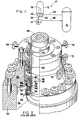
- the cooling loop 10 includes a steam generator 12 and a reactor coolant pump 14 serially connected in a closed coolant flow circuit with a nuclear reactor core 16.
- the steam generator 12 includes primary tubes 18 communicating with inlet and outlet plenums 20,22 of the generator.
- the inlet plenum 20 of the steam generator 12 is connected in flow communication with the outlet of the reactor core 16 for receiving hot coolant therefrom along flow path 24 of the closed flow circuit.
- the outlet plenum 22 of the steam generator 12 is connected in flow communication with an inlet suction side of the reactor coolant pump 14 along flow path 26 of the closed flow circuit.
- the outlet pressure side of the reactor coolant pump 14 is connected in flow communication with the inlet of the reactor core 16 for feeding cold coolant thereto along flow path 28 of the closed flow circuit.
- the coolant pump 14 pumps the coolant under high pressure about the closed flow circuit.
- hot coolant emanating from the reactor core 16 is conducted to the inlet plenum 20 of the steam generator 12 and to the primary tubes 18 in communication therewith. While in the primary tubes 18, the hot coolant flows in heat exchange relationship with cool feedwater supplied to the steam generator 12 via conventional means (not shown).
- the feedwater is heated and portions thereof changed to steam for use in driving a turbine generator (not shown).
- the coolant whose temperature has been reduced by the heat exchange, is then recirculated to the reactor core 16 via the coolant pump 14.
- the reactor coolant pump 14 must be capable of moving large volumes of reactor coolant at high temperatures and pressures about the closed flow circuit. Although, the temperature of the coolant flowing from the steam generator 12 to the pump 14 after heat exchange has been cooled substantially below the temperature of the coolant flowing to the steam generator 12 from the reactor core 16 before heat exchange, its temperature is still relatively high, being typically about 287.77 degrees C (550 degrees F). The coolant pressure produced by the pump is typically about 170.115 atm (2500 psi).
- the prior art reactor coolant pump 14 generally includes a pump housing 30 which terminates at one end in a seal housing 32.
- the pump 14 also includes a pump shaft 34 extending centrally of the housing 30 and being sealingly and rotatably mounted within the seal housing 32.
- the bottom portion of the pump shaft 34 is connected to an impeller, while a top portion thereof is connected to a high-horsepower, induction-type electric motor.
- the impeller within the interior 36 of the housing 30 circulates the coolant flowing through the pump housing 30 at pressures from ambient to approximately 170.115 atm (2500 psi) cover gas.
- This pressurized coolant applies an upwardly directed, hydrostatic load upon the shaft 34 since the outer portion of the seal housing 32 is surrounded by the ambient atmosphere.
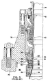
- tandemly-arranged lower primary, middle secondary and upper tertiary sealing assemblies 38,40,42 are provided in the positions illustrated in Figs. 2 and 3 about the pump shaft 34 and within the pump housing 30.
- the lower primary sealing assembly 38 which performs most of the pressure sealing is of the non-contacting hydrostatic type, whereas the middle secondary and upper tertiary sealing assemblies 40,42 are of the contacting or rubbing mechanical type.
- the lower hydrostatic primary sealing assembly 38 of the prior art pump 14 generally includes a lower annular runner 44 which is mounted to the pump shaft 34 for rotation therewith and an upper annular seal ring 46 which is stationarily mounted within the seal housing 32.
- the lower runner 44 includes an upper annular runner faceplate member 48 mounted by a hydrostatic clamp ring member 50 to a lower annular runner base or support member 52 which, in turn, is keyed to the pump shaft 34 by anti-rotation pins 54.
- the upper seal ring 46 includes a lower annular ring faceplate member 56 mounted by a hydrostatic clamp ring member 58 to an upper annular ring base or support member 60 which, in turn, is keyed to the seal housing 32 by anti-rotation pin 62 so as to prevent rotational movement of the upper seal ring 46 relative to the seal housing 32 but allow translatory movement of the upper seal ring 46 along pump shaft 34 toward and away from the lower runner 44.
- Facing (or top and bottom) surfaces 64,66 of the respective runner and ring upper and lower faceplate members 48,56 are biased toward one another as a result of the coolant pressure load on the pump shaft 34.
- the surfaces 64,66 normally do not frictionally engage one another, since the surface 66 of the lower seal ring faceplate member 56 is tapered at a shallow angle with respect to the substantially flat and horizontal surface 64 on the upper runner faceplate member 48.
- Such tapering provides a flowing film of coolant fluid between the surfaces 64,66 which, in turn, allows the lower runner 44 and upper seal ring 46 to rotate relative to one another in a "film-riding" mode.
- the primary sealing assembly 38 normally operates in a film-riding mode, some provision must be made for handling coolant fluid which "leaks off" in the annular space between the seal housing 32 and the shaft 34 rotatably mounted thereto and enters through injection supply port 68 as seen in Fig. 2. Accordingly, the seal housing 32 includes a primary leakoff port 70, whereas leakoff port 72 accommodates coolant fluid leakoff from the secondary sealing assembly 40 and leakoff port 74 accommodates coolant fluid leakoff from the tertiary sealing assembly 42.
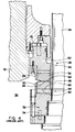
- FIG. 5 and 6 there is illustrated in greater detail the prior art lower base or support member 52 of the lower annular runner 44 of the lower hydrostatic primary sealing assembly 38 of Figs. 2-4.
- the lower support member 52 of the lower runner 44 is an annular body 76 having a central bore 78 receiving the pump shaft 34 therethrough.
- a generally planar top annular surface 80 is defined on the upper side of the body 76 for flush contact with a generally planar bottom annular surface 82 (Fig. 4) on the lower side of the upper runner faceplate member 48.
- An outer circumferential groove 84 and an inner circumferential pressure communication groove 86 being radially spaced from the outer groove 84 are defined in the top surface 80 of the body 76 nearer to an inner circumferential edge 88 than to an outer circumferential edge 90 of the top surface of the body.
- the grooves 84,86 are intersected by radial pressure communication grooves 92 which extend between the outer and inner edges 86,88 of the body 76.
- the outer groove 86 seats a separate sealing element in the form of an O-ring 93 for providing a seal between the top surface 80 of the lower support member 52 and bottom surface 82 of the upper faceplate member 48.
- the above-described prior art construction of the runner faceplate and support members 48,52 provides a large area of contact at the planar surfaces 80,82 thereof.
- the large area of surface contact permits a decreasing temperature gradient to progress axially from the support member 52 through the faceplate member 48 which can result in thermal distortion of the faceplate member that can cause the facing surfaces 64,66 of the primary sealing assembly 38 to contact and fail.
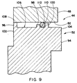
- Figs. 7-9 there is shown a modified construction of the annular body 94 of the runner support member 52 in accordance with the present invention which avoids the problems arising from the prior art construction described above.
- the modified construction is shown and described in relation to the runner support member 52 only, it should be understood that the modifications can also be applied, if desired, to the seal ring support member 60 of the primary sealing assembly 38.
- the modified construction can be applied to one of the respective faceplate members 48,56 instead of one of the support members 52,60.
- the annular body 94 of the lower support member 52 has spaced apart outer, middle and inner raised circumferential ribs 96,98,100 defined on an upper side thereof.
- the outer rib 96 is located at an outer circumferential edge 102 on the annular body 94, whereas the inner rib 100 is located near to an inner circumferential edge 104 on the body.
- An annular recessed cavity 106 is defined in the upper side of the body 94 between the outer and inner ribs 96,100.
- the outer rib 96 has a greater height than both the middle and inner ribs 98,100 such that the upper faceplate member 48 is engagably supported at its bottom surface 82 solely by the generally planar narrow top surface 108 of the outer rib 96 on the upper side of the body 94.
- the shorter inner rib 100 is provided for retaining the separate annular O-ring 110 between the respective adjacent sides of the faceplate and support members 48,52 during assembling of the primary sealing assembly 38.
- the O-ring 110 has a cross-sectional diameter greater than the height of the inner rib 100 so as to project from the upper side of the support member 52, beyond the inner rib 100 and beyond the outer rib 96, and toward the adjacent lower side of the faceplate member 48 for sealably engaging the faceplate member.
- the middle raised circumferential rib 98 defined on the annular support member body 94 between the outer and inner ribs 96,100, although not essential, is desirable to assist in holding the O-ring 110 in the desired position during assembling of the primary sealing assembly components and for constraint of the o-ring during possible reverse pressurization.
- the middle rib 98 is spaced much closer to the inner rib 100 than the outer rib 96 so as to define the circumferential groove 112 in which the annular O-ring 110 is seated.
- the inner rib 100 has a cross-sectional height greater than that of the middle rib 98 but less than that of the outer rib 96.
- the recessed cavity 106 so defined on the upper side of the support member body 94 between the outer and inner ribs 96,100 substantially spaces (except for the narrow contact at the top surface 108 of the outer rib 96) the upper faceplate member 48 from the lower support member 52 to thereby thermally insulate the faceplate member from the support member.
- a thermally insulative material such as water (not shown) can be contained in the recessed cavity 106.
- a suitable alternative insulative material can also be used.
- the outer rib 96 has at least one and preferably a pair of grooves 114 defined through it in order to provide communication between the housing interior 36 and the recessed cavity 106, permitting inflow of pressurized water into the cavity. The water forms a relatively stagnant non-circulating pool within the cavity 106.
- the provision of the recessed cavity 106 to increase the thermal stability of the sealing assembly 38 coincidentally provides manufacturing, inspection, and operational improvements as well.
- inspection of the flatness of the seating surfaces on both the faceplate and support members can be carried out with greater validity since the inspection effort can now be concentrated on the remaining 5%.
- decreasing the contact area by 95% decreases the time required in lapping the contact surfaces and reduces the concern with thermal distortion during performance of the surface lapping.
- the reduction of the effective contact surfaces by 95% significantly reduces the probability of dirt locating therebetween, of accidentally damaging the surfaces, of erratic seal performance due to occurrence of intermolecular attraction, and of deleterious effects from gas trapped between contacting surfaces.
Landscapes
- Engineering & Computer Science (AREA)
- General Engineering & Computer Science (AREA)
- Mechanical Engineering (AREA)
- Physics & Mathematics (AREA)
- Plasma & Fusion (AREA)
- High Energy & Nuclear Physics (AREA)
- Structures Of Non-Positive Displacement Pumps (AREA)
Claims (5)
- Hydrostatische Wellendichtungsanordnung, die folgendes umfasst: ein Paar Dichtungsteile (44,46), die einander gegenüber angeordnet sind, um relative Drehung durchzumachen; wobei eins der Dichtungsteile (44) ein ringförmiges Tragglied (52) einschliesst und eine ringförmige Flächenplatte (48), die auf dem Tragglied (52) angebracht ist, eines der Trag- und Flächenplattenglieder (52,48) eine darauf neben dem anderen der Glieder angeordnete Dichtungsfläche hat; die andere einen ringförmigen Körper (94) mit radial beabstandeten äußeren und inneren peripheren Rändern (102,104) umfasst, gekennzeichnet durch eine periphere äußere Rippe (96), die axial von dem ringförmigen Körper (94) auf eine vorbestimmte ersten Höhe hervorragt, eine innere periphere Rippe (100), die axial von dem ringförmigen Körper (94) neben dessen inneren peripheren Randes auf eine vobestimte zweite Höhe hervorragt, die geringer als die erste Höhe ist, und einen flexiblen dichtenden O-Ring (110), der vor dem ringförmigen Körper (94) getrennt ist und darauf um die innere periphere Rippe (100) angeordnet ist, und einen Querschnittsdurchmesser hat, der größer als die erste Höhe ist, wobei die erste Höhe ausreichend groß ist, um einen ringförmigen Hohlraum (106) zwischen der äußeren Rippe (96) und dem O-Ring (110) auf der Fläche des ringförmigen Körpers (94) zu bilden, was einen Raum zwischen der Flächenplatte und den Traggliedern liefert, der mit Flüssigkeit gefüllt werden kann, wobei das eine Glied (52), wenn es auf der peripheren äußeren Rippe (96) liegt, den O-Ring (110) zusammendrückt und dichtend in ihn eingreift.
- Wellendichtungsanordnung nach Anspruch 1, dadurch gekennzeichnet, daß der eine Dichtungsteil (44) eine mittlere periphere Rippe (98) einschliesst, die zwischen den äußeren und inneren Rippen (96,100) neben der inneren Rippe (100) angeordnet ist, um mit der inneren Rippe (100) eine Nut (112) zu definieren, um den O-Ring (110) zu empfangen.
- Wellendichtungsanordnung nach Anspruch 2, dadurch gekennzeichnet, daß die mittlere Rippe (98) eine axiale Höhe hat, die geringer als die der inneren Rippe (100) ist.
- Wellendichtungsanordnung nach einem der Ansprüche 1, 2 oder 3, dadurch gekennzeichnet, daß ein thermisches Isoliermaterial in dem Hohlraum (106) enthalten ist.
- Wellendichtungsanordnung nach einem der Ansprüche 1 bis 4, dadurch gekennzeichnet, daß die äußere Rippe (96) wenigstens eine sich dadurch erstreckende Nut (114) hat, um Verbindung zwischen dem Äußeren der äußeren Rippe (96) und dem Hohlraum (106) zu liefern.
Applications Claiming Priority (2)
| Application Number | Priority Date | Filing Date | Title |
|---|---|---|---|
| US466143 | 1990-01-16 | ||
| US07/466,143 US5024452A (en) | 1990-01-16 | 1990-01-16 | Reactor coolant pump having thermally stabilized hydrostatic sealing assembly |
Publications (2)
| Publication Number | Publication Date |
|---|---|
| EP0437973A1 EP0437973A1 (de) | 1991-07-24 |
| EP0437973B1 true EP0437973B1 (de) | 1995-03-08 |
Family
ID=23850663
Family Applications (1)
| Application Number | Title | Priority Date | Filing Date |
|---|---|---|---|
| EP90314214A Expired - Lifetime EP0437973B1 (de) | 1990-01-16 | 1990-12-21 | Kühlmittelpumpe für einen Reaktor mit hitzebeständiger hydrostatischer Dichtungsanordnung |
Country Status (6)
| Country | Link |
|---|---|
| US (1) | US5024452A (de) |
| EP (1) | EP0437973B1 (de) |
| JP (1) | JP2879980B2 (de) |
| KR (1) | KR100232326B1 (de) |
| DE (1) | DE69017644T2 (de) |
| ES (1) | ES2071052T3 (de) |
Cited By (1)
| Publication number | Priority date | Publication date | Assignee | Title |
|---|---|---|---|---|
| CN104251226A (zh) * | 2014-09-12 | 2014-12-31 | 乐山东方动力节能设备有限公司 | 新型冷却塔水力风机用组合式主轴密封 |
Families Citing this family (6)
| Publication number | Priority date | Publication date | Assignee | Title |
|---|---|---|---|---|
| US7287756B2 (en) * | 2004-03-08 | 2007-10-30 | Westinghouse Electric Co Llc | Film riding shaft seal |
| KR100694970B1 (ko) * | 2006-12-06 | 2007-03-14 | 노진구 | 숯과 송진이 내재 된 미드솔을 갖는 신발 |
| KR101409879B1 (ko) * | 2011-12-29 | 2014-06-20 | 두산중공업 주식회사 | 원자로 냉각재 펌프 |
| CN102606537A (zh) * | 2012-03-27 | 2012-07-25 | 上海阿波罗机械股份有限公司 | 一种安全壳喷淋泵 |
| GB2528836B (en) * | 2014-06-26 | 2017-12-27 | Aes Eng Ltd | Mechanical seal control mechanism |
| US10145377B2 (en) * | 2015-04-02 | 2018-12-04 | Curtiss-Wright Electro-Mechanical Corporation | Canned motor pump thrust shoe heat shield |
Family Cites Families (21)
| Publication number | Priority date | Publication date | Assignee | Title |
|---|---|---|---|---|
| US3717353A (en) * | 1969-07-18 | 1973-02-20 | Champlain Power Prod Ltd | Stator ring for face-type fluid seals |
| US3751045A (en) * | 1970-03-19 | 1973-08-07 | Ingersoll Rand Co | Fluid seal |
| SE347334B (de) * | 1970-12-30 | 1972-07-31 | Stenberg Flygt Ab | |
| US3973780A (en) * | 1974-12-23 | 1976-08-10 | Ingersoll-Rand Company | Seal mounting arrangement |
| GB1499291A (en) * | 1975-01-10 | 1978-01-25 | Westinghouse Electric Corp | Nuclear reactor apparatus |
| US4069100A (en) * | 1975-02-13 | 1978-01-17 | Westinghouse Electric Corporation | Adsorption seal for nuclear reactors |
| SE411941B (sv) * | 1977-02-17 | 1980-02-11 | Sandvik Ab | Tetningselement |
| US4341732A (en) * | 1979-05-29 | 1982-07-27 | Westinghouse Electric Corp. | Nuclear reactor dip seal |
| US4275891A (en) * | 1979-08-14 | 1981-06-30 | Westinghouse Electric Corp. | Face type shaft seal for liquid metal pumps |
| JPS5642794A (en) * | 1979-09-17 | 1981-04-21 | Hitachi Ltd | Cover for diesel generator |
| US4511149A (en) * | 1983-09-29 | 1985-04-16 | Borg-Warner Corporation | Mechanical seal with cylindrical balance sleeve |
| US4557489A (en) * | 1984-03-23 | 1985-12-10 | Borg-Warner Corporation | Pressure balanced seal |
| FI70077C (fi) * | 1984-11-06 | 1986-09-12 | Safematic Ltd Oy | Glidringstaetning |
| US4693481A (en) * | 1985-05-31 | 1987-09-15 | Westinghouse Electric Corp. | Film-riding shaft seal formed from high-purity silicon nitride |
| JPS6223503A (ja) * | 1985-07-22 | 1987-01-31 | Mitsubishi Heavy Ind Ltd | タ−ボ機械の軸シ−ル装置 |
| JPS6229495U (de) * | 1985-08-07 | 1987-02-23 | ||
| FI74121C (fi) * | 1986-01-22 | 1988-08-01 | Safematic Ltd Oy | Glidringstaetning. |
| SU1341427A1 (ru) * | 1986-05-19 | 1987-09-30 | М.В.Коротов | Торцовое уплотнение |
| US4792146A (en) * | 1987-02-17 | 1988-12-20 | University Of New Mexico | Radially compliant - zero net thermal radial taper mechanical face seal |
| ES2025232B3 (es) * | 1987-04-08 | 1992-03-16 | Westinghouse Electric Corp | Bomba a reaccion de enfriamiento de superficies con cobertura de nitrato de titanio |
| JPS6447962U (de) * | 1987-09-21 | 1989-03-24 |
-
1990
- 1990-01-16 US US07/466,143 patent/US5024452A/en not_active Expired - Lifetime
- 1990-12-21 DE DE69017644T patent/DE69017644T2/de not_active Expired - Fee Related
- 1990-12-21 ES ES90314214T patent/ES2071052T3/es not_active Expired - Lifetime
- 1990-12-21 EP EP90314214A patent/EP0437973B1/de not_active Expired - Lifetime
-
1991
- 1991-01-10 JP JP3001516A patent/JP2879980B2/ja not_active Expired - Lifetime
- 1991-01-15 KR KR1019910000521A patent/KR100232326B1/ko not_active Expired - Lifetime
Cited By (1)
| Publication number | Priority date | Publication date | Assignee | Title |
|---|---|---|---|---|
| CN104251226A (zh) * | 2014-09-12 | 2014-12-31 | 乐山东方动力节能设备有限公司 | 新型冷却塔水力风机用组合式主轴密封 |
Also Published As
| Publication number | Publication date |
|---|---|
| DE69017644T2 (de) | 1995-09-28 |
| EP0437973A1 (de) | 1991-07-24 |
| ES2071052T3 (es) | 1995-06-16 |
| KR910014959A (ko) | 1991-08-31 |
| JPH04214998A (ja) | 1992-08-05 |
| KR100232326B1 (ko) | 1999-12-01 |
| JP2879980B2 (ja) | 1999-04-05 |
| US5024452A (en) | 1991-06-18 |
| DE69017644D1 (de) | 1995-04-13 |
Similar Documents
| Publication | Publication Date | Title |
|---|---|---|
| EP0435485B1 (de) | Entlüftungseinrichtung für die Dichtung einer Reaktorkühlmittelpumpe | |
| US5171024A (en) | Reactor coolant pump shaft seal utilizing shape memory metal | |
| US9217441B2 (en) | Pump seal with thermal retracting actuator | |
| EP0439308B1 (de) | Reaktorkühlmittelpumpe mit verbesserten sekundärdichtungseinheiten | |
| EP0305945B1 (de) | Hydrostatische Dichtungseinrichtung für Reaktorkühlpumpe mit von aussen unter Druck gesetzter hydraulischer Ausgleichsammer | |
| US9206791B2 (en) | Pump seal with thermal retracting actuator | |
| EP3545219B1 (de) | Hydrostatische mechanische gleitringdichtung | |
| US4961678A (en) | Reactor coolant pump having double dam seal with self-contained injection pump mechanism | |
| EP0437973B1 (de) | Kühlmittelpumpe für einen Reaktor mit hitzebeständiger hydrostatischer Dichtungsanordnung | |
| EP0295473B1 (de) | Kühlmittelpumpe für einen Reaktor mit hydrostatischer Dichtungsanordnung mit hydraulischem Gleichgewicht | |
| EP0203317B1 (de) | Wellendichtung | |
| US4847041A (en) | Reactor coolant pump auxiliary seal for reactor coolant system vacuum degasification | |
| CA3159703A1 (en) | Contacting seal arrangement for low and high pressure applications | |
| US4976446A (en) | Reactor coolant pump auxiliary seal for reactor coolant system vacuum degasification | |
| JPS61182488A (ja) | インタ−ナルポンプ |
Legal Events
| Date | Code | Title | Description |
|---|---|---|---|
| PUAI | Public reference made under article 153(3) epc to a published international application that has entered the european phase |
Free format text: ORIGINAL CODE: 0009012 |
|
| AK | Designated contracting states |
Kind code of ref document: A1 Designated state(s): BE DE ES FR GB IT |
|
| 17P | Request for examination filed |
Effective date: 19920117 |
|
| 17Q | First examination report despatched |
Effective date: 19930702 |
|
| GRAA | (expected) grant |
Free format text: ORIGINAL CODE: 0009210 |
|
| AK | Designated contracting states |
Kind code of ref document: B1 Designated state(s): BE DE ES FR GB IT |
|
| REF | Corresponds to: |
Ref document number: 69017644 Country of ref document: DE Date of ref document: 19950413 |
|
| ET | Fr: translation filed | ||
| ITF | It: translation for a ep patent filed | ||
| REG | Reference to a national code |
Ref country code: ES Ref legal event code: FG2A Ref document number: 2071052 Country of ref document: ES Kind code of ref document: T3 |
|
| PLBE | No opposition filed within time limit |
Free format text: ORIGINAL CODE: 0009261 |
|
| STAA | Information on the status of an ep patent application or granted ep patent |
Free format text: STATUS: NO OPPOSITION FILED WITHIN TIME LIMIT |
|
| 26N | No opposition filed | ||
| PGFP | Annual fee paid to national office [announced via postgrant information from national office to epo] |
Ref country code: DE Payment date: 20011228 Year of fee payment: 12 |
|
| REG | Reference to a national code |
Ref country code: GB Ref legal event code: IF02 |
|
| PG25 | Lapsed in a contracting state [announced via postgrant information from national office to epo] |
Ref country code: DE Free format text: LAPSE BECAUSE OF NON-PAYMENT OF DUE FEES Effective date: 20030701 |
|
| PGFP | Annual fee paid to national office [announced via postgrant information from national office to epo] |
Ref country code: ES Payment date: 20071219 Year of fee payment: 18 |
|
| PGFP | Annual fee paid to national office [announced via postgrant information from national office to epo] |
Ref country code: IT Payment date: 20071215 Year of fee payment: 18 |
|
| PGFP | Annual fee paid to national office [announced via postgrant information from national office to epo] |
Ref country code: BE Payment date: 20071221 Year of fee payment: 18 |
|
| PGFP | Annual fee paid to national office [announced via postgrant information from national office to epo] |
Ref country code: GB Payment date: 20071106 Year of fee payment: 18 |
|
| PGFP | Annual fee paid to national office [announced via postgrant information from national office to epo] |
Ref country code: FR Payment date: 20071204 Year of fee payment: 18 |
|
| BERE | Be: lapsed |
Owner name: *WESTINHOUSE ELECTRIC CY LLC Effective date: 20081231 |
|
| GBPC | Gb: european patent ceased through non-payment of renewal fee |
Effective date: 20081221 |
|
| PG25 | Lapsed in a contracting state [announced via postgrant information from national office to epo] |
Ref country code: BE Free format text: LAPSE BECAUSE OF NON-PAYMENT OF DUE FEES Effective date: 20081231 |
|
| REG | Reference to a national code |
Ref country code: FR Ref legal event code: ST Effective date: 20090831 |
|
| PG25 | Lapsed in a contracting state [announced via postgrant information from national office to epo] |
Ref country code: GB Free format text: LAPSE BECAUSE OF NON-PAYMENT OF DUE FEES Effective date: 20081221 |
|
| REG | Reference to a national code |
Ref country code: ES Ref legal event code: FD2A Effective date: 20081222 |
|
| PG25 | Lapsed in a contracting state [announced via postgrant information from national office to epo] |
Ref country code: FR Free format text: LAPSE BECAUSE OF NON-PAYMENT OF DUE FEES Effective date: 20081231 Ref country code: ES Free format text: LAPSE BECAUSE OF NON-PAYMENT OF DUE FEES Effective date: 20081222 |
|
| PG25 | Lapsed in a contracting state [announced via postgrant information from national office to epo] |
Ref country code: IT Free format text: LAPSE BECAUSE OF NON-PAYMENT OF DUE FEES Effective date: 20081221 |