EP0437908A1 - Electronic capacitive ballast for fluorescent and other discharge lamps - Google Patents
Electronic capacitive ballast for fluorescent and other discharge lamps Download PDFInfo
- Publication number
- EP0437908A1 EP0437908A1 EP90300504A EP90300504A EP0437908A1 EP 0437908 A1 EP0437908 A1 EP 0437908A1 EP 90300504 A EP90300504 A EP 90300504A EP 90300504 A EP90300504 A EP 90300504A EP 0437908 A1 EP0437908 A1 EP 0437908A1
- Authority
- EP
- European Patent Office
- Prior art keywords
- lamp
- capacitor
- fluorescent
- starting
- ballast
- Prior art date
- Legal status (The legal status is an assumption and is not a legal conclusion. Google has not performed a legal analysis and makes no representation as to the accuracy of the status listed.)
- Withdrawn
Links
Images
Classifications
-
- H—ELECTRICITY
- H05—ELECTRIC TECHNIQUES NOT OTHERWISE PROVIDED FOR
- H05B—ELECTRIC HEATING; ELECTRIC LIGHT SOURCES NOT OTHERWISE PROVIDED FOR; CIRCUIT ARRANGEMENTS FOR ELECTRIC LIGHT SOURCES, IN GENERAL
- H05B41/00—Circuit arrangements or apparatus for igniting or operating discharge lamps
- H05B41/02—Details
- H05B41/04—Starting switches
- H05B41/042—Starting switches using semiconductor devices
- H05B41/044—Starting switches using semiconductor devices for lamp provided with pre-heating electrodes
- H05B41/046—Starting switches using semiconductor devices for lamp provided with pre-heating electrodes using controlled semiconductor devices
-
- H—ELECTRICITY
- H05—ELECTRIC TECHNIQUES NOT OTHERWISE PROVIDED FOR
- H05B—ELECTRIC HEATING; ELECTRIC LIGHT SOURCES NOT OTHERWISE PROVIDED FOR; CIRCUIT ARRANGEMENTS FOR ELECTRIC LIGHT SOURCES, IN GENERAL
- H05B41/00—Circuit arrangements or apparatus for igniting or operating discharge lamps
- H05B41/14—Circuit arrangements
- H05B41/16—Circuit arrangements in which the lamp is fed by DC or by low-frequency AC, e.g. by 50 cycles/sec AC, or with network frequencies
- H05B41/18—Circuit arrangements in which the lamp is fed by DC or by low-frequency AC, e.g. by 50 cycles/sec AC, or with network frequencies having a starting switch
Definitions
- the present invention relates to an electronic capacitive ballast for fluorescent and other discharge lamps which is particularly effective for starting purposes.
- fluorescent or other discharge lamps are started by an inductance coil being connected in series with a fluorescent lamp to the power source and a starter is connected across the fluorescent lamp with the starter contacts being initially closed.
- An object of the present invention is to provide an electronic capacitor ballast for fluorescent or other discharge lamps which overcomes at least some of the disadvantages of the prior art systems.
- an electronic capacitive ballast for fluorescent or other discharge lamps comprising at least one capacitor having a value of up to 20 ⁇ F, said capacitor being connected to a power source and at least one inductance coil of up to 5 H (Henry), said inductance coil being connected to an input terminal of a starting device for undirectional passage of current during starting of the fluorescent lamp, said starting device comprising a triac, silicon controlled rectifier or the like, a diode and at least one preset resistor, said starting device having output terminals each connecting the fluorescent lamp or other discharge lamp and with a further terminal connectable to said power source.
- the electronic capacitive ballast for fluorescent and other discharge lamps according to the invention may overcome some or all of the above disadvantages and may provide a current limiting feature, improve the system power factor to a leading power factor, avoid the use of traditional starters, facilitate single pin lighting to achieve the best results at a cheaper cost and may ensure minimal power loss by the components used.
- some advantages obtained by preferred embodiments of the invention are as follows:
- the said capacitors are connected in series-parallel combination.
- the said inductance coils may be connected in series-parallel combination.
- the values of the capacitor may range from 4 ⁇ . F.D. to 20 ⁇ . F.D. and that of the inductance coil may range from 30 mNH (Multi-Henry) to 2H.
- the invention provides a starter circuit for a fluorescent or other discharge lamp, comprising at least one capacitor and inductance coil for connection in series between an a.c. power source and a lamp, and a starting device comprising a triac, silicon controlled rectifier or like means for the undirectional passage of current during starting of the lamp, the device being arranged so that during starting the capacitor is charged during one half cycle of the a.c. whilst during the other half cycle the capacitor provides a stored voltage which is added to the source voltage applied to the lamp, the starting device being adapted not to allow the passage of current during operation of the lamp after starting.
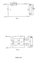
- the inductance coil (1) is connected in series with a fluorescent lamp (3) to the power source (P,N).
- a starter (2) is connected across the fluorescent lamp (3). The starter (2) contacts are initially closed.
- the starter On application of voltage from the power source a current determined by the impedence of the inductance coil flows there through and as a consequence the filaments of the lamp become heated.
- the starter because of its basic design opens the circuit after a certain interval of time which causes an inductive voltage kick across the ends of the discharge lamp. Due to the thermionic and field emissions the fluorescent lamp discharges, the lamp is lit up. Since the voltage across the ends of the fluorescent lamp is about 100 volts which is quite insufficient to cause the starter to close, the lamp remains lit. The inductance limits the current through the fluorescent lamps.
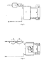
- Figure 2 illustrates another conventional circuit diagram using a high frequency electronic choke.
- the system operates as follows:
- an A.C. to D.C. converter (5) comprising of diodes, filter circuit etc. converts the A.C. to D.C.
- the D.C. supply is now chopped in a chopper (6) which consists of triacs or SCR'S, transistors, resistors, capacitors etc.
- the high frequency chopped D.C. 10 to 20 K Hz is stabilised through a small inductance coil (not shown in figure) and is available at two pairs of terminals 7 and 8 which are connected to the two ends of the lamp. A typical voltage available at these terminal pairs is 75 volts.
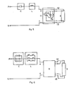
- Terminals (P,N) are connected to an A.C. power source.
- Terminal (a) of the capacitor (9) is connected to terminal (P) of a Power source whereas the terminal (b) of the capacitor (9) is connected to terminal (c) of an inductance (10), the other terminal (d) of the inductance (10) is connected to the input terminal (e) of the starting device (11).
- the terminal (f) of the starting device (10) is connected to the other terminal (N) of the power source.
- the two pins or terminals (12) of the starting device are connected to the fluorescent lamp (3).
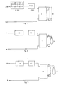
- the circuit diagram of the operation is shown in Figure 4.
- C is a single capacitor or a bank of capacitors.
- L is a small stabilising inductance coil or a plurality of inductance coils.
- T is a triac
- D is a diode and R-1, R-2 are presets.
- R-2 fires the triac to provide the charging current through the capacitor.
- the capacitor C will get charged to the peak voltage of the AC wave namely 2 xVRMS (Voltage Root Mean Square).
- the circuit also causes the filaments of the fluorescent lamp to get heated.
- the triac is not fired.
- the negative peak voltage plus capacitor voltage is available across the fluorescent lamp. This is ample to cause conduction in the fluorescent lamp. If during the first cycle the fluorescent lamp is not lit up, the circuit causes the current to flow through, thus heating the fluorescent lamp further. The process is repeated in the subsequent cycles, finally lighting the lamp.
- the voltage across the lit fluorescent lamp is 80 to 100 volts. As the presets R-1 and R-2 are adjusted to fire the triac at/near the peak of the AC cycle the voltage of 80 to 100 available will not be sufficient to fire the triac while the lamp is lit.
- the current limiting is done by capacitor C.
- the small inductance (L) acts to stabilise the current.
- the capacitive ballast has many advantages.
- Figures 5 to 9 illustrate alternative embodiments whose components differ from those of the figure 3 and 4 embodiment only as specified in the brief figure description above, and which all operate in a manner similar to the embodiment described in detail.
Landscapes
- Circuit Arrangements For Discharge Lamps (AREA)
Applications Claiming Priority (1)
| Application Number | Priority Date | Filing Date | Title |
|---|---|---|---|
| IN797DE1989 IN176607B (enExample) | 1989-09-07 | 1989-09-07 |
Publications (1)
| Publication Number | Publication Date |
|---|---|
| EP0437908A1 true EP0437908A1 (en) | 1991-07-24 |
Family
ID=11091283
Family Applications (1)
| Application Number | Title | Priority Date | Filing Date |
|---|---|---|---|
| EP90300504A Withdrawn EP0437908A1 (en) | 1989-09-07 | 1990-01-18 | Electronic capacitive ballast for fluorescent and other discharge lamps |
Country Status (3)
| Country | Link |
|---|---|
| EP (1) | EP0437908A1 (enExample) |
| AU (1) | AU4790190A (enExample) |
| IN (1) | IN176607B (enExample) |
Citations (5)
| Publication number | Priority date | Publication date | Assignee | Title |
|---|---|---|---|---|
| US3978368A (en) * | 1973-02-21 | 1976-08-31 | Hitachi, Ltd. | Discharge lamp control circuit |
| US4015167A (en) * | 1974-07-02 | 1977-03-29 | The General Electric Company Limited | Circuits for operating electric discharge lamps |
| FR2441990A1 (fr) * | 1978-11-17 | 1980-06-13 | Lampes Sa | Dispositif d'allumage electronique pour lampe fluorescente, et systeme d'eclairage equipe d'un tel dispositif |
| FR2546357A1 (fr) * | 1983-05-20 | 1984-11-23 | Gloria Sa | Dispositif de demarrage et d'alimentation d'un tube a decharge dans un gaz |
| EP0327404A1 (en) * | 1988-02-04 | 1989-08-09 | Century International Ltd. | Electronic ballast and starter circuit |
-
1989
- 1989-09-07 IN IN797DE1989 patent/IN176607B/en unknown
-
1990
- 1990-01-11 AU AU47901/90A patent/AU4790190A/en not_active Abandoned
- 1990-01-18 EP EP90300504A patent/EP0437908A1/en not_active Withdrawn
Patent Citations (5)
| Publication number | Priority date | Publication date | Assignee | Title |
|---|---|---|---|---|
| US3978368A (en) * | 1973-02-21 | 1976-08-31 | Hitachi, Ltd. | Discharge lamp control circuit |
| US4015167A (en) * | 1974-07-02 | 1977-03-29 | The General Electric Company Limited | Circuits for operating electric discharge lamps |
| FR2441990A1 (fr) * | 1978-11-17 | 1980-06-13 | Lampes Sa | Dispositif d'allumage electronique pour lampe fluorescente, et systeme d'eclairage equipe d'un tel dispositif |
| FR2546357A1 (fr) * | 1983-05-20 | 1984-11-23 | Gloria Sa | Dispositif de demarrage et d'alimentation d'un tube a decharge dans un gaz |
| EP0327404A1 (en) * | 1988-02-04 | 1989-08-09 | Century International Ltd. | Electronic ballast and starter circuit |
Also Published As
| Publication number | Publication date |
|---|---|
| IN176607B (enExample) | 1996-08-03 |
| AU4790190A (en) | 1991-03-14 |
Similar Documents
| Publication | Publication Date | Title |
|---|---|---|
| US5612597A (en) | Oscillating driver circuit with power factor correction, electronic lamp ballast employing same and driver method | |
| US5223767A (en) | Low harmonic compact fluorescent lamp ballast | |
| JP2613874B2 (ja) | Dc−acコンバータ | |
| US6072282A (en) | Frequency controlled quick and soft start gas discharge lamp ballast and method therefor | |
| US5049789A (en) | Electronic capacitive ballast for fluorescent and other discharge lamps | |
| JP2001523389A (ja) | トライアック可調光バラスト | |
| US6700331B2 (en) | Control circuit for dimming fluorescent lamps | |
| JPH10501651A (ja) | 放電ランプ安定器 | |
| WO2000022892A2 (en) | Ballast power control circuit | |
| JPS5874000A (ja) | ガス放電ランプ照明装置の照度を制御するための方法および装置 | |
| KR20000016490A (ko) | 저전력 인자를 갖는 트라이액 조광 가능 소형 형광 램프 | |
| EP0150536B1 (en) | Ballast adaptor for improving operation of fluorescent lamps | |
| JP2000511692A (ja) | 電流保護を備えるコンパクト蛍光ランプのためのバラスト | |
| US5543690A (en) | High voltage ignition circuit for a discharge lamp | |
| US4006384A (en) | Lead-lag, series-sequence starting and operating apparatus for three to six fluorescent lamps | |
| EP0224980A1 (en) | Device and process for lighting a fluorescent discharge lamp | |
| EP0581912B1 (en) | Improved low loss ballast system | |
| JPH10513010A (ja) | 冷陰極放電ランプの点灯方法及び回路装置 | |
| US6674249B1 (en) | Resistively ballasted gaseous discharge lamp circuit and method | |
| US4818918A (en) | High frequency lighting system for gas discharge lamps | |
| EP0437908A1 (en) | Electronic capacitive ballast for fluorescent and other discharge lamps | |
| JPH06217550A (ja) | 高力率電源回路 | |
| KR100291689B1 (ko) | 방전램프용 저 손실의 전자식 안정저항 회로 | |
| CN1180663C (zh) | 荧光灯电子镇流器电路 | |
| HU197139B (en) | Ballast of constant input and lamp power for discharge lamps of high lamp power |
Legal Events
| Date | Code | Title | Description |
|---|---|---|---|
| PUAI | Public reference made under article 153(3) epc to a published international application that has entered the european phase |
Free format text: ORIGINAL CODE: 0009012 |
|
| AK | Designated contracting states |
Kind code of ref document: A1 Designated state(s): DE FR GB |
|
| 17P | Request for examination filed |
Effective date: 19910816 |
|
| STAA | Information on the status of an ep patent application or granted ep patent |
Free format text: STATUS: THE APPLICATION HAS BEEN WITHDRAWN |
|
| 18W | Application withdrawn |
Withdrawal date: 19921228 |
|
| R18W | Application withdrawn (corrected) |
Effective date: 19921228 |