EP0437908A1 - Electronic capacitive ballast for fluorescent and other discharge lamps - Google Patents
Electronic capacitive ballast for fluorescent and other discharge lamps Download PDFInfo
- Publication number
- EP0437908A1 EP0437908A1 EP90300504A EP90300504A EP0437908A1 EP 0437908 A1 EP0437908 A1 EP 0437908A1 EP 90300504 A EP90300504 A EP 90300504A EP 90300504 A EP90300504 A EP 90300504A EP 0437908 A1 EP0437908 A1 EP 0437908A1
- Authority
- EP
- European Patent Office
- Prior art keywords
- lamp
- capacitor
- fluorescent
- starting
- ballast
- Prior art date
- Legal status (The legal status is an assumption and is not a legal conclusion. Google has not performed a legal analysis and makes no representation as to the accuracy of the status listed.)
- Withdrawn
Links
Images
Classifications
-
- H—ELECTRICITY
- H05—ELECTRIC TECHNIQUES NOT OTHERWISE PROVIDED FOR
- H05B—ELECTRIC HEATING; ELECTRIC LIGHT SOURCES NOT OTHERWISE PROVIDED FOR; CIRCUIT ARRANGEMENTS FOR ELECTRIC LIGHT SOURCES, IN GENERAL
- H05B41/00—Circuit arrangements or apparatus for igniting or operating discharge lamps
- H05B41/02—Details
- H05B41/04—Starting switches
- H05B41/042—Starting switches using semiconductor devices
- H05B41/044—Starting switches using semiconductor devices for lamp provided with pre-heating electrodes
- H05B41/046—Starting switches using semiconductor devices for lamp provided with pre-heating electrodes using controlled semiconductor devices
-
- H—ELECTRICITY
- H05—ELECTRIC TECHNIQUES NOT OTHERWISE PROVIDED FOR
- H05B—ELECTRIC HEATING; ELECTRIC LIGHT SOURCES NOT OTHERWISE PROVIDED FOR; CIRCUIT ARRANGEMENTS FOR ELECTRIC LIGHT SOURCES, IN GENERAL
- H05B41/00—Circuit arrangements or apparatus for igniting or operating discharge lamps
- H05B41/14—Circuit arrangements
- H05B41/16—Circuit arrangements in which the lamp is fed by dc or by low-frequency ac, e.g. by 50 cycles/sec ac, or with network frequencies
- H05B41/18—Circuit arrangements in which the lamp is fed by dc or by low-frequency ac, e.g. by 50 cycles/sec ac, or with network frequencies having a starting switch
Definitions
- the present invention relates to an electronic capacitive ballast for fluorescent and other discharge lamps which is particularly effective for starting purposes.
- fluorescent or other discharge lamps are started by an inductance coil being connected in series with a fluorescent lamp to the power source and a starter is connected across the fluorescent lamp with the starter contacts being initially closed.
- An object of the present invention is to provide an electronic capacitor ballast for fluorescent or other discharge lamps which overcomes at least some of the disadvantages of the prior art systems.
- an electronic capacitive ballast for fluorescent or other discharge lamps comprising at least one capacitor having a value of up to 20 ⁇ F, said capacitor being connected to a power source and at least one inductance coil of up to 5 H (Henry), said inductance coil being connected to an input terminal of a starting device for undirectional passage of current during starting of the fluorescent lamp, said starting device comprising a triac, silicon controlled rectifier or the like, a diode and at least one preset resistor, said starting device having output terminals each connecting the fluorescent lamp or other discharge lamp and with a further terminal connectable to said power source.
- the electronic capacitive ballast for fluorescent and other discharge lamps according to the invention may overcome some or all of the above disadvantages and may provide a current limiting feature, improve the system power factor to a leading power factor, avoid the use of traditional starters, facilitate single pin lighting to achieve the best results at a cheaper cost and may ensure minimal power loss by the components used.
- some advantages obtained by preferred embodiments of the invention are as follows:
- the said capacitors are connected in series-parallel combination.
- the said inductance coils may be connected in series-parallel combination.
- the values of the capacitor may range from 4 ⁇ . F.D. to 20 ⁇ . F.D. and that of the inductance coil may range from 30 mNH (Multi-Henry) to 2H.
- the invention provides a starter circuit for a fluorescent or other discharge lamp, comprising at least one capacitor and inductance coil for connection in series between an a.c. power source and a lamp, and a starting device comprising a triac, silicon controlled rectifier or like means for the undirectional passage of current during starting of the lamp, the device being arranged so that during starting the capacitor is charged during one half cycle of the a.c. whilst during the other half cycle the capacitor provides a stored voltage which is added to the source voltage applied to the lamp, the starting device being adapted not to allow the passage of current during operation of the lamp after starting.
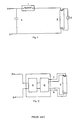
- the inductance coil (1) is connected in series with a fluorescent lamp (3) to the power source (P,N).
- a starter (2) is connected across the fluorescent lamp (3). The starter (2) contacts are initially closed.
- the starter On application of voltage from the power source a current determined by the impedence of the inductance coil flows there through and as a consequence the filaments of the lamp become heated.
- the starter because of its basic design opens the circuit after a certain interval of time which causes an inductive voltage kick across the ends of the discharge lamp. Due to the thermionic and field emissions the fluorescent lamp discharges, the lamp is lit up. Since the voltage across the ends of the fluorescent lamp is about 100 volts which is quite insufficient to cause the starter to close, the lamp remains lit. The inductance limits the current through the fluorescent lamps.
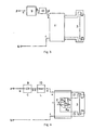
- Figure 2 illustrates another conventional circuit diagram using a high frequency electronic choke.
- the system operates as follows:
- an A.C. to D.C. converter (5) comprising of diodes, filter circuit etc. converts the A.C. to D.C.
- the D.C. supply is now chopped in a chopper (6) which consists of triacs or SCR'S, transistors, resistors, capacitors etc.
- the high frequency chopped D.C. 10 to 20 K Hz is stabilised through a small inductance coil (not shown in figure) and is available at two pairs of terminals 7 and 8 which are connected to the two ends of the lamp. A typical voltage available at these terminal pairs is 75 volts.
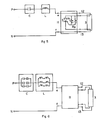
- Terminals (P,N) are connected to an A.C. power source.
- Terminal (a) of the capacitor (9) is connected to terminal (P) of a Power source whereas the terminal (b) of the capacitor (9) is connected to terminal (c) of an inductance (10), the other terminal (d) of the inductance (10) is connected to the input terminal (e) of the starting device (11).
- the terminal (f) of the starting device (10) is connected to the other terminal (N) of the power source.
- the two pins or terminals (12) of the starting device are connected to the fluorescent lamp (3).
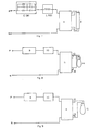
- the circuit diagram of the operation is shown in Figure 4.
- C is a single capacitor or a bank of capacitors.
- L is a small stabilising inductance coil or a plurality of inductance coils.
- T is a triac
- D is a diode and R-1, R-2 are presets.
- R-2 fires the triac to provide the charging current through the capacitor.
- the capacitor C will get charged to the peak voltage of the AC wave namely 2 xVRMS (Voltage Root Mean Square).
- the circuit also causes the filaments of the fluorescent lamp to get heated.
- the triac is not fired.
- the negative peak voltage plus capacitor voltage is available across the fluorescent lamp. This is ample to cause conduction in the fluorescent lamp. If during the first cycle the fluorescent lamp is not lit up, the circuit causes the current to flow through, thus heating the fluorescent lamp further. The process is repeated in the subsequent cycles, finally lighting the lamp.
- the voltage across the lit fluorescent lamp is 80 to 100 volts. As the presets R-1 and R-2 are adjusted to fire the triac at/near the peak of the AC cycle the voltage of 80 to 100 available will not be sufficient to fire the triac while the lamp is lit.
- the current limiting is done by capacitor C.
- the small inductance (L) acts to stabilise the current.
- the capacitive ballast has many advantages.
- Figures 5 to 9 illustrate alternative embodiments whose components differ from those of the figure 3 and 4 embodiment only as specified in the brief figure description above, and which all operate in a manner similar to the embodiment described in detail.
Landscapes
- Circuit Arrangements For Discharge Lamps (AREA)
Abstract
An electronic capacitive ballast for fluorescent or other discharge lamps is provided which operates at a leading power factor, energy is conserved, lighting is instantaneous and the fluorescent lamp lights up even if the filaments are broken. The fluorescent or other discharge lamps comprise of at least one capacitor 9 having a value of up to 20 µF. The capacitor 9 is connected to a power source and at least one inductance coil 10 of up to 5 H. The inductance coil 10 is connected to a starting device 11 for unidirectional passage of current during starting of the fluorescent lamp 3. The starting device 11 comprises of triac T, silicon controlled rectifier or the like, a diode D and at least one preset resistor R₁, R₂. Two sets of output terminals 12,13 of the starting device 11 are connected to the fluorescent lamp 3 or other discharge lamp. The starting device 11 is connected to the power source.
Description
- The present invention relates to an electronic capacitive ballast for fluorescent and other discharge lamps which is particularly effective for starting purposes.
- After the sudden spurt in prices of crude oil, top priority has been given to conserve energy in almost all the countries of the world. Since it is well known that a unit saved is about 1.5 units generated due to power generation which is not only highly capital intensive but also has a long lead time, modifications on the existing systems have been undertaken to conserve energy. In India alone, transmission and distribution loss of energy is nearly 23 percent whereas in the USA and Japan, it is 11 percent. Reduction of these losses can be achieved by minimising the loading of transmission and distribution lines. Several devices in the conservation of energy have been developed and these have been successfully used in various fields.
- Hithereto, fluorescent or other discharge lamps are started by an inductance coil being connected in series with a fluorescent lamp to the power source and a starter is connected across the fluorescent lamp with the starter contacts being initially closed.
- Conventional starting systems have the following disadvantages:
- 1. The power loss in the inductance coil is of the order of 25 percent of the input power which is high.
- 2. The inductance coil is inherently a low lagging power factor device. The whole circuit, therefore, operates at a power factor of 0.5 which is very low since the required power factor is 0.8 to 1.0.
- 3. Additional capacitance is required to be provided for power factor improvement which increases the cost.
- 4. If the filament of the fluorescent lamp is broken, the fluorescent lamp will have to be discarded.
- 5. The sustaining voltage is around 190 volts, below which the lamp will not light up.
- 6. The regulation on fluctuating voltages is poor as a result of which there will be flickering of the lamp.
- The aforesaid conventional starting system has now been modified by the use of a high frequency electronic choke. In this case, although no traditional starters are required, the disadvantages identified below far outweigh the few advantages derived or obtained therefrom.
- 1. The cost is very high.
- 2. Due to the high frequency chopping, some harmonics may be introduced in the power system as a result of which there is a likelihood of electro-magnetic interference.
- 3. The sustaining voltage is 180 volts, below which the lamp will not light up.
- 4. The regulation on fluctuating voltages is poor as a result of which there could be flickering of the fluorescent lamp.
- An object of the present invention is to provide an electronic capacitor ballast for fluorescent or other discharge lamps which overcomes at least some of the disadvantages of the prior art systems.
- Viewed from one aspect the present invention provides an electronic capacitive ballast for fluorescent or other discharge lamps comprising at least one capacitor having a value of up to 20 µF, said capacitor being connected to a power source and at least one inductance coil of up to 5 H (Henry), said inductance coil being connected to an input terminal of a starting device for undirectional passage of current during starting of the fluorescent lamp, said starting device comprising a triac, silicon controlled rectifier or the like, a diode and at least one preset resistor, said starting device having output terminals each connecting the fluorescent lamp or other discharge lamp and with a further terminal connectable to said power source.
- The electronic capacitive ballast for fluorescent and other discharge lamps according to the invention, at least in its preferred embodiments, may overcome some or all of the above disadvantages and may provide a current limiting feature, improve the system power factor to a leading power factor, avoid the use of traditional starters, facilitate single pin lighting to achieve the best results at a cheaper cost and may ensure minimal power loss by the components used. Thus, some advantages obtained by preferred embodiments of the invention are as follows:
- 1. The electronic capacitive ballast operates at a leading power factor.
- 2. The power consumed by the ballast is of the order of 4 W to 9 W and there is, therefore, energy conservative.
- 3. The lighting is instantaneous.
- 4. Even if the filaments of the fluorescent lamps are broken, it is possible to light up such fluorescent lamps.
- 5. The cost is comparable with the wire wound choke and far less compared with the high frequency electronic choke.
- 6. The transmission and distribution losses in the power system can be brought down.
- 7. The use of lumped shunt capacitors on transmission lines can be avoided.
- 8. Voltage profile of the system may be improved.
- 9. The sustaining voltage of the fluorescent lamp may be 120 V.
- 10. The regulation of the fluorescent lamp with fluctuating voltages may be improved.
- 11. Electromagnetic interference is negligible.
- 12. Large scale use of capacitive ballasts may bring down generation during peak burden.
- 13. Large scale use of capacitive ballast may reduce loading of Transmission and Distribution equipments.
- In a preferred embodiment, in order to achieve a value of up to 20 µ.F.D. (Microfared) when more than one capacitor is employed of different values, the said capacitors are connected in series-parallel combination.
- Similarly, to achieve a value of upto 5 H when more than one inductance coil is employed of different values, the said inductance coils may be connected in series-parallel combination.
- Preferably, the values of the capacitor may range from 4 µ. F.D. to 20 µ. F.D. and that of the inductance coil may range from 30 mNH (Multi-Henry) to 2H.
- Viewed from another aspect the invention provides a starter circuit for a fluorescent or other discharge lamp, comprising at least one capacitor and inductance coil for connection in series between an a.c. power source and a lamp, and a starting device comprising a triac, silicon controlled rectifier or like means for the undirectional passage of current during starting of the lamp, the device being arranged so that during starting the capacitor is charged during one half cycle of the a.c. whilst during the other half cycle the capacitor provides a stored voltage which is added to the source voltage applied to the lamp, the starting device being adapted not to allow the passage of current during operation of the lamp after starting.
- Certain embodiment of the present invention are illustrated, by way of example only, with reference to figures 3 to 9 of the accompanying drawings.
- Figure 1 illustrates a prior art circuit in the starting of fluorescent or other discharge lamps using conventional wire wound choke;
- Figure 2 also shows a prior art circuit diagram in the starting of fluorescent or other discharge lamps using conventional high frequency electronic choke;
- Figure 3 represents a block diagram of the electronic capacitive ballast;
- Figure 4 illustrates a circuit diagram of the ballast using a triac, diode, two preset resistors;
- Figure 5 shows a circuit diagram of the ballast using an SCR and preset resistors;
- Figure 6 shows a block diagram of the ballast using a series - parallel combination of capacitors and inductance coils;
- Figure 7 shows a block diagram of the ballast using a series-parallel combination of electrolytic capacitors and accompanying diodes;
- Figure 8 shows a block diagram of the ballast for a mercury vapour lamp;
- Figure 9 shows a block diagram of the ballast for a sodium vapour lamp.
- According to the circuit illustrated in Figure 1, the inductance coil (1) is connected in series with a fluorescent lamp (3) to the power source (P,N). A starter (2) is connected across the fluorescent lamp (3). The starter (2) contacts are initially closed.
- On application of voltage from the power source a current determined by the impedence of the inductance coil flows there through and as a consequence the filaments of the lamp become heated. The starter, because of its basic design opens the circuit after a certain interval of time which causes an inductive voltage kick across the ends of the discharge lamp. Due to the thermionic and field emissions the fluorescent lamp discharges, the lamp is lit up. Since the voltage across the ends of the fluorescent lamp is about 100 volts which is quite insufficient to cause the starter to close, the lamp remains lit. The inductance limits the current through the fluorescent lamps.
- On the other hand, Figure 2 illustrates another conventional circuit diagram using a high frequency electronic choke. The system operates as follows:
- On connecting the high frequency electronic choke to an A.C. power source (P, N) an A.C. to D.C. converter (5) comprising of diodes, filter circuit etc. converts the A.C. to D.C. The D.C. supply is now chopped in a chopper (6) which consists of triacs or SCR'S, transistors, resistors, capacitors etc. The high frequency chopped D.C. 10 to 20 K Hz is stabilised through a small inductance coil (not shown in figure) and is available at two pairs of
terminals 7 and 8 which are connected to the two ends of the lamp. A typical voltage available at these terminal pairs is 75 volts. - Some embodiments of the electronic capacitive ballast according to the invention and its operation will now be described with reference to Figures 3-9 of the drawings.
- Terminals (P,N) are connected to an A.C. power source. Terminal (a) of the capacitor (9) is connected to terminal (P) of a Power source whereas the terminal (b) of the capacitor (9) is connected to terminal (c) of an inductance (10), the other terminal (d) of the inductance (10) is connected to the input terminal (e) of the starting device (11). The terminal (f) of the starting device (10) is connected to the other terminal (N) of the power source.
- The two pins or terminals (12) of the starting device are connected to the fluorescent lamp (3). The circuit diagram of the operation is shown in Figure 4. C is a single capacitor or a bank of capacitors. L is a small stabilising inductance coil or a plurality of inductance coils. T is a triac, D is a diode and R-1, R-2 are presets. During the positive 1/2 cycle of the AC wave, R-2 fires the triac to provide the charging current through the capacitor. The capacitor C will get charged to the peak voltage of the AC wave namely 2 xVRMS (Voltage Root Mean Square). During the positive 1/2 cycle, the circuit also causes the filaments of the fluorescent lamp to get heated. During the negative 1/2 cycle, the triac is not fired.
- So the negative peak voltage plus capacitor voltage is available across the fluorescent lamp. This is ample to cause conduction in the fluorescent lamp. If during the first cycle the fluorescent lamp is not lit up, the circuit causes the current to flow through, thus heating the fluorescent lamp further. The process is repeated in the subsequent cycles, finally lighting the lamp. The voltage across the lit fluorescent lamp is 80 to 100 volts. As the presets R-1 and R-2 are adjusted to fire the triac at/near the peak of the AC cycle the voltage of 80 to 100 available will not be sufficient to fire the triac while the lamp is lit. The current limiting is done by capacitor C. The small inductance (L) acts to stabilise the current.
- Preferred values of the components in the ballast of the present invention are given below:

- An embodiment of the invention is illustrated with the following example which should not be construed to limit the scope of the invention.
- An experiment was conducted in the laboratory to determine the performance of the capacitive ballast. The results are tabulated below :

-
- 1. The power factor is always leading.
- 2. The loss in the ballast Col-6 Col-7 varies from 4 W to 9 W for various designs.
- 3. The current varies from 0.33 to 0.75 for various designs.
-

- From the above, it is seen that the capacitive ballast has many advantages.
- Figures 5 to 9 illustrate alternative embodiments whose components differ from those of the figure 3 and 4 embodiment only as specified in the brief figure description above, and which all operate in a manner similar to the embodiment described in detail.
Claims (7)
- An electronic capacitive ballast for fluorescent or other discharge lamps comprising at least one capacitor having a value of up to 20 µF, said capacitor being connected to a power source and at least one inductance coil of up to 5 H, said inductance coil being connected to an input terminal of a starting device for unidirectional passage of current during starting of the fluorescent lamp, said starting device comprising a triac, silicon controlled rectifier or the like, a diode and at least one preset resistor, said starting device having output terminals each connecting the fluorescent lamp or other discharge lamp and with a further terminal connectable to said power source.
- A ballast as claimed in claim 1 comprising a plurality of capacitors in series-parallel combination.
- A ballast as claimed in claim 1 or 2 comprising a plurality of inductance coils which are in series-parallel combination.
- A ballast as claimed in claims 2 and 3 wherein the said capacitors and inductance coils are both in series-parallel combination.
- A starter circuit for a fluorescent or other discharge lamp, comprising at least one capacitor and inductance coil for connection in series between an ac power source and a lamp, and a starting device comprising a triac, silicon controlled rectifier or the like means for the unidirectional passage of current during starting of the lamp, the device being arranged so that during starting the capacitor is charged during one half cycle of the ac whilst during the other half cycle the capacitor provides a stored voltage which is added to the source voltage applied to the lamp, the starting device being adapted not to allow the passage of current during operation of the lamp after starting.
- A starter circuit as claimed in claim 5 for use with a fluorescent or other discharge lamp having two filaments, the means for unidirectional passage of current being connected across first terminals of the filaments and the other terminals of the filaments being connected across the power supply in series with the capacitor and inductance coil, whereby the filaments are heated by the passage of current in said one half cycle of the ac during starting as the capacitor is charged.
- A starter circuit as claimed in claim 6 wherein the means for unidirectional passage of current is mounted in a unit comprising two sets of output terminals for connection across respective filaments of a lamp, and two input terminals for connection to a power supply in series with the capacitor and inductor coil, the input terminals being connected to respective output terminals of each set of the unit and the means for unidirectional passage of current being connected across the other output terminals of each set.
Applications Claiming Priority (1)
| Application Number | Priority Date | Filing Date | Title |
|---|---|---|---|
| IN797DE1989 IN176607B (en) | 1989-09-07 | 1989-09-07 |
Publications (1)
| Publication Number | Publication Date |
|---|---|
| EP0437908A1 true EP0437908A1 (en) | 1991-07-24 |
Family
ID=11091283
Family Applications (1)
| Application Number | Title | Priority Date | Filing Date |
|---|---|---|---|
| EP90300504A Withdrawn EP0437908A1 (en) | 1989-09-07 | 1990-01-18 | Electronic capacitive ballast for fluorescent and other discharge lamps |
Country Status (3)
| Country | Link |
|---|---|
| EP (1) | EP0437908A1 (en) |
| AU (1) | AU4790190A (en) |
| IN (1) | IN176607B (en) |
Citations (5)
| Publication number | Priority date | Publication date | Assignee | Title |
|---|---|---|---|---|
| US3978368A (en) * | 1973-02-21 | 1976-08-31 | Hitachi, Ltd. | Discharge lamp control circuit |
| US4015167A (en) * | 1974-07-02 | 1977-03-29 | The General Electric Company Limited | Circuits for operating electric discharge lamps |
| FR2441990A1 (en) * | 1978-11-17 | 1980-06-13 | Lampes Sa | Fluorescent tube firing circuit - has triac fired to draw DC heating current through tube electrodes and ceases operation once tube fires or fails |
| FR2546357A1 (en) * | 1983-05-20 | 1984-11-23 | Gloria Sa | Device for starting and supplying a gas discharge tube |
| EP0327404A1 (en) * | 1988-02-04 | 1989-08-09 | Century International Ltd. | Electronic ballast and starter circuit |
-
1989
- 1989-09-07 IN IN797DE1989 patent/IN176607B/en unknown
-
1990
- 1990-01-11 AU AU47901/90A patent/AU4790190A/en not_active Abandoned
- 1990-01-18 EP EP90300504A patent/EP0437908A1/en not_active Withdrawn
Patent Citations (5)
| Publication number | Priority date | Publication date | Assignee | Title |
|---|---|---|---|---|
| US3978368A (en) * | 1973-02-21 | 1976-08-31 | Hitachi, Ltd. | Discharge lamp control circuit |
| US4015167A (en) * | 1974-07-02 | 1977-03-29 | The General Electric Company Limited | Circuits for operating electric discharge lamps |
| FR2441990A1 (en) * | 1978-11-17 | 1980-06-13 | Lampes Sa | Fluorescent tube firing circuit - has triac fired to draw DC heating current through tube electrodes and ceases operation once tube fires or fails |
| FR2546357A1 (en) * | 1983-05-20 | 1984-11-23 | Gloria Sa | Device for starting and supplying a gas discharge tube |
| EP0327404A1 (en) * | 1988-02-04 | 1989-08-09 | Century International Ltd. | Electronic ballast and starter circuit |
Also Published As
| Publication number | Publication date |
|---|---|
| AU4790190A (en) | 1991-03-14 |
| IN176607B (en) | 1996-08-03 |
Similar Documents
| Publication | Publication Date | Title |
|---|---|---|
| US5612597A (en) | Oscillating driver circuit with power factor correction, electronic lamp ballast employing same and driver method | |
| US5223767A (en) | Low harmonic compact fluorescent lamp ballast | |
| JP2613874B2 (en) | DC-AC converter | |
| US5049789A (en) | Electronic capacitive ballast for fluorescent and other discharge lamps | |
| JP2001523389A (en) | Triac tunable ballast | |
| GB2106339A (en) | Electronic ballast | |
| US6700331B2 (en) | Control circuit for dimming fluorescent lamps | |
| KR20000016490A (en) | Triac dimmable compact fluorescent lamp with low power factor | |
| JPS5874000A (en) | Method and device for controlling illumination of gas discharge lamp illuminator | |
| WO2000022892A2 (en) | Ballast power control circuit | |
| EP0150536B1 (en) | Ballast adaptor for improving operation of fluorescent lamps | |
| JP2000511692A (en) | Ballast for compact fluorescent lamps with current protection | |
| US5543690A (en) | High voltage ignition circuit for a discharge lamp | |
| US4006384A (en) | Lead-lag, series-sequence starting and operating apparatus for three to six fluorescent lamps | |
| US4469981A (en) | Circuit for the operating of gas discharge lamps | |
| EP0224980A1 (en) | Device and process for lighting a fluorescent discharge lamp | |
| EP0581912B1 (en) | Improved low loss ballast system | |
| JPH10513010A (en) | Lighting method and circuit device for cold cathode discharge lamp | |
| CA2518768A1 (en) | Electronic ballast having a pump circuit for a discharge lamp having preheatable electrodes | |
| US6674249B1 (en) | Resistively ballasted gaseous discharge lamp circuit and method | |
| US4818918A (en) | High frequency lighting system for gas discharge lamps | |
| EP0437908A1 (en) | Electronic capacitive ballast for fluorescent and other discharge lamps | |
| JPH06217550A (en) | High-power factor power supply circuit | |
| KR100291689B1 (en) | Low Loss Electronic Ballast Resistor Circuit for Discharge Lamps | |
| KR900006802B1 (en) | Arrangements for discharge lamps |
Legal Events
| Date | Code | Title | Description |
|---|---|---|---|
| PUAI | Public reference made under article 153(3) epc to a published international application that has entered the european phase |
Free format text: ORIGINAL CODE: 0009012 |
|
| AK | Designated contracting states |
Kind code of ref document: A1 Designated state(s): DE FR GB |
|
| 17P | Request for examination filed |
Effective date: 19910816 |
|
| STAA | Information on the status of an ep patent application or granted ep patent |
Free format text: STATUS: THE APPLICATION HAS BEEN WITHDRAWN |
|
| 18W | Application withdrawn |
Withdrawal date: 19921228 |
|
| R18W | Application withdrawn (corrected) |
Effective date: 19921228 |