EP0437332A2 - Blasformen eines Artikels mit überstehendem Rand - Google Patents
Blasformen eines Artikels mit überstehendem Rand Download PDFInfo
- Publication number
- EP0437332A2 EP0437332A2 EP91300087A EP91300087A EP0437332A2 EP 0437332 A2 EP0437332 A2 EP 0437332A2 EP 91300087 A EP91300087 A EP 91300087A EP 91300087 A EP91300087 A EP 91300087A EP 0437332 A2 EP0437332 A2 EP 0437332A2
- Authority
- EP
- European Patent Office
- Prior art keywords
- mold
- lip
- center
- parison
- sections
- Prior art date
- Legal status (The legal status is an assumption and is not a legal conclusion. Google has not performed a legal analysis and makes no representation as to the accuracy of the status listed.)
- Granted
Links
Images


Classifications
-
- B—PERFORMING OPERATIONS; TRANSPORTING
- B29—WORKING OF PLASTICS; WORKING OF SUBSTANCES IN A PLASTIC STATE IN GENERAL
- B29C—SHAPING OR JOINING OF PLASTICS; SHAPING OF MATERIAL IN A PLASTIC STATE, NOT OTHERWISE PROVIDED FOR; AFTER-TREATMENT OF THE SHAPED PRODUCTS, e.g. REPAIRING
- B29C49/00—Blow-moulding, i.e. blowing a preform or parison to a desired shape within a mould; Apparatus therefor
- B29C49/42—Component parts, details or accessories; Auxiliary operations
- B29C49/48—Moulds
- B29C49/4802—Moulds with means for locally compressing part(s) of the parison in the main blowing cavity
-
- B—PERFORMING OPERATIONS; TRANSPORTING
- B29—WORKING OF PLASTICS; WORKING OF SUBSTANCES IN A PLASTIC STATE IN GENERAL
- B29C—SHAPING OR JOINING OF PLASTICS; SHAPING OF MATERIAL IN A PLASTIC STATE, NOT OTHERWISE PROVIDED FOR; AFTER-TREATMENT OF THE SHAPED PRODUCTS, e.g. REPAIRING
- B29C49/00—Blow-moulding, i.e. blowing a preform or parison to a desired shape within a mould; Apparatus therefor
- B29C49/02—Combined blow-moulding and manufacture of the preform or the parison
- B29C49/04—Extrusion blow-moulding
-
- B—PERFORMING OPERATIONS; TRANSPORTING
- B29—WORKING OF PLASTICS; WORKING OF SUBSTANCES IN A PLASTIC STATE IN GENERAL
- B29C—SHAPING OR JOINING OF PLASTICS; SHAPING OF MATERIAL IN A PLASTIC STATE, NOT OTHERWISE PROVIDED FOR; AFTER-TREATMENT OF THE SHAPED PRODUCTS, e.g. REPAIRING
- B29C49/00—Blow-moulding, i.e. blowing a preform or parison to a desired shape within a mould; Apparatus therefor
- B29C49/42—Component parts, details or accessories; Auxiliary operations
- B29C49/48—Moulds
- B29C49/482—Moulds with means for moulding parts of the parisons in an auxiliary cavity, e.g. moulding a handle
-
- B—PERFORMING OPERATIONS; TRANSPORTING
- B29—WORKING OF PLASTICS; WORKING OF SUBSTANCES IN A PLASTIC STATE IN GENERAL
- B29C—SHAPING OR JOINING OF PLASTICS; SHAPING OF MATERIAL IN A PLASTIC STATE, NOT OTHERWISE PROVIDED FOR; AFTER-TREATMENT OF THE SHAPED PRODUCTS, e.g. REPAIRING
- B29C49/00—Blow-moulding, i.e. blowing a preform or parison to a desired shape within a mould; Apparatus therefor
- B29C49/42—Component parts, details or accessories; Auxiliary operations
- B29C49/48—Moulds
- B29C49/54—Moulds for undercut articles
-
- B—PERFORMING OPERATIONS; TRANSPORTING
- B29—WORKING OF PLASTICS; WORKING OF SUBSTANCES IN A PLASTIC STATE IN GENERAL
- B29C—SHAPING OR JOINING OF PLASTICS; SHAPING OF MATERIAL IN A PLASTIC STATE, NOT OTHERWISE PROVIDED FOR; AFTER-TREATMENT OF THE SHAPED PRODUCTS, e.g. REPAIRING
- B29C49/00—Blow-moulding, i.e. blowing a preform or parison to a desired shape within a mould; Apparatus therefor
- B29C49/42—Component parts, details or accessories; Auxiliary operations
- B29C49/48—Moulds
- B29C49/4802—Moulds with means for locally compressing part(s) of the parison in the main blowing cavity
- B29C2049/4807—Moulds with means for locally compressing part(s) of the parison in the main blowing cavity by movable mould parts in the mould halves
-
- B—PERFORMING OPERATIONS; TRANSPORTING
- B29—WORKING OF PLASTICS; WORKING OF SUBSTANCES IN A PLASTIC STATE IN GENERAL
- B29C—SHAPING OR JOINING OF PLASTICS; SHAPING OF MATERIAL IN A PLASTIC STATE, NOT OTHERWISE PROVIDED FOR; AFTER-TREATMENT OF THE SHAPED PRODUCTS, e.g. REPAIRING
- B29C49/00—Blow-moulding, i.e. blowing a preform or parison to a desired shape within a mould; Apparatus therefor
- B29C49/42—Component parts, details or accessories; Auxiliary operations
- B29C49/48—Moulds
- B29C49/54—Moulds for undercut articles
- B29C2049/542—Moulds for undercut articles having means to facilitate the removal of the blow moulded articles
- B29C2049/546—Moulds for undercut articles having means to facilitate the removal of the blow moulded articles by translatorilly actuating an auxiliary mould part while the mould is still in a closed position
-
- B—PERFORMING OPERATIONS; TRANSPORTING
- B29—WORKING OF PLASTICS; WORKING OF SUBSTANCES IN A PLASTIC STATE IN GENERAL
- B29C—SHAPING OR JOINING OF PLASTICS; SHAPING OF MATERIAL IN A PLASTIC STATE, NOT OTHERWISE PROVIDED FOR; AFTER-TREATMENT OF THE SHAPED PRODUCTS, e.g. REPAIRING
- B29C49/00—Blow-moulding, i.e. blowing a preform or parison to a desired shape within a mould; Apparatus therefor
- B29C49/42—Component parts, details or accessories; Auxiliary operations
- B29C49/48—Moulds
- B29C49/54—Moulds for undercut articles
- B29C2049/542—Moulds for undercut articles having means to facilitate the removal of the blow moulded articles
- B29C2049/548—Moulds for undercut articles having means to facilitate the removal of the blow moulded articles the movement of the mould parts during opening of the mould are interlinked
-
- B—PERFORMING OPERATIONS; TRANSPORTING
- B29—WORKING OF PLASTICS; WORKING OF SUBSTANCES IN A PLASTIC STATE IN GENERAL
- B29C—SHAPING OR JOINING OF PLASTICS; SHAPING OF MATERIAL IN A PLASTIC STATE, NOT OTHERWISE PROVIDED FOR; AFTER-TREATMENT OF THE SHAPED PRODUCTS, e.g. REPAIRING
- B29C49/00—Blow-moulding, i.e. blowing a preform or parison to a desired shape within a mould; Apparatus therefor
- B29C49/42—Component parts, details or accessories; Auxiliary operations
- B29C49/48—Moulds
- B29C49/4802—Moulds with means for locally compressing part(s) of the parison in the main blowing cavity
- B29C49/4812—Moulds with means for locally compressing part(s) of the parison in the main blowing cavity and welding opposite wall parts of the parisons or preforms to each other
-
- B—PERFORMING OPERATIONS; TRANSPORTING
- B29—WORKING OF PLASTICS; WORKING OF SUBSTANCES IN A PLASTIC STATE IN GENERAL
- B29C—SHAPING OR JOINING OF PLASTICS; SHAPING OF MATERIAL IN A PLASTIC STATE, NOT OTHERWISE PROVIDED FOR; AFTER-TREATMENT OF THE SHAPED PRODUCTS, e.g. REPAIRING
- B29C49/00—Blow-moulding, i.e. blowing a preform or parison to a desired shape within a mould; Apparatus therefor
- B29C49/42—Component parts, details or accessories; Auxiliary operations
- B29C49/48—Moulds
- B29C49/48185—Moulds with more than one separate mould cavity
Definitions
- the present invention is directed to blow molded plastic articles, and is specifically directed to an apparatus and method which forms a deep recessed or reverse lip in a blow molded article.
- recessed lip or "reversed lip” as used herein refers to a generally U-shaped hollow member which is formed at the upper open edge of an article. The lip is provided to increase the rigidity and integrity of the article.
- Prior blow molding apparatus typically comprise two horizontally reciprocally movable mold halves which are arranged symmetrically about a vertical plane. Each mold half is a mirror image of the other. Each mold half may also be divided by a horizontal plane into two vertically reciprocally movable sections. A mold of this type is used to simultaneously form two articles which may be separated upon formation.
- the blow molding process is initiated with all the mold parts separated from one another.
- a parison or tube of plastic is extruded around a blow tube between the reciprocally movable mold halves.
- the parison is typically polyethylene, although any thermoplastic which is blow moldable may be used.
- a polyethylene parison is typically extruded at a temperature of about 375°F.
- the mold halves are moved horizontally toward one another. Pinch-off edges make a seal for the parison within the mold and prepare the flash for easy removal.
- the parison within the mold is then inflated or pressurized with air between about 60 and 150 psi.
- the parison is expanded into contact with the inner surface of the mold cavity.
- a portion of the mold is formed radially outwardly of the mold cavity that forms the main body of the article.
- the parison is pushed into the interior of the outward portions and forms the lip on the article. Thereafter, the air pressure in the mold cavity may be lowered to about 5 to 40 psi.
- the mold cavity is also provided with sections that move vertically toward one another so as to further define the lip. As the mold sections are pushed together, the outwardly extending portions of the lip are compressed. Further apparatus include moveable mold sections that placed the outwardly extending portions into an over lapping condition. This further apparatus is described in U.S. Pat. No. 4,378,328.
- the parison forming the lip buckles and then solidifies. This causes undesirable stretching in certain areas of the lip and reduces the strength of the lip.
- the present invention provides the capability for producing an article with a sturdy reverse lip without undesirable stretching, which lowers the mechanical strength and integrity of the lip.
- the present invention is directed to blow molding a deep recessed lip in a molded article.
- the lip as contemplated by the present invention includes a folded reinforcing layer adjacent a hollow U-shaped portion.
- the reinforcing layer is formed by the parison folding over on itself in the mold while forming the U-shaped lip.
- the folded portions are pinched together within the mold and are welded to one-another. At various portions around the circumference of the lip, vents are inserted to relieve the pressure within the lip during release of the internal pressure within the molded article.
- the present invention also contemplates an apparatus and method of forming a deep recessed lip in a blow molded article.
- the apparatus includes a plurality of levers to synchronize the movement of the mold parts to form the lip and to form the reinforcing layer adjacent the lip.
- the synchronous movement of the mold parts results in better distribution of the parison in the lip area and prevents the parison from bunching or wrinkling on the radially outer portion of the lip.
- Another portion of the present invention includes structure for the synchronous separation of the mold parts once the molding process is complete.
- the mold sections move simultaneously both vertically and horizontally.
- the relative movement of the mold sections away from the lip area is controlled to maintain the integrity of the lip during the separation.
- Figure 1 is an isometric view of a molded article made in accordance with the present invention.
- Figure 2 is an isometric view of one half of the molded article shown in Figure 1 having a deep recessed or reverse lip made in accordance with the present invention.
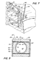
- Figure 3 is a partial cross section of the article as taken along lines 3-3 in Figure 2.
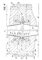
- Figure 4 is a partial cross section of a molding apparatus of the present invention.
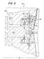
- Figure 5 is a partial cross section of a second embodiment of a molding apparatus of the present invention.
- Figure 6 is a cross section of a third embodiment of a molding apparatus of the present invention.
- Figure 7 is an isometric cross section of the molding apparatus shown in Figure 6.
- Figure 8 is a second cross section of the molding apparatus shown in Figure 7.
- Figure 9 is a cross section of the molding apparatus of Figure 8 taken along line 8-8.
- Article 10 is, for example, in the form of two containers 12 and 12′ which are simultaneously molded during a single molding operation.
- the two containers 12 and 12′ are joined together adjacent lips 14 and 14′.
- article 10 is separated, e.g., cut along a transverse plane substantially through its middle, such that containers 12 and 12′ are of equal dimension and the lips 14 and 14′ form the periphery of the open upper end thereof.
- Recessed lip 14 as contemplated by the present invention is shown in cross-section in Figure 3.
- Recessed lip 14 includes a generally U-shaped hollow member with an inner wall 18, an outer wall 16, and a curved lower wall 20.
- An upper wall 22 is formed over the U-shape by a layer of plastic folded inwardly toward the center of the container 12.
- the upper wall 22 is folded over the extension flange 23 between the body of the container 12 and the U-shaped portion.
- the folding over of wall 22 and flange 23 serves to increase the mechanical strength of the lip 14 and container 12.
- the lip 14 is provided with at least one vent 24 to allow pressurized air to escape from the hollow of the lip 14 and prevent the lip 14 from exploding after release of pressure within the mold during the molding process.
- Figure 4 illustrates a first embodiment of a molding apparatus 26 in accordance with the present invention.
- Apparatus 26 comprises two reciprocally movable mold halves 28 and 30.
- Left mold half 28 and right mold half 30 are arranged symmetrically on opposite sides of vertical plane Y-Y.
- Mold half 28 is a mirror image of mold half 30.
- Each mold half 28 and 30 includes two vertically reciprocally movable sections.
- Mold half 28 comprises Sections I and III.
- Mold half 30 comprises Sections II and IV.
- Each mold half section is positioned on opposite sides of a center ring member 34 and 34′, respectively. When the mold sections are closed (as illustrated, Sections III and IV), they define the shape of article 10.
- Mold half 28 will be described in detail below. Those skilled in the art will understand that this description applies equally well to mold half 30.
- Mold half 28 includes a plate 32.
- Center ring member 34 is fixed perpendicular to plate 32 and perpendicular to plane Y-Y.
- Center ring member 34 includes a separating member 36 which projects inwardly toward the center of the molding apparatus 26.
- Plate 32 is moveable horizontally. Sections I and III of mold 28 are slidably mounted on plate 32 via linear thrust bearings 38.
- Mold Sections I and III include a movable plate 40 having a surface 40A that rides on bearings 38. Plate 40 is capable of reciprocal movement toward and away from ring 34. Mold wall 42 is rigidly fixed to plate 40 along surface 40B. Plate 40 can be eliminated in which case mold wall 42 would be slidably mounted directly on the bearings 38. Lower and upper pinch-off plates (not shown) are fixed to the upper and lower surface of mold walls 42 of Sections I and III, respectively. The pinch-off plates are reciprocally movable perpendicular to the vertical Y-Y plane, toward and away from the center of the mold 26. The pinch-off plates cooperate to form a cylindrical bore at the base of the mold and provides clearance for flash from the parison and for the blow tube (not shown).
- the bottom pinch-off plates also include clearance on their inner surfaces for excess plastic extruded during the molding process.
- the pinch-off plates form a tight seal about the blow tube.
- Mold walls 42 and 42′ and pinch-off plates together define a cavity 44 defined as two frusto-conical forms which, when brought together, define the shape of article 10.
- the shape of the cavity 44 will correspond to the desired shape.
- a first insert member 46 is positioned within a recesses in the mold wall 42 proximal to center ring member 34.
- First insert member 46 forms the upper end of container 12 adjacent lip 14.
- First insert member 46 includes a channel 47 into which is placed a second insert member 48.
- First insert member 46 is preferably made of steel, but any metal with the properties similar to those of steel will suffice.
- Second insert member 48 is reciprocally movable within the channel 47 in the Y-Y direction. The first insert member 46 and is biased away from the interior of the channel 47 by coil springs 50 (only one spring 50 being shown for each mold section).
- Second insert member 48 is preferably made of bronze, but any metal having properties similar to those of bronze in relation to the materials of the first insert member 46 will suffice.
- Second insert member 48 is L-shaped in cross-section and is reciprocally slidable between a first position (Section I) and a second position (Section III).
- the L-shape forms a shoulder 52.
- Springs 50 bias second insert member 48 to the first position, i.e., out of the channel in ring member 46 when the mold is separated. Springs 50 maintain second insert member 48 in its projected position until the movement of the mold sections causes engagement of shoulder 52 with ring member 34.
- first insert 46 and second insert 48 initiate their movement toward the center ring member 34.
- the first insert 46 continues to move toward ring member 34 and separating member 36.
- This relative movement of the mold sections causes the parison 54 to form the hollow U-shaped lip 14 (see Section III).
- the relative spacing between the projection of separating member 36 and the vertical projection of first insert 46 is controlled to permit the overlap of flange 23 and upper wall 22 by the lip 14. This relationship is illustrated in Sections II and IV. Preferably these two portions weld together and seal the hollow of the U-shape.
- first insert member may be reduced so as to provide a gap between the formation of the upper wall 22 and the flange 23. This gap forms the vent 24 in the lip 14 area for release of pressure within the lip hollow during release of pressure in the mold cavity 44. During the separation of the parts of apparatus 26, the relative movement thereof is opposite that in forming the article 10.
- FIG. 5 illustrates a second embodiment of the molding apparatus 26′ as contemplated by the present invention.
- the apparatus 26′ shown in this Figure 5 includes a lever mechanism 58 to synchronize to formation of the lip 14.
- One end of lever 58 is fixed to the first insert member 46 at pivot 59.
- the opposite end of lever 58 is connected to push rod 60 at pivot 66.
- Post rod 60 as shown is attached by screw threads to center ring member 34.
- the push rod 60 need only contact center ring 34 for proper synchronization of the movement of inserts 46 and 48.
- a contact projection 61 is a contact projection 61.
- Contact projection 61 rids on flange 62.
- Flange 62 projects from a shaft 63 which is fixed at one end to second insert member 48. The opposite end of shaft 63 is mounted in mold wall 42. Shaft 63 is biased toward center ring 34 by spring 64 such that the flange 62 normally engages projection 61 on lever 58.
- first insert 46 will move toward ring member 34 at a speed less than twice that of the second insert member 48.
- both members reach center ring member 34 at substantially the same time.
- FIG. 6 and 7 Illustrated in Figures 6 and 7 is another alternate embodiment of a molding apparatus 26 ⁇ .
- This third embodiment includes a synchronized movement of the mold parts that is similar to that accomplished by apparatus 26' in Figure 5.
- one end of lever 68 contacts wear plate 70 on mold part 42.
- the opposite end of lever 68 contacts flange 82.
- Flange 82 is formed at one end of shaft 83.
- the opposite end of shaft 83 is fixed to center ring 34.
- Lever 68 is pivoted to second insert member 48 at pivot 84.
- the placement of pivot 84 is determined by the desired relative speed of the first insert 46 as compared to the second insert 48. Since the speed of second insert 48 is desired to be greater than one half the speed of first insert 46, the pivot should preferably be located no greater than one half the length of the lever 68 from the end thereof contacting wear plate 70 on mold part 42.
- first insert 46 and second insert 48 controls the flow of the parison 54 in the formation of the lip portion 14 of container 12.
- the relative movement of the mold parts allows the parison 54 to be rolled around the concave surface 48B on second insert 48. Control of this relative speed results in an even distribution of the parison 54 in the lip 14, particularly in the area of inner wall 18.
- the inner wall 18 of lip 14 may become somewhat elongated, and thus thinner, as compared to the other portions 16, 20, and 22 of the lip 14. This thinned area is caused by a stretching of the inner wall 18 area due to the relative progression of first insert 46 as compared to second insert 48.
- the relative speed of the inserts 46 and 48 cause the compression of the outer wall 16 without bunching and without the inner wall 18 becoming stretched.
- the arrival of the parts 46 and 48 into the desired position to form lip 14 is substantially simultaneous due to the relative speed of insert 48 being greater than one half of the speed of insert 46.
- This relative movement results in a lip 14 which is substantially uniform in formation and which does not include weakened areas resulting from wrinkled or improperly hardened plastic. For these reasons, these alternate embodiments 26′ and 26 ⁇ are preferred.
- Figures 8 and 9 illustrate means for releasing the molding apparatus 26 ⁇ once the article 10 has been molded.
- plates 32 and 40, mold wall 42, and center member 34 move in a horizontal direction away from the cavity 44.
- mold wall 42 moves in a vertical direction away from center member 34.
- the shoulder 52 of second insert member 48 in this embodiment is in direct contact with center member 34.
- the projection of first insert member 46 must clear the lower wall 20 of the lip 14 prior to its horizontal movement.
- a spring bolt 74 is placed in a channel 75 which extends through second insert 48 and terminates within first insert 46.
- a spring 76 is placed in channel 75.
- Spring 76 extends between plate 40 and an internal limit stop 72 within first insert member 46.
- the opposite end of spring bolt 74 includes a bolt head 74B which is retained within passageway 78 in insert 46.
- Passageway 78 provides for limited movement of the bolt head 74B upon horizontal movement of the plate 40.
- the compressed spring 76 keeps first members 46 from moving in the horizontal direction until bolt head 74B reaches the internal limit of passageway 78.
- insert portions 46 and 48 of the mold are free to move vertically with the mold wall 42.
- inserts 46 and 48 move horizontally with parts 40 and 42. This occurs after the projections of inserts 46 and 48 have cleared the lip 14.
- This relationship of the mold part movement permits the reduction in the number of actuators required for mold separation and increases the number of cycles that the apparatus 26 ⁇ may perform in a given amount of time.
Landscapes
- Engineering & Computer Science (AREA)
- Manufacturing & Machinery (AREA)
- Mechanical Engineering (AREA)
- Moulds For Moulding Plastics Or The Like (AREA)
- Blow-Moulding Or Thermoforming Of Plastics Or The Like (AREA)
Applications Claiming Priority (2)
| Application Number | Priority Date | Filing Date | Title |
|---|---|---|---|
| US462178 | 1990-01-08 | ||
| US07/462,178 US5051084A (en) | 1988-10-31 | 1990-01-08 | Reverse lip blow molding apparatus |
Publications (3)
| Publication Number | Publication Date |
|---|---|
| EP0437332A2 true EP0437332A2 (de) | 1991-07-17 |
| EP0437332A3 EP0437332A3 (en) | 1993-06-09 |
| EP0437332B1 EP0437332B1 (de) | 1996-05-29 |
Family
ID=23835454
Family Applications (1)
| Application Number | Title | Priority Date | Filing Date |
|---|---|---|---|
| EP91300087A Expired - Lifetime EP0437332B1 (de) | 1990-01-08 | 1991-01-07 | Blasformen eines Artikels mit überstehendem Rand |
Country Status (6)
| Country | Link |
|---|---|
| US (1) | US5051084A (de) |
| EP (1) | EP0437332B1 (de) |
| JP (1) | JPH04211918A (de) |
| CA (1) | CA2033273A1 (de) |
| DE (1) | DE69119790T2 (de) |
| MX (1) | MX172527B (de) |
Cited By (3)
| Publication number | Priority date | Publication date | Assignee | Title |
|---|---|---|---|---|
| US9221209B2 (en) | 2011-01-14 | 2015-12-29 | The Procter & Gamble Company | Process for the manufacture of a container |
| US9346200B2 (en) | 2011-01-14 | 2016-05-24 | The Procter & Gamble Company | Closure for a container |
| US9994368B2 (en) | 2012-10-30 | 2018-06-12 | The Procter & Gamble Company | Closure for a container |
Families Citing this family (11)
| Publication number | Priority date | Publication date | Assignee | Title |
|---|---|---|---|---|
| US5213753A (en) * | 1989-04-21 | 1993-05-25 | Mauser-Werke Gmbh | Method for compression molding flanges on a blow molded body to be severed into a vessel and lid |
| US5202078A (en) * | 1991-11-15 | 1993-04-13 | Lerio Corporation | Process and apparatus for manufacturing containers with thickened flanges and longitudinal reinforcing ribs and containers thereby |
| US5253996A (en) * | 1991-11-15 | 1993-10-19 | The Lerio Corporation | Apparatus for manufacturing containers with thickened flanges |
| EP0569192B1 (de) * | 1992-05-04 | 1997-03-26 | Cadillac Products Inc. | Aus einer Doppelbahn warmgeformte Struktur und Verfahren zu deren Herstellung |
| US5227114A (en) * | 1992-07-16 | 1993-07-13 | The Lerio Corporation | Process for manufacturing containers with thickened flanges |
| US5288453A (en) * | 1992-11-12 | 1994-02-22 | Custom Pak, Incorporated | Method for forming double walled integral hinge members in blowmolded plastic articles |
| USD361956S (en) | 1994-02-28 | 1995-09-05 | The Lerio Corporation | Plant container |
| RU2186683C1 (ru) * | 2001-05-28 | 2002-08-10 | Загороднюк Владимир Евгеньевич | Экструзионно-раздувная формовочная машина |
| US20080099964A1 (en) * | 2006-10-26 | 2008-05-01 | Nursery Supplies, Inc. | Thermoformed nursery container with a defined rim |
| US9149007B2 (en) | 2013-01-02 | 2015-10-06 | Nursery Supplies, Inc. | Blow molded nursery container with stiffened rim and flexible handles |
| FR3003793B1 (fr) * | 2013-03-27 | 2015-07-10 | Sidel Participations | Recipient a socle renforce et procede de fabrication d’un tel recipient |
Family Cites Families (24)
| Publication number | Priority date | Publication date | Assignee | Title |
|---|---|---|---|---|
| US2828789A (en) * | 1955-08-12 | 1958-04-01 | Wilbro Corp | Containers |
| BE580044A (de) * | 1958-07-26 | |||
| US3424829A (en) * | 1965-05-04 | 1969-01-28 | Phillips Petroleum Co | Method and apparatus for blow molding hollow articles with integrally molded hollow handles |
| US3428722A (en) * | 1966-09-16 | 1969-02-18 | American Can Co | Method and apparatus for blow molding hollow thermoplastic articles |
| FR1503960A (fr) * | 1966-10-20 | 1967-12-01 | Procédé et moule pour la réalisation d'une pièce creuse en matière plastique comportant une entretoise ou autre organe s'étendant à l'intérieur | |
| FR1540333A (fr) * | 1967-03-14 | 1968-09-27 | Corps creux et moules à coquilles permettant une fabrication multiple et simultanée au moyen d'une paraison de nappe tubulaire en matière plastique | |
| US3691267A (en) * | 1968-09-25 | 1972-09-12 | Hiraki Takehara | Sanitary process of packing a subject into a vessel |
| US3941542A (en) * | 1971-01-28 | 1976-03-02 | Owens-Illinois, Inc. | Apparatus for blow molding plastic articles |
| GB1469756A (en) * | 1973-06-05 | 1977-04-06 | Stoud Ltd D | Manufacture of disposable containers or cups |
| NL155229B (nl) * | 1973-09-10 | 1977-12-15 | Wiva Nv | Houder. |
| US4036926A (en) * | 1975-06-16 | 1977-07-19 | Owens-Illinois, Inc. | Method for blow molding a container having a concave bottom |
| US4022345A (en) * | 1976-03-15 | 1977-05-10 | Advanced Chemical Technology | Drum with handling rings |
| US4117062A (en) * | 1977-06-17 | 1978-09-26 | Owens-Illinois, Inc. | Method for making a plastic container adapted to be grasped by steel drum chime-handling devices |
| US4228122A (en) * | 1978-03-08 | 1980-10-14 | Mauser Kommandit-Gesellschaft | Method of manufacturing roller chimes for closed head drums |
| US4170623A (en) * | 1978-03-20 | 1979-10-09 | Greif Bros. Corporation | Method of blow molding an all plastic drum and compression molding a projection thereon |
| DE2815326C2 (de) * | 1978-04-08 | 1982-09-23 | Mauser KG, 5040 Brühl | Geblasenes Spundfaß |
| US4228916A (en) * | 1978-07-20 | 1980-10-21 | Standard Container Company | Plastic paint bucket with metal sealing ring |
| DE2914938C2 (de) * | 1979-04-12 | 1982-11-11 | Mauser-Werke GmbH, 5040 Brühl | Vorrichtung zum Blasformen eines Fasses |
| US4426416A (en) * | 1980-10-14 | 1984-01-17 | Plm Aktiebolag | Article of plastic material having a neck portion including annular protuberances with monoaxially oriented material |
| GB2093673A (en) * | 1981-03-04 | 1982-09-08 | Santaub Melvyn Derrick | Plant pot |
| DE3226872A1 (de) * | 1982-07-17 | 1984-01-19 | Mauser-Werke GmbH, 5040 Brühl | Verfahren zur herstellung eines hohlkoerpers |
| DE3721763A1 (de) * | 1987-04-02 | 1988-10-20 | Westphal & Lange Gmbh & Co Kg | Kunststoff-weithalsfass |
| DE3732898A1 (de) * | 1987-09-30 | 1989-04-20 | Mauser Werke Gmbh | Verfahren zur herstellung eines hohlkoerpers |
| US4938680A (en) * | 1988-10-31 | 1990-07-03 | Guarriello Henry J | Reverse lip blow molding apparatus |
-
1990
- 1990-01-08 US US07/462,178 patent/US5051084A/en not_active Expired - Lifetime
- 1990-12-27 CA CA002033273A patent/CA2033273A1/en not_active Abandoned
-
1991
- 1991-01-07 DE DE69119790T patent/DE69119790T2/de not_active Expired - Fee Related
- 1991-01-07 EP EP91300087A patent/EP0437332B1/de not_active Expired - Lifetime
- 1991-01-08 JP JP3011531A patent/JPH04211918A/ja active Pending
- 1991-01-08 MX MX024099A patent/MX172527B/es unknown
Cited By (3)
| Publication number | Priority date | Publication date | Assignee | Title |
|---|---|---|---|---|
| US9221209B2 (en) | 2011-01-14 | 2015-12-29 | The Procter & Gamble Company | Process for the manufacture of a container |
| US9346200B2 (en) | 2011-01-14 | 2016-05-24 | The Procter & Gamble Company | Closure for a container |
| US9994368B2 (en) | 2012-10-30 | 2018-06-12 | The Procter & Gamble Company | Closure for a container |
Also Published As
| Publication number | Publication date |
|---|---|
| EP0437332B1 (de) | 1996-05-29 |
| MX172527B (es) | 1993-12-17 |
| US5051084A (en) | 1991-09-24 |
| EP0437332A3 (en) | 1993-06-09 |
| DE69119790T2 (de) | 1996-10-24 |
| CA2033273A1 (en) | 1991-07-09 |
| DE69119790D1 (de) | 1996-07-04 |
| JPH04211918A (ja) | 1992-08-03 |
Similar Documents
| Publication | Publication Date | Title |
|---|---|---|
| US5364675A (en) | Reverse lip blow molded article | |
| EP0437332A2 (de) | Blasformen eines Artikels mit überstehendem Rand | |
| US4972963A (en) | Blow molded article with reverse lip | |
| US4769206A (en) | Method for producing a hollow body provided with a stand ring by blow moulding | |
| US3767747A (en) | Method for blow molding | |
| US5209891A (en) | Reverse lip blow molding | |
| US4938680A (en) | Reverse lip blow molding apparatus | |
| US4334852A (en) | Apparatus for blow molding a hollow plastic article having a relatively wide neck | |
| US3479421A (en) | Method of molding hollow bodies | |
| US3940225A (en) | Blow molding apparatus for staged inflation of an extruded parison | |
| US3371376A (en) | Apparatus for the production of hollow objects with relatively wide openings | |
| JP6840393B2 (ja) | 射出延伸ブロー成形機と中空成形体の製造方法 | |
| US3465071A (en) | Reduced neck article forming method and apparatus | |
| JPS6033657B2 (ja) | 射出成形用金型 | |
| EP0371341B1 (de) | Blasform zum Formen eines doppelwandigen Hohlkörpers | |
| US3669606A (en) | Apparatus for forming protrusions with enlarged head portions in thermoplastic sheet material | |
| US10022904B2 (en) | Blow molding process and apparatus | |
| US3752627A (en) | Device for manufacturing a hollow article of plastic material | |
| US5021209A (en) | Process for forming an extrusion-blow molded ultrathin container using a heat generating pinch off arrangement | |
| US3514509A (en) | Method of producing thin walled containers of thermoformable plastic | |
| EP0022343B1 (de) | Verfahren und Apparat zum Blasformen | |
| US20150097319A1 (en) | Method and Apparatus for In-Mold Finishing of Blow Molded Parts | |
| US5346665A (en) | Method of blow molding and blow molding system | |
| US3733384A (en) | Process for preventing fluid leakage in extrusion blow molding | |
| US12275181B2 (en) | Blow mold, stretch blow molder and method for forming a container |
Legal Events
| Date | Code | Title | Description |
|---|---|---|---|
| PUAI | Public reference made under article 153(3) epc to a published international application that has entered the european phase |
Free format text: ORIGINAL CODE: 0009012 |
|
| AK | Designated contracting states |
Kind code of ref document: A2 Designated state(s): DE FR GB IT |
|
| PUAL | Search report despatched |
Free format text: ORIGINAL CODE: 0009013 |
|
| AK | Designated contracting states |
Kind code of ref document: A3 Designated state(s): DE FR GB IT |
|
| 17P | Request for examination filed |
Effective date: 19931207 |
|
| 17Q | First examination report despatched |
Effective date: 19950327 |
|
| GRAH | Despatch of communication of intention to grant a patent |
Free format text: ORIGINAL CODE: EPIDOS IGRA |
|
| GRAA | (expected) grant |
Free format text: ORIGINAL CODE: 0009210 |
|
| AK | Designated contracting states |
Kind code of ref document: B1 Designated state(s): DE FR GB IT |
|
| ET | Fr: translation filed | ||
| REF | Corresponds to: |
Ref document number: 69119790 Country of ref document: DE Date of ref document: 19960704 |
|
| ITF | It: translation for a ep patent filed | ||
| PLBE | No opposition filed within time limit |
Free format text: ORIGINAL CODE: 0009261 |
|
| STAA | Information on the status of an ep patent application or granted ep patent |
Free format text: STATUS: NO OPPOSITION FILED WITHIN TIME LIMIT |
|
| 26N | No opposition filed | ||
| REG | Reference to a national code |
Ref country code: GB Ref legal event code: IF02 |
|
| PGFP | Annual fee paid to national office [announced via postgrant information from national office to epo] |
Ref country code: IT Payment date: 20060131 Year of fee payment: 16 |
|
| PGFP | Annual fee paid to national office [announced via postgrant information from national office to epo] |
Ref country code: GB Payment date: 20070125 Year of fee payment: 17 |
|
| PGFP | Annual fee paid to national office [announced via postgrant information from national office to epo] |
Ref country code: DE Payment date: 20070228 Year of fee payment: 17 |
|
| PGFP | Annual fee paid to national office [announced via postgrant information from national office to epo] |
Ref country code: FR Payment date: 20070117 Year of fee payment: 17 |
|
| GBPC | Gb: european patent ceased through non-payment of renewal fee |
Effective date: 20080107 |
|
| PG25 | Lapsed in a contracting state [announced via postgrant information from national office to epo] |
Ref country code: DE Free format text: LAPSE BECAUSE OF NON-PAYMENT OF DUE FEES Effective date: 20080801 |
|
| REG | Reference to a national code |
Ref country code: FR Ref legal event code: ST Effective date: 20081029 |
|
| PG25 | Lapsed in a contracting state [announced via postgrant information from national office to epo] |
Ref country code: GB Free format text: LAPSE BECAUSE OF NON-PAYMENT OF DUE FEES Effective date: 20080107 |
|
| PG25 | Lapsed in a contracting state [announced via postgrant information from national office to epo] |
Ref country code: FR Free format text: LAPSE BECAUSE OF NON-PAYMENT OF DUE FEES Effective date: 20080131 |
|
| PG25 | Lapsed in a contracting state [announced via postgrant information from national office to epo] |
Ref country code: IT Free format text: LAPSE BECAUSE OF NON-PAYMENT OF DUE FEES Effective date: 20070107 |