EP0436853B1 - Flüssigkristallanzeige mit faseroptischer Frontplatte - Google Patents
Flüssigkristallanzeige mit faseroptischer Frontplatte Download PDFInfo
- Publication number
- EP0436853B1 EP0436853B1 EP90123816A EP90123816A EP0436853B1 EP 0436853 B1 EP0436853 B1 EP 0436853B1 EP 90123816 A EP90123816 A EP 90123816A EP 90123816 A EP90123816 A EP 90123816A EP 0436853 B1 EP0436853 B1 EP 0436853B1
- Authority
- EP
- European Patent Office
- Prior art keywords
- faceplate
- light
- liquid crystal
- display
- fiber
- Prior art date
- Legal status (The legal status is an assumption and is not a legal conclusion. Google has not performed a legal analysis and makes no representation as to the accuracy of the status listed.)
- Expired - Lifetime
Links
- 239000000835 fiber Substances 0.000 title claims description 58
- 239000004973 liquid crystal related substance Substances 0.000 title claims description 40
- 239000013307 optical fiber Substances 0.000 claims description 12
- 239000011521 glass Substances 0.000 claims description 7
- 230000002708 enhancing effect Effects 0.000 claims description 2
- 239000010410 layer Substances 0.000 description 13
- 238000005286 illumination Methods 0.000 description 11
- 210000004027 cell Anatomy 0.000 description 10
- 239000000463 material Substances 0.000 description 10
- 230000009471 action Effects 0.000 description 7
- 238000010276 construction Methods 0.000 description 4
- 238000009792 diffusion process Methods 0.000 description 4
- 239000011248 coating agent Substances 0.000 description 3
- 238000000576 coating method Methods 0.000 description 3
- 230000000694 effects Effects 0.000 description 3
- VYPSYNLAJGMNEJ-UHFFFAOYSA-N Silicium dioxide Chemical compound O=[Si]=O VYPSYNLAJGMNEJ-UHFFFAOYSA-N 0.000 description 2
- 230000005684 electric field Effects 0.000 description 2
- 230000004313 glare Effects 0.000 description 2
- 230000006872 improvement Effects 0.000 description 2
- 230000028161 membrane depolarization Effects 0.000 description 2
- 230000003287 optical effect Effects 0.000 description 2
- 230000010287 polarization Effects 0.000 description 2
- 238000002310 reflectometry Methods 0.000 description 2
- 239000011358 absorbing material Substances 0.000 description 1
- 230000003190 augmentative effect Effects 0.000 description 1
- 210000002858 crystal cell Anatomy 0.000 description 1
- 230000003247 decreasing effect Effects 0.000 description 1
- 230000008030 elimination Effects 0.000 description 1
- 238000003379 elimination reaction Methods 0.000 description 1
- 238000005516 engineering process Methods 0.000 description 1
- 210000000887 face Anatomy 0.000 description 1
- 239000005262 ferroelectric liquid crystals (FLCs) Substances 0.000 description 1
- 239000002346 layers by function Substances 0.000 description 1
- 238000000034 method Methods 0.000 description 1
- 229920000642 polymer Polymers 0.000 description 1
- 230000008569 process Effects 0.000 description 1
- 230000001902 propagating effect Effects 0.000 description 1
- 230000009467 reduction Effects 0.000 description 1
- 230000004044 response Effects 0.000 description 1
- 235000012239 silicon dioxide Nutrition 0.000 description 1
- 239000000377 silicon dioxide Substances 0.000 description 1
- 239000010409 thin film Substances 0.000 description 1
- 230000007704 transition Effects 0.000 description 1
Images


Classifications
-
- G—PHYSICS
- G02—OPTICS
- G02F—OPTICAL DEVICES OR ARRANGEMENTS FOR THE CONTROL OF LIGHT BY MODIFICATION OF THE OPTICAL PROPERTIES OF THE MEDIA OF THE ELEMENTS INVOLVED THEREIN; NON-LINEAR OPTICS; FREQUENCY-CHANGING OF LIGHT; OPTICAL LOGIC ELEMENTS; OPTICAL ANALOGUE/DIGITAL CONVERTERS
- G02F1/00—Devices or arrangements for the control of the intensity, colour, phase, polarisation or direction of light arriving from an independent light source, e.g. switching, gating or modulating; Non-linear optics
- G02F1/01—Devices or arrangements for the control of the intensity, colour, phase, polarisation or direction of light arriving from an independent light source, e.g. switching, gating or modulating; Non-linear optics for the control of the intensity, phase, polarisation or colour
- G02F1/13—Devices or arrangements for the control of the intensity, colour, phase, polarisation or direction of light arriving from an independent light source, e.g. switching, gating or modulating; Non-linear optics for the control of the intensity, phase, polarisation or colour based on liquid crystals, e.g. single liquid crystal display cells
- G02F1/133—Constructional arrangements; Operation of liquid crystal cells; Circuit arrangements
- G02F1/1333—Constructional arrangements; Manufacturing methods
- G02F1/1335—Structural association of cells with optical devices, e.g. polarisers or reflectors
- G02F1/133524—Light-guides, e.g. fibre-optic bundles, louvered or jalousie light-guides
Definitions
- This invention relates generally to liquid crystal display (LCD) systems, and particularly to LCD systems augmented with a specialized fiber optic faceplate enhanced with means for polarizing ambient light passing through the faceplate toward and away from a surface of the LCD system.
- LCD liquid crystal display
- Typical prior art flat panel liquid crystal display systems are described in "Flat-Panel Displays Come on Strong in Speed, Resolution and Color," Computer Design, February 1, 1989, pages 65 through 82.
- Operation and performance of direct multiplexed liquid crystal displays including the twisted nematic (TN), the supertwisted birefringence effect (SBE), and the surface-stabilized ferroelectric liquid-crystal (SSFLC) display, are described by Scheffer “Direct-Multiplex Liquid-Crystal Displays," Seminar 4, Society for Information Display (SID) International Symposium Seminar Lecture Notes, Vol. 1, May 11, 1987, pages 4.1 through 4.34.
- LCDs which are intended for use in portable systems are of the reflection type in order to make use of available ambient light for illumination rather than incurring the weight, bulk, and power consumption characteristic of active backlighting.
- Such displays include a liquid crystal layer which is sandwiched between transparent front and back electrodes, and a specular or semi-specular (i.e., mirror-like) surface placed behind the display to enhance reflection.
- the system has an off-state, i.e., no voltage is applied between the front and back electrodes, and an on-state, i.e., such a voltage is applied.
- the Hoffman patent pertains exclusively to LCDs of the dynamic scattering type.
- this type of LCD When this type of LCD is in the off-state the liquid crystal is clear, permitting light to pass through and be reflected back out by the reflective back electrode. In the on-state the liquid crystal scatters light increasingly in proportion to increasing applied voltage.
- This mode of controlling the light transmissivity of the liquid crystal material in response to the applied voltage is called the “dynamic scatter mode” (when light is transmitted through the LCD) and the “reflective dynamic scatter mode” (when light is reflected out the same side of the LCD).
- contrast defined here as the brightness ratio of the on-state to the off-state.
- the problem with this particular art is how to reduce excessive levels of incident light emanating from unwanted light sources which are positioned outside the viewing angle of the LCD screen. Contrast desirably increases if these unwanted light sources can be neutralized.
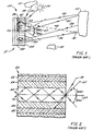
- FIGURE 1 shows a direct view liquid crystal image display system 20 viewed directly under ambient light from a source of light 22 such as a bright sky or brightly lit room (not shown).
- a source of light 22 such as a bright sky or brightly lit room (not shown).
- Light rays 24, 25, and 26 from light source 22 hit a fiber optic faceplate 28 within an acceptance cone Theta max [herein, T(max)] of faceplate 28.
- Rays 24, 25, 26 are transmitted to a liquid crystal layer 30 of a liquid crystal display device 31 over which faceplate 28 lies.
- T(max) is measured with respect to an axis 27 which is parallel to the horizontal light-propagating axis (not labelled) of the optical fibers comprising fiber optic faceplate 28 and perpendicular to the face of faceplate 28.
- existing technology configures system 20 so that light enters and leaves faceplate 28 only within a well defined faceplate 28 acceptance angle T(max). By this approach, stray light is absorbed by faceplate 28.
- faceplate 28 by absorbing light from sources outside the acceptance cone T(max) of faceplate 28, such as a ray 56 from the Sun 54 and a ray 58 from light source 52, faceplate 28 prevents undesirable loss of image contrast of the LCD images with respect to ambient light generated by such light sources as 22, 50, 52, and 54.
- FIGURE 2 illustrates in cross-section a single optical fiber 60 of the type bundled together to make up faceplate 28 shown in Fig. 1.
- Faceplate 28 is formed with many parallel optical fibers 60 which are fused together.
- Each fiber 60 has a light-transparent core 62 having an index of refraction n1, covered with a light-transparent sheath 64 having an index of refraction n2 which is less than n1, which in turn is covered with an optically absorbing material 66.
- An incident light ray 25 falling within the acceptance angle T(max) to optical fiber axis 27 propagates through core 62 by the well known phenomenon of multiple total internal reflections from a boundary 70 existing between core 62 and sheath 64.
- an incident light ray 58 falling outside incidence angle T(max) will not be totally reflected, but instead will propagate through boundary 70 into transparent sheath 64, finally to be absorbed by light absorbing layer or material 66.
- the function of the fiber plate in the Hoffman LCD is to absorb all light which strikes the display outside the viewing angle of the display (defined as the angle over which the display provides an image of acceptable contrast), thereby reducing stray light and enhancing the contrast of the display.
- the dynamic scattering type of LCD has not become a commercially important device due to its relatively limited viewing angle and poor contrast.
- Twisted nematic (TN) and super twisted nematic (STN) LCDs have become commercially important in the last 10 or so years largely because they offer improved contrast and viewing angle compared to previous types, such as the dynamic scattering LCD with or without the Hoffman improvements.
- TN and STN displays depend upon the action of polarizers on polarized light propagating within the display rather than scattering to produce the light and dark areas of their images.
- the black interstitial material in the Hoffman fiber plate causes a sharp transition from a normal display appearance to a completely black display appearance with increasing angle which can be annoying to the viewer of a TN or STN type LCD. This is because the contrast of TN and STN LCDs degrades slowly with angle, and, although viewing contrast may not be fully acceptable at high angles, a viewer may be able to determine the general nature of what is being displayed or merely that something is being displayed, even when he views the display at high angles.
- Hoffman teaches the application of a fiber plate composed of fibers each having as low numerical aperture as possible and restricting the viewing angle by means of the black interstitial material as much as possible in order to reject as much stray light as possible.
- the present invention teaches the application of fiber plates having as high a numerical aperture as possible and permitting as wide a viewing angle as possible in order to gather as much ambient light as possible to illuminate the display.
- Fig. 3 shows a typical prior art reflective liquid crystal display utilizing polarizers.
- LCD 300 includes a layer of liquid crystal material 301 sandwiched between drive matrices 302a and 302b for applying electric fields to appropriate locations within the layer of liquid crystal material 301.
- selected pixel 304 (shown as dark, but may actually appear dark or light depending upon polarizer orientation) is shown within the layer of liquid crystal material 301, caused by an appropriate electric field in that location applied across that portion of liquid crystal material 301 by matrices 302a and 302b.
- Glass plates 303a and 303b serve to support drive matrices 302a and 302b.
- polarizers 305a and 305b are formed on the other sides of glass plates 303a and 303b, respectively.
- Polarizer 305a serves as the exposed surface of liquid crystal display 300
- polarizer 305b faces semi-diffused mirror 307, separated from polarizer 305b by gap 306 which may be conveniently filled up by a glass plate.
- mirror 307 is formed as an aluminized coating on the surface of polarizer 305b which is not in contact with glass plate 303b.
- Extensions of rays 308-2 and 309-2 cross at 310, and hence appear to an observer to have come from 310. Also, since both rays pass through the location of the selected pixel 304, the intensity of both rays is modulated by the action of the display to be the same as that of the selected pixel 304.
- ghost image 310 is thus a virtual image in the geometrical optics sense of the selected pixel 304 lying behind 304 and, depending upon the observer's viewing position, may appear laterally displaced from 304 as well due to viewing parallax.
- a TN liquid crystal displays have been described, which comprise a liquid crystal layer sandwiched between a fiber optic faceplate containing a bundle of optical fibers each of which being perpendicular to an inner surface of said faceplate.
- the configuration of the open end of each fiber substantially corresponds to that of an image element (pixel) in order to avoid reduction of luminance and contrast.
- the problem underlying the invention is to avoid the disadvantages of the prior art displays as described above and to provide a display apparatus allowing ambient light from a much wider range of incidendent angles to illuminate the display apparatus and at the same time improves the visibility of the characters to be shown to a viewer even in difficult lighting situations.
- a novel liquid crystal display which includes a layer of liquid crystal material, one or more polarizers, and a fiber optic faceplate.
- the fiber optic faceplate serves to allow ambient light from a much wider range of incident angles to illuminate the LCD than would be the case with prior art LCDs, and allows the viewer to position himself so as to avoid front surface glare and still see the display brightly illuminated, even in difficult lighting situations.
- Fig. 1 depicts the operation of a prior art liquid crystal display, without polarizers, but using a fiber optic faceplate;
- Fig. 2 depicts the operation of a fiber contained within a fiber optic faceplate of Fig. 1;
- Fig. 3 depicts a prior art liquid crystal display utilizing polarizers, and the ghost image formed therewith;
- Figs. 4a through 4c depict the liquid crystal display of Fig. 3, and the angle over which incident light may serve to illuminate the LCD;
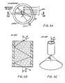
- Figs. 5a through 5c depict the operation of a single fiber used in the fiber faceplate of the present invention
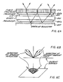
- Figs. 6a through 6c depict the operation of one embodiment of an LCD display constructed in accordance with the teachings of this invention, and the range of angles over which ambient light serves to illuminate the LCD;
- Fig. 7 depicts one embodiment of an LCD constructed in accordance with the teachings of this invention and the elimination of the ghost image obtained therewith.
- the fiber faceplate LCD of this invention appears more brightly illuminated than a conventional reflective LCD under a wide range of ambient lighting conditions due to the superior light diffusion characteristics of the fiber faceplate. To understand why this is the case, consider a prior art reflective LCD shown in Fig. 4a (in which the drive electrode and alignment layers, well known in the art, are omitted for clarity).
- the apparent background illumination is reflected ambient light.
- a ray of ambient light entering the conventional display at A After passing through the display cell, the ray emerges at B and is then reflected by a semi-diffuse mirror at C. After reflection the light present in the original ray is spread over a cone with half-angle ⁇ due to the diffusing action of mirror 307. This is shown in the two-dimensional polar plot of reflectivity of Fig. 4b, and the three-dimensional polar plot of reflectivity of Fig. 4c. The axis of this cone is coincident with the ray C-D which emerges from the display at the same angle as would the incident ray A-C, were the reflection purely specular in nature.
- the cone describing the intensity of the reflected illumination as a function of angle is an article of revolution about the direction of specular reflection
- the angle ⁇ is large, only a relative few of the typical multiplicity of ambient light sources can contribute illumination. Due to the nature of the diffuse scattering process, however, light scattered at large angles tends to be depolarized. The light exiting the cell at B has been polarized by the action of the LC cell.
- Figure 5b depicts a side view of the optical fiber of Figure 5a
- Figure 5c depicts in three dimensions the operation of the optical fiber of Figures 5a and 5b, showing that light incident from one direction is converted into a hollow cone of light having an apex angle equal to the incident angle.
- a fiber faceplate LCD of this invention shown diagrammatically in Fig. 6a (again, with the drive electrode and alignment layers omitted for clarity). Incident illumination from a single direction will be spread into a hollow cone by the action of the individual fibers of fiber faceplate 619, as just described. Upon passage through the LC cell it encounters specular reflector 307 which sends it back through the cell without depolarization and the attendant loss in intensity. The second passage through the fiber faceplate 619 results in a second azimuthal diffusion and the same hollow conical far field pattern described above.
- Fig. 7 depicts one embodiment of a fiber faceplate LCD constructed in accordance with the teachings of this invention, and how it substantially eliminates the ghost image.
- rays 701-2 and 702-2 encounter entirely different fibers than did 701-1 and 702-1 initially, and ray 701-2 encounters an entirely different fiber than does ray 702-2. Also rays 701-2 and 702-2 strike the fibers through which they pass out of the display at random locations within the fibers' cores, depending upon the incident angles and azimuths (parameters ⁇ and ⁇ in Figs. 5a-c) of rays 701-1 and 702-1. Exiting rays 701-3 and 702-3 are thus randomized in their exiting azimuths, as explained previously in the descriptions of Figs. 5a-c, and do not in general appear to have come from a single region of space, i.e., a ghost image.
- the light which ordinarily would be concentrated in a ghost image is smeared out by the diffusing effect of a second passage through the fiber faceplate and now forms a much larger and more diffuse shadow surrounding the selected pixel than in the case of the conventional LCD of Fig. 3.
- This larger and more diffuse shadow is less visible to the viewer than the ghost image of Fig. 3 in two ways.
- the shadow is largely intermixed with light which passed through nearby regions of the display, and hence its maximum lightness or darkness, depending upon the optical state of selected pixel 304, is not very different from that of the surrounding areas of the display.
- the shadow is substantially spatially diffused, like an out-of-focus image, and hence is not easily and clearly seen by the viewer as containing any information.
- the thickness of polarizer 605a must be small compared with the size of a display pixel.
- polarizer 605a is formed of a thin layer (typically within the range of approximately 0.5 to 100 ⁇ m) in order to present a sharp viewable image 720 when used with typical display pixel spacings of 100 to 400 ⁇ m.
- Thin polarizer 605a can be fabricated using an aligned organic dye, such as is described in the aforementioned Dryer patents.
- polarizer 605a is fabricated using the 105MS polarizer coating available from Da-Lite Screen Corporation of Cincinnati, Ohio.
- an overcoating layer between the polarizer coating and the other functional layers of the liquid crystal cell may be required, such as Da-Lite Corp's special polymer overcoating or a thin film overcoating of a compatible material such as silicon dioxide.
- Fiber faceplate 619 can be fabricated to a thickness in the range of approximately 0.7 to 1.1 millimeters, having individual fibers in the range of 6 to 25 ⁇ m. In one embodiment, fiber faceplate 619 is made approximately of 0.66 na clear fused glass optical fiberplate available from Incom, Inc. of Southbridge, Massachusetts.
- a novel LCD structure including a fiber faceplate (a) which does not degrade the viewing angle, contrast, and other operating features of the liquid crystal element itself, (b) which provides a wider angle over which ambient light is received for the purposes of illumination, and (c) which provides that the viewer need not be close to a position that would cause specularly reflected ambient light to fall in the viewer's eyes.
- teachings of this invention are useful not only for liquid crystal displays including polarizers on both sides of the liquid crystal, but also those liquid crystal displays which include at least one polarizer, such as those liquid crystal displays which include a polarizer only on the viewer side of the liquid crystal.
- the teachings of this invention are also applicable to those liquid crystal displays which, in addition to one or more polarizers, also include one or more birefringent elements serving to convert light between elliptical polarization and linear polarization.
Landscapes
- Physics & Mathematics (AREA)
- Nonlinear Science (AREA)
- Mathematical Physics (AREA)
- Chemical & Material Sciences (AREA)
- Crystallography & Structural Chemistry (AREA)
- General Physics & Mathematics (AREA)
- Optics & Photonics (AREA)
- Liquid Crystal (AREA)
- Devices For Indicating Variable Information By Combining Individual Elements (AREA)
- Light Guides In General And Applications Therefor (AREA)
- Optical Fibers, Optical Fiber Cores, And Optical Fiber Bundles (AREA)
Claims (7)
- Flüssigkristall-Anzeigevorrichtung zum Anzeigen mehrerer Zeichenbilder, welche bei Anwesenheit einer externen Lichtquelle arbeiten kann, wobei die Bilder auf einer im wesentlichen ebenen, lichtdurchlässigen Schirmplatte (619) sichtbar sind und die Zeichenbilder aus mehreren Pixeln gebildet werden, welche von einem Betrachter betrachtet werden, der von der Vorderseite der Schirmplatte auf die Zeichen sieht, bei dera. die Schirmplatte (619) eine äußere Oberfläche und eine innere Oberfläche aufweist und aus einem Bündel aus mehreren optischen Fasern oder Röhren gebildet wird, die im wesentlichen parallel zueinander, jedoch senkrecht zu der inneren Oberfläche ausgerichtet sind, wobei jede Faser oder Röhre eine Breite hat, die wesentlich kleiner als die Breite jedes Pixels ist;b. eine Polarisiervorrichtung (605a) hinter und im wesentlichen koplanar zu der inneren Oberfläche der Schirmplatte angeordnet ist, um das durch die Schirmplatte (619) hindurchgehende Licht zu polarisieren;c. Flüssigkristall-Anzeigemittel (601) hinter und im wesentlichen koplanar zu der inneren Oberfläche der Schirmplatte angeordnet sind, um die Zeichen zu erzeugen; undd. ein spiegelnder Reflektor (607) hinter und im wesentlichen koplanar zu der inneren Oberfläche der Schirmplatte (619) angeordnet ist, um das durch die Schirmplatte hindurchgehende Licht zu reflektieren.
- Vorrichtung nach Anspruch 1, dadurch gekennzeichnet, daß die Polarisiervorrichtung (605a) einen Polarisator aufweist, dessen Dicke innerhalb des Bereiches von etwa 0,5 bis 25 Mikrometern liegt.
- Vorrichtung nach Anspruch 1 oder 2, dadurch gekennzeichnet, daß die Polarisiervorrichtung (605a) einen Polarisator mit einem organischen Farbmittel aufweist.
- Vorrichtung nach einem der Ansprüche 1 bis 3, dadurch gekennzeichnet, daß die Schirmplatte (619) mit einer Dicke im Bereich von etwa 0,7 bis 1,1 Millimetern hergestellt ist.
- Vorrichtung nach einem der Ansprüche 1 bis 4, dadurch gekennzeichnet, daß die optischen Fasern oder Röhren Glas aufweisen.
- Vorrichtung nach einem der Ansprüche 1 bis 5, dadurch gekennzeichnet, daß die optischen Fasern oder Röhren eine numerische Apertur von etwa 0,66 aufweisen.
- Vorrichtung nach einem der Ansprüche 1 bis 6, dadurch gekennzeichnet, daß eine Hülle, welche jede der optischen Fasern oder Röhren längs ihrer Längsachse umschließt, so ausgebildet ist, daß sie das Umgebungslicht, wenn ein solches auf die Schirmplatte auftrifft, innerhalb der Schirmplatte (619) azimutal streut, wodurch die Sichtbarkeit des auf der Vorderseite der Schirmplatte dargestellten Bildes verbessert wird.
Applications Claiming Priority (2)
| Application Number | Priority Date | Filing Date | Title |
|---|---|---|---|
| US462679 | 1990-01-09 | ||
| US07/462,679 US5035490A (en) | 1990-01-09 | 1990-01-09 | Fiber optic |
Publications (3)
| Publication Number | Publication Date |
|---|---|
| EP0436853A2 EP0436853A2 (de) | 1991-07-17 |
| EP0436853A3 EP0436853A3 (en) | 1992-03-25 |
| EP0436853B1 true EP0436853B1 (de) | 1996-05-29 |
Family
ID=23837372
Family Applications (1)
| Application Number | Title | Priority Date | Filing Date |
|---|---|---|---|
| EP90123816A Expired - Lifetime EP0436853B1 (de) | 1990-01-09 | 1990-12-11 | Flüssigkristallanzeige mit faseroptischer Frontplatte |
Country Status (4)
| Country | Link |
|---|---|
| US (1) | US5035490A (de) |
| EP (1) | EP0436853B1 (de) |
| JP (1) | JP3203000B2 (de) |
| DE (1) | DE69027196T2 (de) |
Families Citing this family (21)
| Publication number | Priority date | Publication date | Assignee | Title |
|---|---|---|---|---|
| US5181130A (en) * | 1990-01-09 | 1993-01-19 | Hewlett-Packard Company | Fiber optic faceplate liquid crystal display |
| EP0525755A1 (de) * | 1991-07-30 | 1993-02-03 | Nitto Denko Corporation | Flüssigkristallanzeige |
| EP0618476A1 (de) * | 1993-03-31 | 1994-10-05 | Hughes Aircraft Company | Durchlicht-Projektionsschirm mit Unterdrückung von ausser-axialem Sonnenlicht |
| US5594561A (en) * | 1993-03-31 | 1997-01-14 | Palomar Technologies Corporation | Flat panel display with elliptical diffuser and fiber optic plate |
| JP3144607B2 (ja) * | 1993-04-09 | 2001-03-12 | 富士写真フイルム株式会社 | 光スイッチング素子 |
| US5329386A (en) * | 1993-04-13 | 1994-07-12 | Hewlett-Packard Company | Fiber-optic faceplate with tilted fibers |
| US5442467A (en) * | 1994-03-21 | 1995-08-15 | Xerox Corporation | Enhanced off-axis viewing performance and luminous efficiency of a liquid crystal display employing fiberoptic faceplate elements |
| US5629784A (en) * | 1994-04-12 | 1997-05-13 | Ois Optical Imaging Systems, Inc. | Liquid crystal display with holographic diffuser and prism sheet on viewer side |
| TW343290B (en) * | 1994-06-09 | 1998-10-21 | Hitachi Ltd | Reflection type liquid crystal display device and reflection type color liquid crystal display device |
| US5521726A (en) * | 1994-08-26 | 1996-05-28 | Alliedsignal Inc. | Polarizer with an array of tapered waveguides |
| JPH095745A (ja) * | 1995-06-07 | 1997-01-10 | Xerox Corp | カラー液晶ディスプレイ装置の光ファイバフェースプレート |
| TW329500B (en) | 1995-11-14 | 1998-04-11 | Handotai Energy Kenkyusho Kk | Electro-optical device |
| JPH09146108A (ja) * | 1995-11-17 | 1997-06-06 | Semiconductor Energy Lab Co Ltd | 液晶表示装置およびその駆動方法 |
| JP3708620B2 (ja) * | 1996-03-01 | 2005-10-19 | 株式会社半導体エネルギー研究所 | アクティブマトリクス型液晶電気光学装置 |
| US6339463B1 (en) | 1997-03-27 | 2002-01-15 | Xerox Corporation | Enhanced viewing angle performance on non-polarizer based color reflective liquid crystal display using a fiber-optic faceplate |
| US5963284A (en) * | 1998-04-01 | 1999-10-05 | Ois Optical Imaging Systems, Inc. | LCD with diffuser having diffusing particles therein located between polarizers |
| GB0010697D0 (en) * | 2000-05-03 | 2000-06-28 | Microsharp Corp Limited | Reflective light diffuser |
| JP4703887B2 (ja) * | 2001-04-27 | 2011-06-15 | 株式会社半導体エネルギー研究所 | 画像表示装置 |
| US7110175B2 (en) * | 2004-02-27 | 2006-09-19 | Bose Corporation | Display screens |
| US20060251365A1 (en) * | 2005-05-04 | 2006-11-09 | Brewer Donald R | Watch fiber optic image guide |
| US8717660B2 (en) | 2012-07-03 | 2014-05-06 | Qualcomm Mems Technologies, Inc. | Annulus scattering diffuser for reflective display |
Family Cites Families (11)
| Publication number | Priority date | Publication date | Assignee | Title |
|---|---|---|---|---|
| DE2461239A1 (de) * | 1974-12-23 | 1976-06-24 | Berkel Patent Nv | Vorrichtung zur digitalen anzeige von messdaten, insbesondere bei einer waage |
| JPS5464494A (en) * | 1977-10-31 | 1979-05-24 | Sharp Corp | Liquid crystal display unit |
| JPS55110217A (en) * | 1979-02-19 | 1980-08-25 | Sharp Corp | Driving system of liquid crystal display device |
| JPS5938591B2 (ja) * | 1979-02-20 | 1984-09-18 | シャープ株式会社 | 液晶表示装置 |
| US4241984A (en) * | 1979-06-04 | 1980-12-30 | Timex Corporation | Simplified field effect, twisted nematic liquid crystal display construction |
| US4349817A (en) * | 1980-01-28 | 1982-09-14 | Hoffman William C | Liquid crystal display system using fiber optic faceplates |
| JPS56117217A (en) * | 1980-02-21 | 1981-09-14 | Sharp Corp | Liquid-crystal display recorder |
| US4344668A (en) * | 1980-03-17 | 1982-08-17 | Hughes Aircraft Company | Fiber optic light traps for electro-optical display devices |
| EP0130492A3 (de) * | 1983-07-01 | 1987-07-15 | Koninklijke Philips Electronics N.V. | Flüssigkristallanzeige |
| US4674840A (en) * | 1983-12-22 | 1987-06-23 | Polaroid Corporation, Patent Dept. | Liquid crystal display with polarizer and biaxial birefringent support |
| US4859037A (en) * | 1986-02-18 | 1989-08-22 | Seiko Epson Corporation | Liquid crystal electrically-controlled birefringence display devices with improved contrast |
-
1990
- 1990-01-09 US US07/462,679 patent/US5035490A/en not_active Expired - Lifetime
- 1990-12-11 EP EP90123816A patent/EP0436853B1/de not_active Expired - Lifetime
- 1990-12-11 DE DE69027196T patent/DE69027196T2/de not_active Expired - Fee Related
-
1991
- 1991-01-09 JP JP01273991A patent/JP3203000B2/ja not_active Expired - Fee Related
Also Published As
| Publication number | Publication date |
|---|---|
| DE69027196T2 (de) | 1996-11-28 |
| EP0436853A3 (en) | 1992-03-25 |
| JP3203000B2 (ja) | 2001-08-27 |
| EP0436853A2 (de) | 1991-07-17 |
| US5035490A (en) | 1991-07-30 |
| JPH04212124A (ja) | 1992-08-03 |
| DE69027196D1 (de) | 1996-07-04 |
Similar Documents
| Publication | Publication Date | Title |
|---|---|---|
| EP0436853B1 (de) | Flüssigkristallanzeige mit faseroptischer Frontplatte | |
| US5181130A (en) | Fiber optic faceplate liquid crystal display | |
| US5956107A (en) | Diffusion optical guide plate, and backlight source and liquid crystal display apparatus using the same | |
| EP0674209B1 (de) | Flüssigkristalanzeige unter Verwendung faseroptischer Frontplattenelemente | |
| GB2306229A (en) | Diffusely reflective display cell | |
| JPH06194653A (ja) | トランスフレクティブ非放射表示装置 | |
| KR20050071629A (ko) | 양면 투시가 가능한 액정표시장치 및 이를 이용하는휴대장치 | |
| KR100870844B1 (ko) | 방현막을 포함하는 디스플레이 유닛 | |
| JPH08220519A (ja) | 拡散スクリーン及びそれを用いた液晶表示装置 | |
| EP1245995A2 (de) | Flüssigkristallanzeige | |
| US6211933B1 (en) | Reflective type liquid crystal display with scattering polarizer | |
| US7564518B2 (en) | Reflective cholesteric displays employing circular polarizers with the polarity of the front polarizer opposite to both the back polarizer and the bragg reflection | |
| JP3557313B2 (ja) | 液晶表示スクリーン | |
| JPH0675218A (ja) | 液晶表示パネル | |
| JP2000019490A (ja) | 反射型高分子分散型液晶表示装置 | |
| JPH09133920A (ja) | 透過型電気光学変調器用逆光照明システム及び逆光照明システムを有する表示装置 | |
| JP2003005181A (ja) | 液晶表示装置 | |
| RU2454689C2 (ru) | Модуль задней подсветки и жидкокристаллическое дисплейное устройство | |
| JPH09146093A (ja) | 照明装置およびそれを用いた液晶表示装置 | |
| JPH07333606A (ja) | 液晶表示装置 | |
| JPH09179113A (ja) | 液晶表示装置 | |
| US20230168537A1 (en) | Display with Polarization Dependent Diffusive Properties | |
| JP2002049030A (ja) | 液晶表示装置 | |
| JP2026037801A (ja) | ミラーディスプレイ | |
| JP3363640B2 (ja) | 液晶表示装置 |
Legal Events
| Date | Code | Title | Description |
|---|---|---|---|
| PUAI | Public reference made under article 153(3) epc to a published international application that has entered the european phase |
Free format text: ORIGINAL CODE: 0009012 |
|
| AK | Designated contracting states |
Kind code of ref document: A2 Designated state(s): DE FR GB IT |
|
| PUAL | Search report despatched |
Free format text: ORIGINAL CODE: 0009013 |
|
| AK | Designated contracting states |
Kind code of ref document: A3 Designated state(s): DE FR GB IT |
|
| 17P | Request for examination filed |
Effective date: 19920827 |
|
| 17Q | First examination report despatched |
Effective date: 19931122 |
|
| GRAH | Despatch of communication of intention to grant a patent |
Free format text: ORIGINAL CODE: EPIDOS IGRA |
|
| GRAA | (expected) grant |
Free format text: ORIGINAL CODE: 0009210 |
|
| AK | Designated contracting states |
Kind code of ref document: B1 Designated state(s): DE FR GB IT |
|
| REF | Corresponds to: |
Ref document number: 69027196 Country of ref document: DE Date of ref document: 19960704 |
|
| ITF | It: translation for a ep patent filed | ||
| ET | Fr: translation filed | ||
| PLBE | No opposition filed within time limit |
Free format text: ORIGINAL CODE: 0009261 |
|
| STAA | Information on the status of an ep patent application or granted ep patent |
Free format text: STATUS: NO OPPOSITION FILED WITHIN TIME LIMIT |
|
| 26N | No opposition filed | ||
| REG | Reference to a national code |
Ref country code: GB Ref legal event code: 732E |
|
| REG | Reference to a national code |
Ref country code: FR Ref legal event code: TP |
|
| REG | Reference to a national code |
Ref country code: GB Ref legal event code: IF02 |
|
| PGFP | Annual fee paid to national office [announced via postgrant information from national office to epo] |
Ref country code: IT Payment date: 20061231 Year of fee payment: 17 |
|
| PGFP | Annual fee paid to national office [announced via postgrant information from national office to epo] |
Ref country code: GB Payment date: 20070125 Year of fee payment: 17 |
|
| PGFP | Annual fee paid to national office [announced via postgrant information from national office to epo] |
Ref country code: DE Payment date: 20070228 Year of fee payment: 17 |
|
| PGFP | Annual fee paid to national office [announced via postgrant information from national office to epo] |
Ref country code: FR Payment date: 20070207 Year of fee payment: 17 |
|
| GBPC | Gb: european patent ceased through non-payment of renewal fee |
Effective date: 20071211 |
|
| PG25 | Lapsed in a contracting state [announced via postgrant information from national office to epo] |
Ref country code: DE Free format text: LAPSE BECAUSE OF NON-PAYMENT OF DUE FEES Effective date: 20080701 |
|
| REG | Reference to a national code |
Ref country code: FR Ref legal event code: ST Effective date: 20081020 |
|
| PG25 | Lapsed in a contracting state [announced via postgrant information from national office to epo] |
Ref country code: GB Free format text: LAPSE BECAUSE OF NON-PAYMENT OF DUE FEES Effective date: 20071211 |
|
| PG25 | Lapsed in a contracting state [announced via postgrant information from national office to epo] |
Ref country code: FR Free format text: LAPSE BECAUSE OF NON-PAYMENT OF DUE FEES Effective date: 20071231 |
|
| PG25 | Lapsed in a contracting state [announced via postgrant information from national office to epo] |
Ref country code: IT Free format text: LAPSE BECAUSE OF NON-PAYMENT OF DUE FEES Effective date: 20071211 |