US6339463B1 - Enhanced viewing angle performance on non-polarizer based color reflective liquid crystal display using a fiber-optic faceplate - Google Patents
Enhanced viewing angle performance on non-polarizer based color reflective liquid crystal display using a fiber-optic faceplate Download PDFInfo
- Publication number
- US6339463B1 US6339463B1 US08/827,384 US82738497A US6339463B1 US 6339463 B1 US6339463 B1 US 6339463B1 US 82738497 A US82738497 A US 82738497A US 6339463 B1 US6339463 B1 US 6339463B1
- Authority
- US
- United States
- Prior art keywords
- liquid crystal
- fiber
- substrate
- crystal display
- optic faceplate
- Prior art date
- Legal status (The legal status is an assumption and is not a legal conclusion. Google has not performed a legal analysis and makes no representation as to the accuracy of the status listed.)
- Expired - Lifetime
Links
- 239000004973 liquid crystal related substance Substances 0.000 title claims abstract description 49
- 239000000463 material Substances 0.000 claims abstract description 63
- 239000000758 substrate Substances 0.000 claims abstract description 56
- 238000005253 cladding Methods 0.000 claims abstract description 22
- 239000000835 fiber Substances 0.000 claims abstract description 12
- 239000013307 optical fiber Substances 0.000 claims abstract description 11
- 230000003098 cholesteric effect Effects 0.000 claims description 20
- 229920000642 polymer Polymers 0.000 claims description 17
- 239000004986 Cholesteric liquid crystals (ChLC) Substances 0.000 claims description 13
- 239000004983 Polymer Dispersed Liquid Crystal Substances 0.000 claims description 7
- 239000006117 anti-reflective coating Substances 0.000 claims description 5
- 230000006870 function Effects 0.000 claims description 5
- 239000006096 absorbing agent Substances 0.000 claims description 3
- 238000000059 patterning Methods 0.000 claims 2
- 239000007788 liquid Substances 0.000 claims 1
- 230000003287 optical effect Effects 0.000 description 10
- 230000005684 electric field Effects 0.000 description 8
- 238000012935 Averaging Methods 0.000 description 7
- 238000000576 coating method Methods 0.000 description 5
- 230000000694 effects Effects 0.000 description 5
- 238000005286 illumination Methods 0.000 description 5
- 239000011248 coating agent Substances 0.000 description 4
- 230000010287 polarization Effects 0.000 description 4
- 230000002708 enhancing effect Effects 0.000 description 2
- 239000011521 glass Substances 0.000 description 2
- 230000010354 integration Effects 0.000 description 2
- 238000012986 modification Methods 0.000 description 2
- 230000004048 modification Effects 0.000 description 2
- 230000003667 anti-reflective effect Effects 0.000 description 1
- 230000000903 blocking effect Effects 0.000 description 1
- 230000008878 coupling Effects 0.000 description 1
- 238000010168 coupling process Methods 0.000 description 1
- 238000005859 coupling reaction Methods 0.000 description 1
- 230000001419 dependent effect Effects 0.000 description 1
- 238000009826 distribution Methods 0.000 description 1
- 229910044991 metal oxide Inorganic materials 0.000 description 1
- 238000000034 method Methods 0.000 description 1
- 239000004033 plastic Substances 0.000 description 1
- 230000002040 relaxant effect Effects 0.000 description 1
- 230000003595 spectral effect Effects 0.000 description 1
Images


Classifications
-
- G—PHYSICS
- G02—OPTICS
- G02F—OPTICAL DEVICES OR ARRANGEMENTS FOR THE CONTROL OF LIGHT BY MODIFICATION OF THE OPTICAL PROPERTIES OF THE MEDIA OF THE ELEMENTS INVOLVED THEREIN; NON-LINEAR OPTICS; FREQUENCY-CHANGING OF LIGHT; OPTICAL LOGIC ELEMENTS; OPTICAL ANALOGUE/DIGITAL CONVERTERS
- G02F1/00—Devices or arrangements for the control of the intensity, colour, phase, polarisation or direction of light arriving from an independent light source, e.g. switching, gating or modulating; Non-linear optics
- G02F1/01—Devices or arrangements for the control of the intensity, colour, phase, polarisation or direction of light arriving from an independent light source, e.g. switching, gating or modulating; Non-linear optics for the control of the intensity, phase, polarisation or colour
- G02F1/13—Devices or arrangements for the control of the intensity, colour, phase, polarisation or direction of light arriving from an independent light source, e.g. switching, gating or modulating; Non-linear optics for the control of the intensity, phase, polarisation or colour based on liquid crystals, e.g. single liquid crystal display cells
- G02F1/133—Constructional arrangements; Operation of liquid crystal cells; Circuit arrangements
- G02F1/1333—Constructional arrangements; Manufacturing methods
- G02F1/1335—Structural association of cells with optical devices, e.g. polarisers or reflectors
- G02F1/133524—Light-guides, e.g. fibre-optic bundles, louvered or jalousie light-guides
-
- G—PHYSICS
- G02—OPTICS
- G02F—OPTICAL DEVICES OR ARRANGEMENTS FOR THE CONTROL OF LIGHT BY MODIFICATION OF THE OPTICAL PROPERTIES OF THE MEDIA OF THE ELEMENTS INVOLVED THEREIN; NON-LINEAR OPTICS; FREQUENCY-CHANGING OF LIGHT; OPTICAL LOGIC ELEMENTS; OPTICAL ANALOGUE/DIGITAL CONVERTERS
- G02F1/00—Devices or arrangements for the control of the intensity, colour, phase, polarisation or direction of light arriving from an independent light source, e.g. switching, gating or modulating; Non-linear optics
- G02F1/01—Devices or arrangements for the control of the intensity, colour, phase, polarisation or direction of light arriving from an independent light source, e.g. switching, gating or modulating; Non-linear optics for the control of the intensity, phase, polarisation or colour
- G02F1/13—Devices or arrangements for the control of the intensity, colour, phase, polarisation or direction of light arriving from an independent light source, e.g. switching, gating or modulating; Non-linear optics for the control of the intensity, phase, polarisation or colour based on liquid crystals, e.g. single liquid crystal display cells
- G02F1/133—Constructional arrangements; Operation of liquid crystal cells; Circuit arrangements
- G02F1/1333—Constructional arrangements; Manufacturing methods
- G02F1/1347—Arrangement of liquid crystal layers or cells in which the final condition of one light beam is achieved by the addition of the effects of two or more layers or cells
- G02F1/13476—Arrangement of liquid crystal layers or cells in which the final condition of one light beam is achieved by the addition of the effects of two or more layers or cells in which at least one liquid crystal cell or layer assumes a scattering state
-
- G—PHYSICS
- G02—OPTICS
- G02F—OPTICAL DEVICES OR ARRANGEMENTS FOR THE CONTROL OF LIGHT BY MODIFICATION OF THE OPTICAL PROPERTIES OF THE MEDIA OF THE ELEMENTS INVOLVED THEREIN; NON-LINEAR OPTICS; FREQUENCY-CHANGING OF LIGHT; OPTICAL LOGIC ELEMENTS; OPTICAL ANALOGUE/DIGITAL CONVERTERS
- G02F1/00—Devices or arrangements for the control of the intensity, colour, phase, polarisation or direction of light arriving from an independent light source, e.g. switching, gating or modulating; Non-linear optics
- G02F1/01—Devices or arrangements for the control of the intensity, colour, phase, polarisation or direction of light arriving from an independent light source, e.g. switching, gating or modulating; Non-linear optics for the control of the intensity, phase, polarisation or colour
- G02F1/13—Devices or arrangements for the control of the intensity, colour, phase, polarisation or direction of light arriving from an independent light source, e.g. switching, gating or modulating; Non-linear optics for the control of the intensity, phase, polarisation or colour based on liquid crystals, e.g. single liquid crystal display cells
- G02F1/137—Devices or arrangements for the control of the intensity, colour, phase, polarisation or direction of light arriving from an independent light source, e.g. switching, gating or modulating; Non-linear optics for the control of the intensity, phase, polarisation or colour based on liquid crystals, e.g. single liquid crystal display cells characterised by the electro-optical or magneto-optical effect, e.g. field-induced phase transition, orientation effect, guest-host interaction or dynamic scattering
- G02F1/13718—Devices or arrangements for the control of the intensity, colour, phase, polarisation or direction of light arriving from an independent light source, e.g. switching, gating or modulating; Non-linear optics for the control of the intensity, phase, polarisation or colour based on liquid crystals, e.g. single liquid crystal display cells characterised by the electro-optical or magneto-optical effect, e.g. field-induced phase transition, orientation effect, guest-host interaction or dynamic scattering based on a change of the texture state of a cholesteric liquid crystal
-
- G—PHYSICS
- G02—OPTICS
- G02F—OPTICAL DEVICES OR ARRANGEMENTS FOR THE CONTROL OF LIGHT BY MODIFICATION OF THE OPTICAL PROPERTIES OF THE MEDIA OF THE ELEMENTS INVOLVED THEREIN; NON-LINEAR OPTICS; FREQUENCY-CHANGING OF LIGHT; OPTICAL LOGIC ELEMENTS; OPTICAL ANALOGUE/DIGITAL CONVERTERS
- G02F2203/00—Function characteristic
- G02F2203/34—Colour display without the use of colour mosaic filters
-
- Y—GENERAL TAGGING OF NEW TECHNOLOGICAL DEVELOPMENTS; GENERAL TAGGING OF CROSS-SECTIONAL TECHNOLOGIES SPANNING OVER SEVERAL SECTIONS OF THE IPC; TECHNICAL SUBJECTS COVERED BY FORMER USPC CROSS-REFERENCE ART COLLECTIONS [XRACs] AND DIGESTS
- Y10—TECHNICAL SUBJECTS COVERED BY FORMER USPC
- Y10S—TECHNICAL SUBJECTS COVERED BY FORMER USPC CROSS-REFERENCE ART COLLECTIONS [XRACs] AND DIGESTS
- Y10S385/00—Optical waveguides
- Y10S385/901—Illuminating or display apparatus
Definitions
- This invention generally relates to a non-polarizing Bragg-reflecting liquid crystal display which includes a FOFP located on the front surface of the reflective display.
- FIGS. 1-5 show several types of conventional Bragg-reflecting liquid crystal displays (LCDs).
- FIG. 1 shows a display that uses cholesteric LC materials
- FIG. 2 shows a display that uses liquid crystals with polymer stabilized cholesteric textures (PSCT)
- FIG. 3 shows a display that uses liquid crystals with surface stabilized cholesteric textures (SSCT)
- FIG. 4 shows a display that uses polymer dispersed cholesteric liquid crystal (PDCLC)
- FIG. 5 shows a display that uses holographically formed polymer dispersed liquid crystal (H-PDLC).
- FIG. 1 a shows a first substrate 10 , a second substrate 20 and cholesteric liquid crystal materials located between the first and second substrates.
- the pitch length governs the selective wavelength or color to be reflected. All other wavelengths of light are transmitted.
- the off-state configuration of the LC is referred to as the planar texture as shown in FIG. 1 a .
- FIG. 1 b upon application of an electric field by a voltage source 25 , the pitch axes form an intermediate disorganized state known as the focal conic texture.
- This state is weakly scattering and the background (usually black) is easily visible.
- the focal conic state is metastable and may remain for hours before relaxing back to the planar texture (FIG. 1 a ).
- FIG. 1 c when a larger electric field is applied, all the cholesteric LC molecules align parallel to the field (for an LC material with positive dielectric anisotropy, + ⁇ ) and the display is transparent so that the background is observed.
- ⁇ nP cos ⁇ , where ⁇ is the angle between an observer and the normal to the substrate 10 . Therefore, as the source of illumination and observer move off axis, the peak reflection shifts to shorter wavelengths.
- the PSCT display shown in FIG. 2 operates in a similar manner to the display shown in FIG. 1, except a small amount of polymer forming network is added to stabilize the focal conic state indefinitely.
- the polymer network stabilizes the focal conic texture so that the electric field can be turned off and the focal conic texture remains indefinitely.
- a completely aligned texture arises (for LC materials with positive dielectric anisotropy, + ⁇ ).
- This display is typically operated between the planar texture (FIG. 2 a ) and the focal conic texture (FIG. 2 b ) for color monochrome operation and bistable memory operation.
- FIG. 3 operates under the same principles as the PSCT display except a random-type surface alignment is used instead of the polymer network.
- FIG. 3 a shows the planar texture
- FIG. 3 b shows the focal conic texture
- FIG. 3 c shows the aligned texture.
- the random-type, non-rubbed surface alignment gives added stability to the focal conic texture (FIG. 3 b ) for bistable memory operation.
- the PDCLC display shown in FIG. 4 also utilizes Bragg-reflection in a manner similar to that in FIGS. 1-3, except the LC configuration is different.
- the PDCLC employs droplets of cholesteric LC material dispersed in an isotropic polymer.
- the cholesteric LC material is of the negative dielectric type ( ⁇ ).
- ⁇ the stable concentric director configuration
- FIG. 4 b upon application of an electric field, the cholesteric LC molecules align perpendicular to the field direction because of their ⁇ and form the planar texture within the droplets. Therefore, the display is reflecting in the field-on state. After the field is removed, the planar texture (FIG. 4 b ) reverts back to the concentric texture (FIG. 4 a ).
- the H-PDLC display is advantageous because it can ideally reflect 100% of the incident illumination at the Bragg wavelength resulting in a brighter color display compared to those shown in FIGS. 1-4. As shown in FIG.
- the refractive index modulation disappears if the ordinary index of refraction of the LC (n o ) matches that of the polymer (n p ) and all light is transmitted. After the electric field is turned off, the display relaxes back to the reflecting state shown in FIG. 5 a.
- Fiber-optic faceplates are also known in the art.
- U.S. Pat. Nos. 5,035,490 and 5,181,130 to Hubby, the subject matters of which are incorporated herein by reference, relate to reflective twisted nematic (TN) LCDs that utilize polarizers and FOFPs.
- the polarizers polarize the light passing through the LC cell.
- these displays are not Bragg-reflecting displays. Rather, incident illumination is polarized on input and passes through the entire LC cell and strikes a specular reflector that sends the light ray back through the LC cell, through at least one polarizer, used to analyze the polarization state exiting the LC cell, and out through the FOFP.
- the FOFP functions to expand the viewing angle and minimize the pixel “shadowing” of these traditional reflective twisted nematic LCDs.
- U.S. Pat. No. 5,442,467 and U.S. application Ser. Nos. 08/473,887 and 08/761,992, the subject matters of which are incorporated herein by reference, relate to direct-view transmissive color LCDs that utilize FOFPs. These direct view transmissive LCDs also utilize polarizers.
- the FOFP also acts as a front containing element adjacent to the LC layer.
- the FOFP provides azimuthal averaging of off-axis light.
- the azimuthal averaging properties of the FOFP result in symmetrical viewing cones, effectively averaging out the typical LCD anisotropy.
- the front FOFP of the direct view display in U.S. application Ser. No. 08/761,992 includes an array of individual optical fibers that are fused together with an interstitial cladding material and then cut and polished to a desired thickness to form a plate.
- the creation of FOFPs with varying optical characteristics is well known in the art.
- the optical fibers are designed to transmit through total internal reflection light incident at controlled input or acceptance angles while rejecting or absorbing light incident at larger angles.
- the present invention provides a non-polarizing, Bragg-reflecting LCD having a FOFP that reflects light in a symmetric output cone.
- the FOFP serves as the top substrate of the display to enhance light collection efficiency and viewing angle performance.
- the FOFP improves the overall off-specular viewing performance of the display by averaging azimuthal and declination angle components of both incident and reflected light.
- Monochrome reflective displays that operate on Bragg's principal are severely limited in viewing angle because of the wavelength shift and luminance decay that occurs off the plane of incidence to the display.
- the FOFP stabilizes the chromaticity and effective reflected luminance for larger viewing angles.
- the FOFP may eliminate noticeable inhomogenities in reflective mode displays.
- FOFP is interpreted in its broadest sense as any material which embodies the essential optical properties of a FOFP.
- the functioning of the present invention is not dependent upon the use of a fused plate of optical fibers but rather on any material layer, including a fused plate of optical fibers, which is capable of total internal reflection and rotational azimuthal and declination angle averaging. It should be apparent to those skilled in the art that these essential optical properties may be imparted to a range of materials, thus producing FOFP optical equivalents.
- micro-machined or preformed glass or plastic substrates with a plurality of optical features could include micro-machined or preformed glass or plastic substrates with a plurality of optical features, a variety of polymer networks containing a duality of materials with differing refractive indices or birefringence produced by physical alignment or stress, or any other approach able to result in a substrate containing a plurality of cylindrical features whose boundaries are defined by a discontinuity of refractive indices.
- FIGS. 1 a - 1 c show a cholesteric reflecting display
- FIGS. 2 a - 2 c show a polymer stabilized cholesteric texture display
- FIGS. 3 a - 3 c show a surface stabilized cholesteric texture display
- FIGS. 4 a - 4 b show a polymer dispersed cholesteric liquid crystal display
- FIGS. 5 a - 5 b show a holographically formed polymer dispersed liquid crystal display
- FIGS. 6 a - 6 b show liquid crystal displays of the present invention
- FIG. 7 is one embodiment of the FOFP of the present invention.
- FIG. 8 is another embodiment of the FOFP of the present invention.
- FIGS. 9 a - 9 b show other embodiments of the liquid crystal display according to the present invention.
- FIG. 10 shows the effect of light diffraction in a FOFP for light that is normal to the surface
- FIG. 11 shows the effect of light diffraction in a FOFP that is at an oblique angle to the surface.
- the present invention enhances the viewing performance of refracted LCDs that operate on Bragg's principle. Unlike the prior art LCDs, the present invention does not require polarizers, which makes integration with the FOFP much simpler and more efficient.
- FIGS. 1-5 show existing LCDs that operate on the Bragg principle and the range of LC configurations that correspond with the present invention.
- the LC material of the present invention may include cholesteric liquid crystals, polymer stabilized cholesteric textures, surface stabilized cholesteric textures, polymer-dispersed cholesteric liquid crystals and holographically formed polymer dispersed liquid crystals.
- the present invention includes a FOFP 50 that functions as the top substrate or containing element of the display.
- the FOFP 50 may be on the front substrate as shown in FIG. 6 b .
- the FOFP 50 enhances the effective viewing angle on reflectance and also minimizes the undesirable appearance of inhomogenities in the display.
- the most dominant effect of the FOFP 50 is the increased reflectance at non-specular viewing angles.
- the optimal display image reflectance occurs at the specular angle, where both incident illumination and the observer lie in the same plane.
- additional unwanted specular reflections from the front surface and other internal optical layers makes the reliance on a specular observation angle very undesirable.
- the FOFP 50 actually collects light at all angles within the canonical region, including the specular angle, and provides an averaged reflected output over all azimuthal and declination angles thereby enhancing the reflectance and enabling effective non-specular viewing directions.
- U.S. application Ser. No. 08/761,992 discusses the azimuthal averaging of a FOFP in greater detail.
- the display may also includes ITO electrodes 11 , 12 and LC material 40 interposed between the ITO electrodes 11 , 12 .
- a substrate 28 such as glass may also be provided.
- a voltage source 25 may be connected between the electrodes 11 , 12 to provide a varying voltage.
- a black absorber 30 may be provided on the bottom of the LCD to absorb non-reflected light.
- the LC material 40 may include any one of cholesteric liquid crystals, polymer stabilized cholesteric textures, surface stabilized cholesteric textures, polymer-dispersed cholesteric liquid crystals and holographically formed polymer dispersed liquid crystals.
- the LC material 40 may also include any other type of Bragg-reflecting LC material that is selectively reflective of a desired wavelength of light.
- first and second substrates 13 and 14 are provided each having ITO electrodes.
- the FOFP 50 is then provided on the front side of the first substrate 13 .
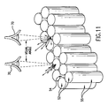
- Light from illumination source 60 is incident on the FOFP 50 at an angle ⁇ with respect to a normal to the plane of the FOFP 50 .
- the light from source 60 is averaged over azimuth, ⁇ , and declination, ⁇ , by the FOFP 50 .
- the light is then reflected from LC material 40 and re-enters the FOFP 50 .
- the light is again averaged over azimuth and declination by FOFP 50 .
- the light that enters the observer's eye 70 has therefore been averaged over azimuth and declination twice and provides effective and symmetric viewing characteristics at all viewing positions. Effective reflectance of the display is no longer restricted to the specular angle.
- the image from the display is much more homogeneous in color and luminance over viewing angle than the same display image without the FOFP 50 .
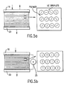
- FIG. 7 shows one embodiment of a FOFP 50 having rounded members 55 , each rounded member 55 comprising optical fibers 52 and transparent cladding material 54 , as shown in FIGS. 10 and 11.
- FIG. 8 shows another embodiment of a FOFP 50 with the surface masked with opaque cladding apertures 56 .
- This may be accomplished by coating the FOFP 50 with a blocking layer that covers only the cladding apertures of the FOFP 50 .
- This coating can be, for example, a metal-metal oxide anti-reflective coating applied over the FOFP 50 and then pattern away over the fiber openings while maintaining the opaque coating on the cladding apertures. The anti-reflective nature of the coating reduces ambient reflections from the FOFP 50 .
- the fiber cores and the cladding materials may be made from chemically different materials.
- the FOFP can then be treated with gas to turn the cladding opaque.
- U.S. Pat. No. 5,442,467 and U.S. application Ser. Nos. 08/473,887 and 08/761,992 discuss the optical properties in greater detail including opaquely marking the cladding apertures.
- FIG. 9 a also shows a Bragg-reflecting non-polarizing LC display according to the present invention.
- Three separate LC cells 90 , 92 and 94 are provided within the display apparatus.
- the first cell 90 includes first substrate 10 and second substrate 10 a .
- the LC material 42 is located between the first and second substrates 10 , 10 a and is reflective of a desired wavelength of light.
- the second LC cell 92 includes third substrate 10 b and fourth substrate 10 c located on opposite sides of the LC material 44 that is reflective of a wavelength of light different than the wavelength corresponding to the LC material 92 of the first cell 90 .
- the third cell 94 includes fifth substrate 10 d and sixth substrate 20 located on opposite sides of the LC material 46 that is reflective of a wavelength of light different than the wavelength corresponding to the LC material 42 and 44 of the first cell 90 and the second cell 92 . As is understandable to one skilled in the art, each of the cells reflects a different wavelength of light.
- the FOFP 50 is located on the side of the first substrate 10 opposite from the LC material 42 . Voltage sources (not shown in FIG. 9) alter the LC material 42 , 44 and 46 and thereby reflect the selective wavelengths as is apparent to one skilled in the art. Intermediate substrates 10 a , 10 b , 10 c and 10 d may be reduced or eliminated to eliminate parallax effects. Furthermore, FOFP 50 may function as the top substrate or containing element of the display as in FIG. 6 a.
- FIG. 9 b shows a further non-polarizing Bragg-reflecting display in which FOFPs 50 a and 50 b are provided between each of the respective LC cells 90 , 92 and 94 .
- FOFPs 50 a and 50 b are provided between each of the respective LC cells 90 , 92 and 94 .
- ITO electrodes are also provided as in other embodiments.
- the FOFP 50 is utilized with any type of non-polarizing Bragg-reflecting display such as described above. Other Bragg-reflecting displays can also use the FOFP 50 of the present invention. This provides several important advantages. First, there is an enhanced reflected luminance at non-specular angles. Second, angular chromaticity shifts resulting from anisotropies in LC configurations and illuminant spectral power distributions are minimized or eliminated. Third, the FOFP minimizes observed inhomogeneities in display texture. As shown in FIGS. 6 a and 6 b , the incident light is funneled through the FOFP 50 , and impinges on the reflecting LC material 40 .
- the light reflected from the material 40 is then transferred back out the FOFP 50 to the observer's eye 70 .
- the light that is incident on the cell is azimuthally averaged before the LC cell and the light reflected by the LC material 40 is again averaged via a second pass through the FOFP 50 .
- the FOFP 50 comprising round members 55 , collects light from all incident angles and azimuthally averages it over angle ⁇ and declination angle ⁇ thereby enhancing reflectance at all non-specular viewing directions and relaying light in a symmetric cone to increase the viewing angle, as shown, for example, in FIGS. 6 a , 6 b and 10 .
- FOFPs also minimize wavelength shifts at wide viewing angles making the shift in color not as noticeable. Also any inhomogeneities in the display texture are removed by the azimuthal averaging effect of the FOFP 50 .
Abstract
Description
Claims (21)
Priority Applications (4)
| Application Number | Priority Date | Filing Date | Title |
|---|---|---|---|
| US08/827,384 US6339463B1 (en) | 1997-03-27 | 1997-03-27 | Enhanced viewing angle performance on non-polarizer based color reflective liquid crystal display using a fiber-optic faceplate |
| EP98301831A EP0867749A3 (en) | 1997-03-27 | 1998-03-12 | Liquid crystal display |
| BRPI9800969-9A BR9800969B1 (en) | 1997-03-27 | 1998-03-25 | liquid crystal screen. |
| JP10082060A JPH10282491A (en) | 1997-03-27 | 1998-03-27 | Liquid crystal display |
Applications Claiming Priority (1)
| Application Number | Priority Date | Filing Date | Title |
|---|---|---|---|
| US08/827,384 US6339463B1 (en) | 1997-03-27 | 1997-03-27 | Enhanced viewing angle performance on non-polarizer based color reflective liquid crystal display using a fiber-optic faceplate |
Publications (1)
| Publication Number | Publication Date |
|---|---|
| US6339463B1 true US6339463B1 (en) | 2002-01-15 |
Family
ID=25249084
Family Applications (1)
| Application Number | Title | Priority Date | Filing Date |
|---|---|---|---|
| US08/827,384 Expired - Lifetime US6339463B1 (en) | 1997-03-27 | 1997-03-27 | Enhanced viewing angle performance on non-polarizer based color reflective liquid crystal display using a fiber-optic faceplate |
Country Status (4)
| Country | Link |
|---|---|
| US (1) | US6339463B1 (en) |
| EP (1) | EP0867749A3 (en) |
| JP (1) | JPH10282491A (en) |
| BR (1) | BR9800969B1 (en) |
Cited By (7)
| Publication number | Priority date | Publication date | Assignee | Title |
|---|---|---|---|---|
| US20020154265A1 (en) * | 2001-04-20 | 2002-10-24 | Hubby Laurence M. | Fiber faceplate suspended particle display |
| US20030146891A1 (en) * | 2000-05-17 | 2003-08-07 | Ran Poliakine | Electronic billboard with reflective color liquid crystal displays |
| US6618104B1 (en) * | 1998-07-28 | 2003-09-09 | Nippon Telegraph And Telephone Corporation | Optical device having reverse mode holographic PDLC and front light guide |
| US6819393B1 (en) | 1998-07-28 | 2004-11-16 | Nippon Telegraph And Telephone Corporation | Optical device and display apparatus using light diffraction and light guide |
| US20060251365A1 (en) * | 2005-05-04 | 2006-11-09 | Brewer Donald R | Watch fiber optic image guide |
| US20060250897A1 (en) * | 2005-05-04 | 2006-11-09 | Brewer Donald R | Analog watch fiber optic image guide |
| US20080223822A1 (en) * | 2005-09-16 | 2008-09-18 | Matsushita Electric Industrial Co., Ltd. | Fiber coating processing and slitting for non-confined light leakage |
Families Citing this family (12)
| Publication number | Priority date | Publication date | Assignee | Title |
|---|---|---|---|---|
| US5942157A (en) | 1996-07-12 | 1999-08-24 | Science Applications International Corporation | Switchable volume hologram materials and devices |
| US6867888B2 (en) | 1996-07-12 | 2005-03-15 | Science Applications International Corporation | Switchable polymer-dispersed liquid crystal optical elements |
| US6821457B1 (en) | 1998-07-29 | 2004-11-23 | Science Applications International Corporation | Electrically switchable polymer-dispersed liquid crystal materials including switchable optical couplers and reconfigurable optical interconnects |
| US6730442B1 (en) | 2000-05-24 | 2004-05-04 | Science Applications International Corporation | System and method for replicating volume holograms |
| US6917399B2 (en) | 2001-02-22 | 2005-07-12 | 3M Innovative Properties Company | Optical bodies containing cholesteric liquid crystal material and methods of manufacture |
| US6573963B2 (en) | 2001-02-22 | 2003-06-03 | 3M Innovativeproperties Company | Cholesteric liquid crystal optical bodies and methods of manufacture |
| US6876427B2 (en) | 2001-09-21 | 2005-04-05 | 3M Innovative Properties Company | Cholesteric liquid crystal optical bodies and methods of manufacture and use |
| FR2849701B1 (en) * | 2003-01-06 | 2005-04-01 | Optogone Sa | DEVICE FOR MONITORING THE POLARIZATION OF A LIGHT SIGNAL USING A POLYMER-STABILIZED LIQUID CRYSTAL MATERIAL |
| US7006747B2 (en) | 2003-01-17 | 2006-02-28 | 3M Innovative Properties Company | Optical devices incorporating photo reactive polymers |
| US6950173B1 (en) | 2003-04-08 | 2005-09-27 | Science Applications International Corporation | Optimizing performance parameters for switchable polymer dispersed liquid crystal optical elements |
| US7813026B2 (en) * | 2004-09-27 | 2010-10-12 | Qualcomm Mems Technologies, Inc. | System and method of reducing color shift in a display |
| US7796234B2 (en) | 2007-04-23 | 2010-09-14 | Sony Ericsson Mobile Communications Ab | Low loss transflective device display comprising a light guide including optical fibers |
Citations (13)
| Publication number | Priority date | Publication date | Assignee | Title |
|---|---|---|---|---|
| US3848965A (en) * | 1973-10-17 | 1974-11-19 | Xerox Corp | Method of controlling monochromatic collimated light by controlling the light reflection band of a liquid crystal |
| US4005929A (en) * | 1975-04-28 | 1977-02-01 | Xerox Corporation | Reflective imaging member |
| US4349817A (en) | 1980-01-28 | 1982-09-14 | Hoffman William C | Liquid crystal display system using fiber optic faceplates |
| US4468137A (en) * | 1980-10-07 | 1984-08-28 | National Research Development Corporation | Temperature indicating devices |
| EP0426291A2 (en) | 1989-10-31 | 1991-05-08 | University Of Hawaii | Colour liquid crystal display |
| US5035490A (en) | 1990-01-09 | 1991-07-30 | Hewlett-Packard Company | Fiber optic |
| US5148297A (en) * | 1990-07-12 | 1992-09-15 | Sharp Kabushiki Kaisha | Liquid crystal display device having an optical fiber substrate including fibers whose periphery is coated with a conductive material |
| US5181130A (en) | 1990-01-09 | 1993-01-19 | Hewlett-Packard Company | Fiber optic faceplate liquid crystal display |
| JPH063691A (en) | 1992-06-24 | 1994-01-14 | Hitachi Ltd | Color liquid crystal display device |
| WO1994010260A1 (en) | 1992-10-30 | 1994-05-11 | Kent State University | Multistable chiral nematic displays |
| US5396351A (en) | 1991-12-20 | 1995-03-07 | Apple Computer, Inc. | Polarizing fiber-optic faceplate of stacked adhered glass elements in a liquid crystal display |
| US5442467A (en) | 1994-03-21 | 1995-08-15 | Xerox Corporation | Enhanced off-axis viewing performance and luminous efficiency of a liquid crystal display employing fiberoptic faceplate elements |
| US5959711A (en) | 1995-06-07 | 1999-09-28 | Xerox Corporation | Enhanced off-axis viewing performance of liquid crystal display employing a fiberoptic faceplate having an opaquely masked front surface on the front face |
-
1997
- 1997-03-27 US US08/827,384 patent/US6339463B1/en not_active Expired - Lifetime
-
1998
- 1998-03-12 EP EP98301831A patent/EP0867749A3/en not_active Ceased
- 1998-03-25 BR BRPI9800969-9A patent/BR9800969B1/en not_active IP Right Cessation
- 1998-03-27 JP JP10082060A patent/JPH10282491A/en active Pending
Patent Citations (14)
| Publication number | Priority date | Publication date | Assignee | Title |
|---|---|---|---|---|
| US3848965A (en) * | 1973-10-17 | 1974-11-19 | Xerox Corp | Method of controlling monochromatic collimated light by controlling the light reflection band of a liquid crystal |
| US4005929A (en) * | 1975-04-28 | 1977-02-01 | Xerox Corporation | Reflective imaging member |
| US4349817A (en) | 1980-01-28 | 1982-09-14 | Hoffman William C | Liquid crystal display system using fiber optic faceplates |
| US4468137A (en) * | 1980-10-07 | 1984-08-28 | National Research Development Corporation | Temperature indicating devices |
| EP0426291A2 (en) | 1989-10-31 | 1991-05-08 | University Of Hawaii | Colour liquid crystal display |
| US5181130A (en) | 1990-01-09 | 1993-01-19 | Hewlett-Packard Company | Fiber optic faceplate liquid crystal display |
| US5035490A (en) | 1990-01-09 | 1991-07-30 | Hewlett-Packard Company | Fiber optic |
| US5148297A (en) * | 1990-07-12 | 1992-09-15 | Sharp Kabushiki Kaisha | Liquid crystal display device having an optical fiber substrate including fibers whose periphery is coated with a conductive material |
| US5396351A (en) | 1991-12-20 | 1995-03-07 | Apple Computer, Inc. | Polarizing fiber-optic faceplate of stacked adhered glass elements in a liquid crystal display |
| US5659378A (en) | 1991-12-20 | 1997-08-19 | Apple Computer, Inc. | Polarizing fiber-optic layer for use with a flat panel display device |
| JPH063691A (en) | 1992-06-24 | 1994-01-14 | Hitachi Ltd | Color liquid crystal display device |
| WO1994010260A1 (en) | 1992-10-30 | 1994-05-11 | Kent State University | Multistable chiral nematic displays |
| US5442467A (en) | 1994-03-21 | 1995-08-15 | Xerox Corporation | Enhanced off-axis viewing performance and luminous efficiency of a liquid crystal display employing fiberoptic faceplate elements |
| US5959711A (en) | 1995-06-07 | 1999-09-28 | Xerox Corporation | Enhanced off-axis viewing performance of liquid crystal display employing a fiberoptic faceplate having an opaquely masked front surface on the front face |
Cited By (11)
| Publication number | Priority date | Publication date | Assignee | Title |
|---|---|---|---|---|
| US6618104B1 (en) * | 1998-07-28 | 2003-09-09 | Nippon Telegraph And Telephone Corporation | Optical device having reverse mode holographic PDLC and front light guide |
| US20040095524A1 (en) * | 1998-07-28 | 2004-05-20 | Nippon Telegraph And Telephone Corporation | Optical device and display apparatus |
| US6819393B1 (en) | 1998-07-28 | 2004-11-16 | Nippon Telegraph And Telephone Corporation | Optical device and display apparatus using light diffraction and light guide |
| US6836314B2 (en) | 1998-07-28 | 2004-12-28 | Nippon Telegraph And Telephone Corporation | Optical device and display apparatus having a plate-shaped light guide and an optical control surface thereon |
| US20030146891A1 (en) * | 2000-05-17 | 2003-08-07 | Ran Poliakine | Electronic billboard with reflective color liquid crystal displays |
| US20020154265A1 (en) * | 2001-04-20 | 2002-10-24 | Hubby Laurence M. | Fiber faceplate suspended particle display |
| US7019810B2 (en) * | 2001-04-20 | 2006-03-28 | Hewlett-Packard Development Company, L.P. | Fiber faceplate suspended particle display |
| US20060251365A1 (en) * | 2005-05-04 | 2006-11-09 | Brewer Donald R | Watch fiber optic image guide |
| US20060250897A1 (en) * | 2005-05-04 | 2006-11-09 | Brewer Donald R | Analog watch fiber optic image guide |
| US20080223822A1 (en) * | 2005-09-16 | 2008-09-18 | Matsushita Electric Industrial Co., Ltd. | Fiber coating processing and slitting for non-confined light leakage |
| US7865049B2 (en) * | 2005-09-16 | 2011-01-04 | Panasonic Corporation | Fiber coating processing and slitting for non-confined light leakage |
Also Published As
| Publication number | Publication date |
|---|---|
| BR9800969A (en) | 1999-10-13 |
| EP0867749A3 (en) | 1999-02-17 |
| BR9800969B1 (en) | 2009-05-05 |
| EP0867749A2 (en) | 1998-09-30 |
| JPH10282491A (en) | 1998-10-23 |
Similar Documents
| Publication | Publication Date | Title |
|---|---|---|
| US6339463B1 (en) | Enhanced viewing angle performance on non-polarizer based color reflective liquid crystal display using a fiber-optic faceplate | |
| US5726723A (en) | Sub-twisted nematic liquid crystal display | |
| EP1664911B1 (en) | Mirror with built-in display | |
| AU2001251596B2 (en) | Polarized display with wide-angle illumination | |
| US6061108A (en) | Broadband cholesteric polarizer and an optical device employing the same | |
| JP4690194B2 (en) | Color LCD with internal rear polarizer | |
| KR100474057B1 (en) | A liquid crystal display device | |
| JP2003177384A (en) | Reflection type liquid crystal display device, manufacturing method therefor and transflective type liquid crystal display device | |
| KR100427881B1 (en) | Half-transmissive liquid crystal display element | |
| AU2001251596A1 (en) | Polarized display with wide-angle illumination | |
| JP3015792B1 (en) | Display element | |
| JP2000075285A (en) | Reflection type liquid crystal display device | |
| JP2000171789A (en) | Display element | |
| KR20040030874A (en) | Reflective liquid-crystal display | |
| US20060098141A1 (en) | High contrast black-and-white chiral nematic displays | |
| JP3289386B2 (en) | Color liquid crystal display | |
| US6674505B1 (en) | Light-modulating cell | |
| US6894743B1 (en) | Liquid crystal optical modulation element, and color filter and liquid crystal display device using the same | |
| JP2005515498A (en) | Combination of cholesteric layer and alignment layer | |
| JP3289392B2 (en) | Color liquid crystal display | |
| KR20030021850A (en) | Liquid crystal display | |
| KR20020058272A (en) | a optical film for liquid crystal display | |
| JPH10186359A (en) | Reflection type liquid crystal display device | |
| JP2003262860A (en) | Liquid crystal display element | |
| JPH10206851A (en) | Reflection type guest-host type liquid crystal display element |
Legal Events
| Date | Code | Title | Description |
|---|---|---|---|
| AS | Assignment |
Owner name: XEROX CORPORATION, CONNECTICUT Free format text: ASSIGNMENT OF ASSIGNORS INTEREST;ASSIGNORS:SILVERSTEIN, LOUIS D.;FISKE, THOMAS G.;CRAWFORD, GREG P.;REEL/FRAME:008493/0697 Effective date: 19970326 |
|
| STCF | Information on status: patent grant |
Free format text: PATENTED CASE |
|
| AS | Assignment |
Owner name: BANK ONE, NA, AS ADMINISTRATIVE AGENT, ILLINOIS Free format text: SECURITY INTEREST;ASSIGNOR:XEROX CORPORATION;REEL/FRAME:013153/0001 Effective date: 20020621 |
|
| AS | Assignment |
Owner name: JPMORGAN CHASE BANK, AS COLLATERAL AGENT, TEXAS Free format text: SECURITY AGREEMENT;ASSIGNOR:XEROX CORPORATION;REEL/FRAME:015134/0476 Effective date: 20030625 Owner name: JPMORGAN CHASE BANK, AS COLLATERAL AGENT,TEXAS Free format text: SECURITY AGREEMENT;ASSIGNOR:XEROX CORPORATION;REEL/FRAME:015134/0476 Effective date: 20030625 |
|
| FPAY | Fee payment |
Year of fee payment: 4 |
|
| AS | Assignment |
Owner name: XEROX CORPORATION, NEW YORK Free format text: RELEASE BY SECURED PARTY;ASSIGNOR:BANK ONE, NA;REEL/FRAME:020540/0850 Effective date: 20030625 Owner name: XEROX CORPORATION, NEW YORK Free format text: RELEASE BY SECURED PARTY;ASSIGNOR:JP MORGAN CHASE BANK, NA;REEL/FRAME:020540/0463 Effective date: 20061204 |
|
| AS | Assignment |
Owner name: XEROX CORPORATION, NEW YORK Free format text: RELEASE BY SECURED PARTY;ASSIGNOR:JP MORGAN CHASE BANK, N.A., SUCCESSOR BY MERGER TO BANK ONE NA;REEL/FRAME:021291/0248 Effective date: 20071129 |
|
| AS | Assignment |
Owner name: THOMSON LICENSING, FRANCE Free format text: ASSIGNMENT OF ASSIGNORS INTEREST;ASSIGNOR:THOMSON LICENSING LLC;REEL/FRAME:022575/0746 Effective date: 20081231 Owner name: THOMSON LICENSING LLC, NEW JERSEY Free format text: ASSIGNMENT OF ASSIGNORS INTEREST;ASSIGNORS:XEROX CORPORATION;PALO ALTO RESEARCH CENTER INCORPORATED;REEL/FRAME:022575/0761;SIGNING DATES FROM 20080804 TO 20080805 |
|
| FPAY | Fee payment |
Year of fee payment: 8 |
|
| FPAY | Fee payment |
Year of fee payment: 12 |
|
| AS | Assignment |
Owner name: XEROX CORPORATION, CONNECTICUT Free format text: RELEASE BY SECURED PARTY;ASSIGNOR:JPMORGAN CHASE BANK, N.A. AS SUCCESSOR-IN-INTEREST ADMINISTRATIVE AGENT AND COLLATERAL AGENT TO JPMORGAN CHASE BANK;REEL/FRAME:066728/0193 Effective date: 20220822 |