EP0436228A2 - Recording and reproducing methods - Google Patents
Recording and reproducing methods Download PDFInfo
- Publication number
- EP0436228A2 EP0436228A2 EP90125700A EP90125700A EP0436228A2 EP 0436228 A2 EP0436228 A2 EP 0436228A2 EP 90125700 A EP90125700 A EP 90125700A EP 90125700 A EP90125700 A EP 90125700A EP 0436228 A2 EP0436228 A2 EP 0436228A2
- Authority
- EP
- European Patent Office
- Prior art keywords
- recording
- light beam
- polarized light
- reproducing
- recording layer
- Prior art date
- Legal status (The legal status is an assumption and is not a legal conclusion. Google has not performed a legal analysis and makes no representation as to the accuracy of the status listed.)
- Granted
Links
Images


Classifications
-
- G—PHYSICS
- G11—INFORMATION STORAGE
- G11B—INFORMATION STORAGE BASED ON RELATIVE MOVEMENT BETWEEN RECORD CARRIER AND TRANSDUCER
- G11B7/00—Recording or reproducing by optical means, e.g. recording using a thermal beam of optical radiation by modifying optical properties or the physical structure, reproducing using an optical beam at lower power by sensing optical properties; Record carriers therefor
- G11B7/004—Recording, reproducing or erasing methods; Read, write or erase circuits therefor
- G11B7/0045—Recording
-
- G—PHYSICS
- G11—INFORMATION STORAGE
- G11B—INFORMATION STORAGE BASED ON RELATIVE MOVEMENT BETWEEN RECORD CARRIER AND TRANSDUCER
- G11B7/00—Recording or reproducing by optical means, e.g. recording using a thermal beam of optical radiation by modifying optical properties or the physical structure, reproducing using an optical beam at lower power by sensing optical properties; Record carriers therefor
- G11B7/24—Record carriers characterised by shape, structure or physical properties, or by the selection of the material
- G11B7/241—Record carriers characterised by shape, structure or physical properties, or by the selection of the material characterised by the selection of the material
- G11B7/242—Record carriers characterised by shape, structure or physical properties, or by the selection of the material characterised by the selection of the material of recording layers
- G11B7/244—Record carriers characterised by shape, structure or physical properties, or by the selection of the material characterised by the selection of the material of recording layers comprising organic materials only
- G11B7/246—Record carriers characterised by shape, structure or physical properties, or by the selection of the material characterised by the selection of the material of recording layers comprising organic materials only containing dyes
- G11B7/247—Record carriers characterised by shape, structure or physical properties, or by the selection of the material characterised by the selection of the material of recording layers comprising organic materials only containing dyes methine or polymethine dyes
- G11B7/2475—Record carriers characterised by shape, structure or physical properties, or by the selection of the material characterised by the selection of the material of recording layers comprising organic materials only containing dyes methine or polymethine dyes merocyanine
-
- G—PHYSICS
- G11—INFORMATION STORAGE
- G11B—INFORMATION STORAGE BASED ON RELATIVE MOVEMENT BETWEEN RECORD CARRIER AND TRANSDUCER
- G11B7/00—Recording or reproducing by optical means, e.g. recording using a thermal beam of optical radiation by modifying optical properties or the physical structure, reproducing using an optical beam at lower power by sensing optical properties; Record carriers therefor
- G11B7/24—Record carriers characterised by shape, structure or physical properties, or by the selection of the material
- G11B7/241—Record carriers characterised by shape, structure or physical properties, or by the selection of the material characterised by the selection of the material
- G11B7/252—Record carriers characterised by shape, structure or physical properties, or by the selection of the material characterised by the selection of the material of layers other than recording layers
- G11B7/253—Record carriers characterised by shape, structure or physical properties, or by the selection of the material characterised by the selection of the material of layers other than recording layers of substrates
- G11B7/2531—Record carriers characterised by shape, structure or physical properties, or by the selection of the material characterised by the selection of the material of layers other than recording layers of substrates comprising glass
-
- G—PHYSICS
- G11—INFORMATION STORAGE
- G11B—INFORMATION STORAGE BASED ON RELATIVE MOVEMENT BETWEEN RECORD CARRIER AND TRANSDUCER
- G11B7/00—Recording or reproducing by optical means, e.g. recording using a thermal beam of optical radiation by modifying optical properties or the physical structure, reproducing using an optical beam at lower power by sensing optical properties; Record carriers therefor
- G11B7/24—Record carriers characterised by shape, structure or physical properties, or by the selection of the material
- G11B7/241—Record carriers characterised by shape, structure or physical properties, or by the selection of the material characterised by the selection of the material
- G11B7/252—Record carriers characterised by shape, structure or physical properties, or by the selection of the material characterised by the selection of the material of layers other than recording layers
- G11B7/258—Record carriers characterised by shape, structure or physical properties, or by the selection of the material characterised by the selection of the material of layers other than recording layers of reflective layers
- G11B7/2585—Record carriers characterised by shape, structure or physical properties, or by the selection of the material characterised by the selection of the material of layers other than recording layers of reflective layers based on aluminium
-
- G—PHYSICS
- G11—INFORMATION STORAGE
- G11B—INFORMATION STORAGE BASED ON RELATIVE MOVEMENT BETWEEN RECORD CARRIER AND TRANSDUCER
- G11B7/00—Recording or reproducing by optical means, e.g. recording using a thermal beam of optical radiation by modifying optical properties or the physical structure, reproducing using an optical beam at lower power by sensing optical properties; Record carriers therefor
- G11B7/24—Record carriers characterised by shape, structure or physical properties, or by the selection of the material
- G11B7/241—Record carriers characterised by shape, structure or physical properties, or by the selection of the material characterised by the selection of the material
- G11B7/252—Record carriers characterised by shape, structure or physical properties, or by the selection of the material characterised by the selection of the material of layers other than recording layers
- G11B7/258—Record carriers characterised by shape, structure or physical properties, or by the selection of the material characterised by the selection of the material of layers other than recording layers of reflective layers
- G11B7/2595—Record carriers characterised by shape, structure or physical properties, or by the selection of the material characterised by the selection of the material of layers other than recording layers of reflective layers based on gold
Definitions
- the present invention relates to recording and reproducing methods and apparatus for an optical recording medium which comprises at least one recording layer containing a photochromic material.
- Such change of molecular structure leads to great change of a light absorption property with respect to the light beam of the prescribed wavelength.
- a photochromic material can be applied to a recording layer for an optical recording medium. Namely, information can be recorded with a recording beam having the aforementioned former wavelength. Then, the information can be reproduced with a reproducing beam having the latter wavelength.
- a photochromic material which is contained in one of the recording layers and adapted to absorb the light beam of the specific wavelength causes photochemical reaction, so that information is recorded in this recording layer.
- the recording layers are irradiated with light beams of corresponding wavelengths respectively, so that data are multiplex-recorded in the recording layers.
- the data thus recorded in the recording layers are read through application of light beams being at intensity levels, for example about 1/10 those in recording.
- a light beam of a certain wavelength may undesirably cause photochemical reaction in a non-correspondent photochromic material, since the photochromic materials spectrally overlap with each other. Consequently, crosstalk is caused when information is recorded/reproduced in the conventional multiplex-wavelength recording method.
- An object of the present invention is, in relation to an optical recording medium employing a photochromic material, to prevent the molecular structure of an already recorded portion from being changed to an unrecorded state upon absorption of a reproducing beam.
- Another object of the present invention is to provide a multiplex recording method employing photochromic materials of the same types and laser beams of the same wavelengths.
- Still another object of the present invention is to prevent crosstalk in a multiplex recording method employing a plurality of photochromic materials.
- a further object of the present invention is to prevent crosstalk from an adjacent recording track.
- a further object of the present invention is to provide an apparatus which can accurately record and/or reproduce information at a high speed in an optical recording medium employing a photochromic material.
- a method for recording information in an optical recording medium comprises a step of preparing an optical recording medium having a recording layer containing a photochromic material, and a step of applying a polarized light beam to the recording layer of the optical recording medium for causing change of optical properties corresponding to its polarized state, thereby recording information.
- a method for reproducing information which is recorded in an optical recording medium comprises a step of preparing an optical recording medium in which information is recorded by causing change of optical properties, a step of applying a reproducing polarized light beam to the recording layer of the optical recording medium, and a step of detecting the reproducing polarized light beam passed through the recording layer, for reproducing information.
- the change of optical properties, which is caused in the recording layer by irradiation with the polarized light beam is introduction of a birefringent property.
- the birefringent property is introduced into the recording layer by application of the polarized light beam, thereby recording information. The information is reproduced by detecting the birefringent property of the recording layer.
- Molecules of a photochromic material which is contained in a recording layer are dispersed in isotropic states when the recording layer is in an unrecorded state.
- photochemical reaction is mainly caused by those of the molecules whose molecular directions are at a specific angle with respect to the plane of polarization of the light beam, to cause change in molecular structure.
- the recording layer has a birefringent property with neutral axes respective to the directions of the molecules.
- a linearly or elliptically polarized light beam is applied to a recording layer to introduce a birefringent property into the recording layer by the aforementioned principle, so that information is recorded in a portion into which the birefringent property is introduced.
- data are read from the recording layer by detecting change of the polarized state of the light beam, which is caused upon passage through the recording layer.
- a polarized light beam for reproducing information has a wavelength in a region of small or no absorption by a photochromic material which is contained in a recording layer.
- the reproducing beam is hardly absorbed in the recording layer. Therefore, it is possible to prevent the molecular structure of the recording layer from being changed to an unrecorded state.
- polarized light beams having different polarized states are employed for multiplex recording of information in a recording layer containing a single photochromic material.
- a photochromic material tends to cause photochemical reaction by a polarized light beam which is in a polarized state corresponding to the direction of its molecular orientation.
- molecules mainly cause photochemical reaction by interaction between the polarized light and transition moment of the molecules having a specific angle.
- large photochemical reaction is caused upon coincidence of the transition moment and the direction of polarization.
- the second aspect of the present invention is adapted to perform multiplex recording of data through such a principle.
- a recording layer of an optical recording medium may contain a photochromic material in a isotropic molecular state.
- photochemical reaction is mainly caused by those of molecules, contained in the photochromic material, which are in directions corresponding to the polarized state of the polarized light beam.
- several types of polarized light beams having different polarized states are applied so that molecules of different directions cause photochemical reaction.
- photochemical reaction is easily caused when the plane of polarization is at a specific angle with respect to the directions of the molecules.
- Such photochemical reaction is hardly caused when the plane of polarization is perpendicular to the specific angle. Namely, the maximum photochemical reaction is caused upon irradiation with a linearly polarized light beam which has a plane of polarization coinciding with transition moment having a specific direction with respect to the directions of the molecules.
- the planes of polarization of the polarized light beams having different polarized states are preferably perpendicular to each other.
- multiplex recording can be performed even if the planes of polarization are not perpendicular to each other.
- the polarized light beams may be elliptically polarized.
- an optical recording medium may have a plurality of recording layers having different directions of molecular orientation.
- the respective recording layers are irradiated with polarized light beams whose polarized states correspond to the directions of molecular orientation in the respective recording layers, to record/reproduce information.
- the directions of molecular orientation of the plurality of recording layers are preferably perpendicular to each other.
- the polarized light beams applied to such a plurality of recording layers have polarized states which correspond to the molecular orientation directions of the respective recording layers.
- the planes of polarization are preferably perpendicular to each other.
- the second aspect it is possible to perform multiplex recording through a single photochromic material with a light beam of a single wavelength.
- an optical recording medium contains a plurality of photochromic materials having different light absorption wavelength regions, and polarized light beams having wavelengths corresponding to the respective photochromic materials are applied to the optical recording medium in different polarized states, to cause optically anisotropic properties in the photochromic materials, thereby multiplex-recording information.
- the third aspect it is possible to prevent crosstalk in multiplex recording through a plurality of photochromic materials having different light absorption wavelength regions.
- the function of the third aspect is now described.
- a recording layer in which information is recorded has direction dependency and wavelength dependency of absorbance.
- a light beam whose wavelength and polarized state correspond to those of a recording beam is applied to detect difference in absorbance thus caused.
- a recording layer of an optical recording medium has a plurality of recording tracks, and polarized light beams of different polarized states are applied to adjacent recording tracks to cause different optically anisotropic properties in the adjacent recording tracks, thereby recording information.
- polarized light beams whose polarized states correspond to directions of the different optically anisotropic properties are applied to the recording tracks, to reproduce the information.
- One of optically anisotropic properties is a birefringent property.
- a polarized light beam is applied to a recording layer causing such a birefringent property, the polarized state of transmitted or reflected light thereof is changed depending on a neutral axis of birefringence.
- Another one of the optically anisotropic properties is angle dependency of absorbance.
- a linearly polarized light beam is applied to a recording layer, for example, there is developed difference in absorbance which depends on an angle formed by planes of polarization of two linearly polarized light beams employed for recording and reproduction, i.e., dichroism. Therefore, it is possible to reproduce information by applying a polarized light beam whose polarized state corresponds to that of a recording beam and detecting change in absorbance.
- neutral axis directions are preferably made different between every adjacent pair of recording tracks.
- the directions of the neutral axes are perpendicular to each other.
- a circularly polarized light beam is applied to a recording layer of an optical recording medium to change optical rotatory power of a photochromic material which is contained in the recording layer, thereby recording information.
- a reproducing polarized light beam is applied to the recording layer, and change of a polarized state which is caused in the reproducing polarized light beam is detected, to reproduce information.
- a certain photochromic material has a property called optical rotatory power, which causes the rotation of the plane of polarization of the light beam.
- optical rotatory power is caused due to difference in refractive index of a medium with respect to lefthanded circular polarization and righthanded circular polarization.
- linear polarization can be interpreted as being formed by superposition of lefthanded circular polarization and righthanded circular polarization of the same phase and amplitude.
- optically active material in a molecular level there is the one having optical isomers which are identical in general chemical property to each other and inverse in optical rotatory power to each other, in mirror-image relation.
- Such an optical isomer has a property called circular dichroism, which develops difference in absorption intensity with respect to lefthanded circular polarization and righthanded circular polarization in an optically active absorption wavelength region having optical rotatory power and absorbing light.
- optical rotatory power and circular dichroism are in close relation to each other.
- absorption intensity ratios with respect to left circular polarization and right circular polarization are inverted in a wavelength region of an optically active absorption band having optical rotatory power and absorbing light.
- information is recorded and reproduced through the aforementioned principle.
- a photochromic material is converted from a state having no optical activity to a state having optical isomerism or vice versa, no optical rotatory power is caused as a whole in a recording layer of a photochromic material containing equal quantities of optical isomers, since optically isomers are inverse in optical rotatory power to each other.
- the information can be reproduced by employing a polarized light beam having a wavelength hardly absorbed by the photochromic material as a reproducing beam, and detecting change of its polarized state.
- information can be non-destructively read by employing a polarized light beam, which is in a wavelength region hardly absorbed by the photochromic material, as a reproducing beam, similarly to the first aspect.
- An apparatus for recording and/or reproducing information comprises polarized state switching means for switching a polarized state of a light beam which is applied to a recording layer.
- This apparatus further comprises a light source for emitting the light beam, and lens means for converging the light beam, whose polarized state is switched, onto the recording layer.
- the polarized state switching means there is an apparatus for mechanically rotating a half-wave plate or a quarter-wave plate for rotating the plane of polarization. In such an apparatus, however, it may be difficult to accurately record and reproduce information at a high speed.
- such polarized state switching means is implemented by electrical means.
- the polarized state switching means comprises an element whose birefringence value is changed by voltage application, and means for applying a voltage to the element.
- the polarized state switching means comprises means for dividing a light beam into two components, means for causing phase difference between the two components of the light beam, and means for re-composing the two components having the phase difference.
- the polarized state can be accurately converted at a high speed since the same is switched by electrical means.
- the recording and/or reproducing apparatus can be accurately increased in operating speed, and reduced in size.
- Fig. 1 shows structures of a spiropyran compound as photochromic material, which can be employed as an exemplary photochromic material contained in a recording layer in the present invention.
- the molecular structure of such a material is converted from a spiropyran form to a merocyanine form upon irradiation with ultraviolet light, and vice versa upon irradiation with visible light, or heating.
- Fig. 2 shows wavelength-to-absorbance characteristics of the material in the respective molecular structures.
- a recording medium is produced by adding a binder of PVB (polyvinyl butyral) to MEK (methyl ethyl ketone) for preparing a solvent, dissolving the aforementioned photochromic material in the solvent and applying this solution onto a substrate of quartz glass by spin coating, thereby forming a recording layer of 1 ⁇ m in thickness.
- PVB polyvinyl butyral
- MEK methyl ethyl ketone
- Fig. 3 shows an optical system of a recording/reproducing apparatus for carrying out a method according to the first aspect of the present invention.
- An ultraviolet light beam emitted from an Ar laser 1 is converted to a pulse beam by a modulator 2.
- components of the beam excluding those of 360 nm in wavelength are eliminated through a filter 3, and the remaining components are expanded to a linearly polarized light beam through a polarizer 4.
- This beam is converted to an uniform beam by a beam expander 5, and thereafter introduced into an objective lens 8 through a dichroic mirror 6 and a Faraday rotator 7, to be converged on a recording layer 10 of a medium 9.
- code tracks are formed on the recording layer 10 as a train of birefringent portions (recorded portions).
- a semiconductor laser 11 emits a linearly polarized light beam of 780 nm in wavelength.
- This beam is converted to a collimated beam through a collimator lens 12, and then converged on the recording layer 10 of the medium 9 through the Faraday rotator 7 and the objective lens 8.
- a control circuit 13 drives/controls the Faraday rotator 7 to introduce the beam into the recording layer 10 so that its plane of polarization is at an angle of 45° with respect to that of the aforementioned beam which is emitted from the Ar laser 1.
- Neutral axes of birefringence of the recorded portions, which are formed on the recording layer 10 by the Ar laser 1 are formed in inclination by prescribed angles with respect to the plane of polarization of the Ar laser 1.
- the linearly polarized light beam which is emitted from the semiconductor laser 11, is applied to the recorded portions of the recording layer 10 so that its plane of polarization is at an angle of 45° with respect to the neutral axes.
- a linearly polarized light beam When a linearly polarized light beam is so introduced into a birefringent material that its plane of polarization is inclined with respect to a neutral axis, the beam is converted to an elliptically polarized light or circularly polarized light beam upon transmission through the material.
- a birefringent material is adapted to change the phases of beam components which are parallel to the neutral axis, such as a fast axis, for example, with respect to those of components which are perpendicular to the neutral axis.
- the principle of the aforementioned conversion of the linearly polarized light beam to the elliptically polarized light beam is based on such a property.
- the linearly polarized light beam emitted from the semiconductor laser 11 is applied onto the recorded portions of the recording layer 10 so that its plane of polarization is at the angle of 45° with respect to the neutral axes, whereby the polarized state of the light beam is converted from linear polarization to elliptic polarization or circular polarization upon transmission through the recording layer 10.
- the plane of polarization of the linearly polarized light beam is thus set at the angle of 45° with respect to the neutral axes, the aforementioned parallel components of the linearly polarized light beam with respect to the neutral axes are equal to the perpendicular components, whereby it is possible to maximize the aforementioned change of the polarized state.
- the beam thus transmitted through the recording layer 10 is introduced into a polarizing beam splitter 15 through the lens 14, so that transmitted and reflected beams are received by sensors 16 and 17 respectively.
- the polarizing beam splitter 15 is so arranged as to fully transmit the linearly polarized light beam from the semiconductor laser 11 when no medium 9 is provided.
- no change is caused in the polarized state of the light beam upon transmission through the medium 9. Therefore, the light beam is fully transmitted through the polarizing beam splitter 15 to cause an output only at the sensor 16.
- the beam is converted to an elliptically polarized light beam upon transmission through the medium 9, as hereinabove described. Therefore, the beam is partially reflected by the polarizing beam splitter 15, to cause outputs at both of the sensors 16 and 17 in this case.
- the sensors 16 and 17 when the medium 9 is relatively moved and the objective lens 8 is displaced to scan the aforementioned tracks of the recording layer 10 with the light beam which is emitted from the semiconductor laser 11, the sensors 16 and 17 generate outputs in response to the data recorded on the tracks, whereby the data can be changed to electrical signals by comparing the outputs of the sensors 16 and 17.
- the optical system according to this embodiment and the medium described above were employed to experimentally record and reproduce data, whereby it was possible to confirm changes in response to recorded and unrecorded states in the outputs from the sensors 16 and 17.
- the Ar laser 1 and the semiconductor laser 11 were set at 6 mW and 0.5 mW in laser power respectively.
- the beam emitted from the Ar laser 1 was pulsingly applied to the medium 9 by 10 ⁇ sec. to form a spot-type recorded portion on the recording layer 10, while the beam emitted from the semiconductor laser 11 was applied to this recorded portion and the remaining unrecorded portion, to compare outputs of the sensors 16 and 17 with each other.
- the Faraday rotator 7 and a beam scanning mechanism (not shown) while selectively driving the Ar laser 1 and the semiconductor laser 11 in response to recording and reproduction.
- the beam emitted from the semiconductor laser 11 employed for reproduction has the wavelength of 780 nm, which is not in the least absorbed by the photochromic material contained in the recording layer 10, as understood from the characteristic diagram shown in Fig. 2.
- the reproducing beam will not act on the photochromic material to change its molecular structure, and hence no undesirable change is caused in the recording layer 10 in reproduction of data with the reproducing beam.
- the first aspect of the present invention is not restricted to the aforementioned embodiment, but various modifications are also available.
- the Faraday rotator 7 and the control circuit 13 are adapted to incline the plane of polarization of the beam emitted from the semiconductor laser 11 with respect to the neutral axes of the recorded portions on the recording layer 10 in the aforementioned embodiment
- arrangement of the semiconductor laser 11 may be adjusted by rotating the same about its optical axis of emission in place of arranging the Faraday rotator 7 and the control circuit 13, so as to incline the plane of polarization of the laser beam with respect to the neutral axes on the recording layer 10.
- a circularly polarized light beam may alternatively be employed for reproduction.
- Fig. 4 shows an optical system for such a modification. This modification is different from the embodiment shown in Fig. 3 in a point that two quarter-wave plates 18 and 19 are arranged in place of the Faraday rotator 7 and the control circuit 13. In a recording operation, the quarter-wave plate 18 is shifted toward the exterior of an optical path of a beam.
- a linearly polarized light beam which is emitted from a semiconductor laser 11, is converted to a circularly polarized light beam through the quarter-wave plate 18, and thereafter introduced into a recording layer 10 of a medium 9.
- the beam is introduced in an unrecorded portion of the recording layer 10, no change is caused in the polarized state of the beam upon transmission through the recording layer 10.
- the beam is transmitted through the medium 9 in the circularly polarized state, and introduced into the quarter-wave plate 19 and again converted to a linearly polarized light beam.
- a polarized beam splitter 15 is previously position-controlled to fully transmit the beam thus converted to the linearly polarized state.
- the beam When the beam is introduced into a recorded portion of the recording layer 10, on the other hand, its polarized state is converted from circular polarization to elliptic polarization upon transmission through the recorded portion having a birefringent property. Therefore, the beam is not converted to a linearly polarized state upon passage through the quarter-wave plate 19. Thus, the beam which is transmitted through the recorded portion of the recording layer 10 is partially reflected by the polarizing beam splitter 15, to develop an output also at another sensor 17.
- the medium is formed by a transmission type one in the aforementioned embodiment, a reflection type medium can alternatively be employed in order to achieve recording/reproducing operation similarly to the above, by slightly modifying the optical system in a proper manner.
- the photochromic material, the wavelengths of the laser beams and the like can also be modified in various ways, as a matter of course.
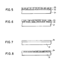
- Fig. 5 is a sectional view showing a medium according to a first embodiment of the second aspect of the present invention.
- first and second recording layers 22 and 23 are successively formed on a transparent substrate 21.
- the first and second recording layers 22 and 23 contain the same organic photochromic materials, whose molecular orientation directions are perpendicular to each other.
- the molecular orientation direction of the first recording layer 22 is perpendicular to the plane of the figure, while that of the second recording layer 23 is parallel to the plane of the figure. Therefore, planes of polarization of beams causing significant reaction in molecules contained in the respective recording layers are perpendicular to each other in relation to directions of transition moment responsive to the molecular orientation directions of the respective layers.
- Fig. 6 is a sectional view showing the medium in which data are recorded. Referring to Fig. 6, recorded portions are shown with slant lines.
- the recording layers 22 and 23 are formed by the LB technique (Langmuir-Blodgett's technique) or the like.
- Fig. 7 shows the structure of a medium according to a second embodiment of the second aspect of the present invention.
- This embodiment comprises a single recording layer 24, which contains a photochromic material in a non-oriented state with no regular molecular orientation.
- photochemical reaction is mainly caused by those of the molecules forming the photochromic material which are oriented in a direction responsive to the plane of polarization of the linearly polarized light beam, i.e., molecules having transition moment coinciding with the plane of polarization.
- Fig. 8 is a side sectional view showing the medium in which such data are recorded. Referring to Fig. 8, recorded portions are shown with slant lines.
- a medium having the structure of the first embodiment was produced in practice, to make an experiment with respect to recording/reproduction. This experiment is now described.
- a substrate material was prepared from quartz, and a photochromic material contained in recording layers was prepared from the spiropyran compound shown in Fig. 1.
- a photochromic material is changed from the spiropyran form to a merocyanine form upon irradiation with ultraviolet light, and vice versa upon irradiation with visible light, or heating.
- a film containing this photochromic material is provided on a substrate 21 by the LB technique to form a first recording layer 22, and then another film is provided on the first recording layer 22 by the same material and the same technique, to form a second recording layer 23.
- the films are formed by the LB technique so that the molecular orientation directions in these films are perpendicular to each other.
- Both of the linearly polarized light beams are emitted from an Ar laser, at wavelengths of 360 nm.
- Fig. 9 shows an optical system for applying such beams.
- the beams are emitted from an Ar laser 31, and converted to pulsing beams through an A-O(acoustoopic modulator) 32.
- the beams are adjusted to be linearly polarized light beams of 360 nm in wavelength through a filter 33 and a linear polarizer 34.
- the adjusted beams are expanded by a beam expander 35, then transmitted through a dichroic mirror 36, and introduced into a Faraday rotator 37.
- the Faraday rotator 37 is controlled by a control unit (not shown), to rotate the planes of polarization of the linearly polarized light beams.
- the beams passed through the Faraday rotator 37 are converged onto the recording layers 22 and 23 of a medium M through an objective lens 38, to record data in the recording layers 22 and 23.
- the recorded data are erased with a visible light beam of 633 nm in wavelength which is emitted from an He-Ne laser 39.
- a filter 40 and a linear polarizer 41 function similarly to the aforementioned filter 33 and linear polarizer 34.
- the erasing beam is expanded by a beam expander 44, reflected by a dichroic mirror 46, and thereafter converged on the medium M.
- a convergent lens 43 and a photoelectric converter 44 defines a photoreceptor part for receiving the beam transmitted through the medium M.
- an Ar laser beam is applied to the medium M at a specific angle with respect to the molecular orientation direction of the first recording layer 22, so that its plane of polarization is identical to the direction of transition moment.
- the irradiation power and irradiation time of this beam are 4 mw and 5 ⁇ sec. respectively.
- the irradiation time is adjusted by controlling the A-O modulator 32.
- Ar laser beam is applied at lower irradiation power I e of 0.2 mw so that the photochromic materials cause almost no reaction, to measure absorbance of the medium M.
- the absorbance can be evaluated by calculating log10 , assuming that I e represents the irradiation power of the beam and I represents the transmission power.
- the transmission power I is obtained by measuring the output of the photoelectric converter 44. Several levels of such absorbance are measured on the basis of an angle ⁇ of rotatory polarization of the beam with reference to the direction of the plane of polarization at the specific angle, i.e., transition moment of the molecule, of the first recording layer 22. The angle ⁇ of rotatory polarization of the beam is adjusted by controlling the Faraday rotator 37.
- the irradiation power and irradiation time of the beam are 4 nm and 5 ⁇ sec. respectively, similarly to the above.
- absorbance is measured in a similar manner to the above.
- absorbance of a non-irradiated portion of the medium is measured in a similar manner to the above.
- Fig. 10 shows the results of measurement of absorbance in relation to the aforementioned experiment.
- the medium shown in Fig. 7 was manufactured in practice, and an experiment similar to the above was made to measure absorbance characteristics.
- the medium was produced by dissolving the spiropyran compound shown in Fig. 1 in a solvent and applying the solution onto an upper surface of a substrate made of quartz glass similarly to the above, thereby forming a recording layer of 1 ⁇ m in thickness.
- the photochromic material was in a non-oriented state since the same was simply applied for forming the recording layer.
- Two types of beams, whose planes of polarization were perpendicular to each other, were applied to this medium similarly to the above for recording data in the recording layer. Thereafter absorbance characteristics were measured similarly to the above, whereby results similar to those of the aforementioned experiment were obtained.
- the irradiation power of the recording laser beam was slightly increased to 6 mw, as compared with 4 mw in the above experiment. This is because reaction sensitivity of the non-oriented photochromic material was reduced as compared with the aforementioned oriented photochromic material.
- the medium is preferably brought into the state shown in Fig. 5.
- the medium must be provided with two recording layers through a specific method such as the LB technique.
- the medium is preferably brought into the structure shown in Fig. 7.
- elliptic polarization may be employed in place of linear polarization.
- the third aspect according to the present invention utilizes the following principle:
- a recording layer made of a non-oriented photochromic material difference in absorbance is caused between a recorded state irradiated with a linearly polarized light beam for recording and a non-irradiated unrecorded state, as shown in Fig. 11.
- Fig. 11 While the output is reduced when data are reproduced with a linearly polarized light beam of a direction different from an unrecorded track and the said specific direction by 90°.
- the relation shown in Fig. 11 may be varied with the photochromic material and the wavelength of the recording or reproducing beam.
- the optically anisotropic direction is generally defined as a direction causing significant difference in absorbance between the recording and reproducing beams as employed.
- information is recorded by irradiating a recording medium, which contains a plurality of types of photochromic materials, with a linearly polarized light beam having a wavelength in a light absorption wavelength region of the photochromic materials and being linearly polarized in a specific direction.
- a recording layer contains a photochromic material X which has light absorption at a wavelength ⁇ x (absorption maximum wavelength, in general) and another photochromic material Y which has light absorption at a wavelength ⁇ y (absorption maximum wavelength, in general), for example, absorbance curves of a randomly or linearly polarized feeble light beams in an unrecorded state are as shown by solid lines in Figs. 12A to 12C.
- the recording layer can contain fulgide, diallyl ethene and/or spiropyran compound as photochromic materials.
- Figs. 13A and 13B illustrate two types of exemplary spiropyran photochromic materials A and B.
- the molecular structures of the photochromic materials A and B are converted from spiropyran forms to photomerocyanine forms upon irradiation with ultraviolet light, and vice versa upon irradiation with visible light.
- the photochromic material A is irradiated with light around an absorption maximum wavelength of 620 nm and the material B is irradiated with light around an absorption maximum wavelength of 470 nm, so that the molecular structures thereof return from the photomerocyanine forms to the spiropyran forms.
- absorbance levels at the respective absorption maximum wavelengths are reduced.
- the two types of photochromic materials A and B were mixed with each other and applied onto quartz substrates by spin coating, to produce recording mediums which were provided with recording layers. These recording mediums contained the photochromic materials in isotropic states, with no molecular orientation. Data were experimentally recorded/reproduced in/from the recording mediums by a conventional method and the inventive method respectively.
- curves a illustrate absorbance values of recording mediums which are colored by irradiation with randomly polarized ultraviolet light (unrecorded states)
- curves b illustrate absorbance values measured after applying linearly polarized light beams of a wavelength 470 nm to colored (unrecorded) mediums for recording data
- curves c illustrate absorbance values measured after simultaneously applying two linearly polarized light beams of 470 nm and 620 nm in wavelength, which are identically polarized in directions perpendicular to each other, to colored recording mediums for recording data.
- the present invention is also applicable to a recording medium which contains three or more photochromic materials.
- Figs. 16A to 16C show absorbance characteristics of three types of photochromic materials a , b and c .
- the photochromic materials a , b and c in a recording medium are dispersed in non-oriented states.
- Fig. 16A shows absorbance of the material a
- Fig. 16B shows absorbance of the material b
- Fig. 16C shows absorbance of the material c .
- Fig. 16D shows absorbance of a medium which is prepared by stacking or mixing the materials a , b and c .
- information may be recorded/reproduced with light beams having wavelengths ⁇ a and ⁇ c which are linearly polarized in the same direction and a light beam having a wavelength ⁇ b which is linearly polarized in a direction perpendicular to the aforementioned direction. It is possible to prevent crosstalk between the wavelengths ⁇ a and ⁇ b as well as between the wavelengths ⁇ b and ⁇ c by an effect similar to that in the aforementioned case of employing two types of photochromic materials.
- the crosstalk of the wavelengths of ⁇ a and ⁇ c is sufficiently small since absorption lines of the wavelengths ⁇ a and ⁇ c hardly overlap with each other. Thus, information can be recorded/reproduced substantially with no crosstalk.
- a recording layer for a recording medium is formed by mixing two types of photochromic materials A and B and applying the same onto a transparent substrate.
- the photochromic materials A and B in a recording layer are dispersed in non-oriented states.
- Information is recorded by applying a linearly polarized light beam having a wavelength ⁇ A , which is absorbed by the material A, and another linearly polarized light beam having a wavelength ⁇ B , which is absorbed by the material B. These beams are so applied that directions of linear polarization thereof are perpendicular to each other on the same portions of the recording layer and the directions of linear polarization at the respective wavelengths are perpendicular every adjacent pair of tracks.
- Fig. 17 shows directions of linear polarization of the light beams of the respective wavelengths ⁇ A and ⁇ B on tracks 50a, 50b and 50c.
- solid arrows show the directions of polarization of the wavelength ⁇ A and dotted lines show those of the wavelength ⁇ B .
- linear polarized light beams having the same wavelengths as those of the recording beams and corresponding to the directions of polarization of the wavelengths in recording.
- the second embodiment as hereinabove described, it is possible to prevent crosstalk based on light beams having different wavelengths. Further, the directions of linear polarization of the light beams having different absorption wavelengths are perpendicularly crossed every adjacent pair of tracks, whereby it is possible to reduce outputs related to adjacent tracks, as well as to prevent crosstalk from adjacent tracks.
- each of the first and second embodiments has been described, with reference to a recording medium containing a plurality of photochromic materials in a single recording layer, it is also possible to reduce crosstalk in a laminated type recording medium which is prepared by stacking a plurality of recording layers made of photochromic materials having different absorption wavelength regions. Further, a similar effect is also attained in a laminated type recording medium which is prepared by stacking a plurality of recording layers each formed of a plurality of photochromic materials having different absorption wavelength regions.
- a first light source 71, a second light source 81 and a third light source 91 output linearly polarized light beams of the wavelengths ⁇ a , ⁇ b and ⁇ c , which are absorbed by the aforementioned three types of photochromic materials, respectively.
- the linearly polarized light beam of the wavelength ⁇ a outputted from the first light source 71 is converted to a parallel light beam through a lens 72 in the linearly polarized state, and thereafter passed through an isolator 73, which is formed by combination of a Faraday rotator, a polarizer, and the like, for preventing noise caused by return of reflected light to the first light source 71.
- the parallel light beam is transmitted through a half mirror 74 in a state of P-polarized light or S-polarized light, passed through dichroic mirrors 56 and 57, and converged on the recording layer 63 of the recording medium 61 through an objective lens 52, to record information.
- the linearly polarized light beam of the wavelength ⁇ b outputted from the second light source 81 is converted to a parallel light beam through a lens 82 in the linearly polarized state, and then passed through an isolator 83 and a half mirror 84.
- the passed parallel light beam is reflected by the dichroic mirror 56, which has high reflectance for the beam of the wavelength ⁇ b , and then passed through the dichroic mirror 57.
- the passed collimated beam is converged on the recording layer 63 through the objective lens 52, to record information.
- the linearly polarized light beam of the wavelength ⁇ c outputted from the third light source 91 is converted to a parallel light beam through a lens 92 in the linearly polarized state, and then passed through an isolator 93 and a half mirror 94.
- the passed parallel light beam is reflected by the dichroic mirror 57, which has high reflectance for the beam of the wavelength ⁇ c , and thereafter converged on the recording layer 63 through the objective lens 52, to record information.
- This optical system is so adjusted that the linearly polarized light beams of the wavelengths ⁇ a and ⁇ c are polarized in the same direction and the light beam of the wavelength ⁇ b is perpendicularly polarized with respect to the said light beams.
- a half-wave plate or the like may be appropriately employed in order to attain such adjustment.
- the outputs of the respective light sources are generally reduced and linearly polarized light beams of the respective wavelengths are applied to the recording layer in response to the directions of linear polarization of the recording beams of the respective wavelengths (generally the same directions), to detect the as-formed reflected light beams with sensors corresponding to the respective wavelengths.
- the linearly polarized light beam of the wavelength ⁇ a outputted from the first light source 71 is passed through the lens 72, the isolator 73, the half mirror 74 and the dichroic mirrors 56 and 57, and thereafter converged on the recording layer 63 through the objective lens 52.
- the direction of linear polarization of the light beam having the wavelength ⁇ a generally coincides with that of the recording beam of the wavelength ⁇ a .
- the linearly polarized light beam converged on the recording layer 63 is transmitted therethrough and reflected by the reflective layer 62, so that the reflected light beam is emitted from the recording medium 51.
- This reflected light beam is passed through the dichroic mirrors 57 and 56, reflected by the half mirror 74, and passed through a filter 75, which is mainly adapted to pass only the light beam of the wavelength ⁇ a . Thereafter the beam is converged on/detected by a sensor 76 through a lens 77, to reproduce information.
- the linearly polarized light beam of the wavelength ⁇ b emitted from the second light source 81 similarly forms a reflected light beam through the recording medium 51.
- the reflected light beam is transmitted through the objective lens 52 and the dichroic mirror 57, and thereafter reflected by the dichroic mirror 56, which has high reflectance for the beam of the wavelength ⁇ b .
- this beam is reflected by the half mirror 84, and transmitted through a filter 85, which is mainly adapted to transmit only the beam of the wavelength ⁇ b .
- the transmitted reflected beam is converged on a sensor 86 through a lens 87, to reproduce the information.
- the linearly polarized light beam of the wavelength ⁇ c emitted from the third light source 91 also forms a reflected beam through the recording medium 51.
- This reflected beam is reflected by the dichroic mirror 57, which has high reflectance for the beam of the wavelength ⁇ c , then reflected by the half mirror 94, and transmitted through a filter 95, which is mainly adapted to transmit only the beam of the wavelength ⁇ c .
- the transmitted reflected beam is converged on a sensor 96 through a lens 97, to reproduce the information.
- the light sources are generally formed by gas lasers such as He-Ne lasers and Ar lasers, semiconductor lasers, or the like. If the gas lasers are employed, the light sources are provided with A-O modulators etc. for modulating outputted beams.
- the optical systems corresponding to the respective wavelengths may be arranged in the same optical head, while a plurality of optical heads may alternatively be provided in response to the respective wavelengths. Although a single optical system has been illustrated with respect to a reflection type recording medium in the above description, the recording medium may alternatively have another structure. Further, a transmission type recording medium can also be easily implemented through a similar principle.
- the aforementioned recording medium contains three types of photochromic materials
- a recording layer containing at least two types of photochromic materials is also available in a similar optical system. While information is recorded/reproduced with linearly polarized light beams in each of the first to third embodiments, a similar effect can be attained with beams of other polarized states, such as elliptically polarized light beams.
- the directions of linear polarization and elliptic polarization are not restricted to those of the aforementioned embodiments. For example, although the directions of linear polarization are at an angle of 90° (perpendicular) in the first embodiment, such an angle may differ from 90°, so far as the effect of preventing crosstalk is maintained.
- Fig. 19 illustrates an optical system of a recording/reproducing apparatus of a first embodiment according to the fourth aspect of the present invention.
- a recording medium 120 is produced by adding a binder of PVB (polyvinyl butyral) to MEK (methyl ethyl ketone) for preparing a solvent, dissolving a photochromic material in this solvent, applying the solution onto a transparent substrate 121 of glass, quartz or resin by spin coating for forming a recording layer 123 of 1 ⁇ m in thickness, and forming a reflective layer 122 of Al or the like on the recording layer 123.
- PVB polyvinyl butyral
- MEK methyl ethyl ketone
- the recording layer 123 contains the photochromic material in a non-oriented state with no molecular orientation.
- this medium 120 is irradiated with a linearly polarized light beam having a wavelength absorbed by the photochromic material, there is a high probability that those of molecules of the photochromic material having specific direction in response to the plane of polarization of the linearly polarized light beam cause photochemical reaction. Therefore, the aforementioned linearly polarized light beam is adapted to scan the recording layer 123, to form recorded portions having optically anisotropic directions which are responsive to the plane of polarization of the linearly polarized light beam.
- This beam is converted to a pulse beam through a modulator 102, which is adapted to modulate the intensity of the recording incident beam in response to an information signal, and then introduced into a half-wave plate 108 for changing the direction of the plane of linear polarization (direction of polarization) of the recording incident beam.
- the half-wave plate 108 rotates the direction of its neutral axis, to change the direction of linear polarization of the recording incident beam.
- the beam is introduced into an objective lens 103 through a dichroic mirror 104, and converged in the recording layer 123 of the recording medium 120 through the objective lens 103.
- the recording medium 120 is relatively moved in a prescribed direction to modulate the recording incident beam through the modulator 102 in response to information, thereby forming recording tracks, which have optically anisotropic directions in response to the plane of linear polarization of the recording incident beam, on the recording layer 123.
- those coincident in transition moment with the direction of linear polarization of the recording incident beam mainly cause photochemical reaction, to form the recording tracks.
- the direction of the plane of polarization of the half-wave plate 108 is so rotated as to perpendicularly cross the direction of linear polarization of the recording incident beam, which is converged on the recording layer 123, every pair of adjacent tracks.
- the as-formed recording tracks have optically anisotropic directions in response to the plane of polarization of the linearly polarized recording light beam, as shown by slant lines in Fig. 22.
- the optically anisotropic directions of adjacent recording tracks A, B and C are perpendicular to each other.
- the intensity of the reproducing beam emitted from the second light source 106 is set at a sufficiently small level so that the recording layer 123 causes no reaction with the beam, which is linearly polarized.
- the beam is passed through a beam splitter 105, and introduced into a half-wave plate 109.
- the half-wave plate 109 is so rotated that the optically anisotropic direction of every recording track coincides with the plane of polarization of the linearly polarized light beam.
- the beam is applied to the recording layer 123 of the recording medium 120 through the dichroic mirror 104 and the objective lens 103. Then the beam is reflected by the reflective layer 122 while maintaining its polarized state. The reflected beam is received by a sensor 107 through the objective lens 103, the dichroic mirror 104, the half-wave plate 109, the beam splitter 105, and a lens 111. Thus, the sensor 107 outputs an electric signal which is modulated in response to information held in each recording track.
- data such as track address numbers are preformatted in the recording medium 120, for example. Rotation of the half-wave plate 109 is controlled on the basis of the detected track address numbers.
- the second light source 106 emits a feeble light beam of a constant output, which is applied to the recording layer 123 of the recording medium 120 through the beam splitter 105, the dichroic mirror 104 and the objective lens 108. Thereafter a reflected light beam resulting from such application of the feeble light beam is detected by the sensor 107 through the objective lens 103, the dichroic mirror 104, the half-wave plate 109, the beam splitter 105 and the lens 111, to carry out focus servo operation and tracking servo operation etc.
- the light beams emitted from the first and second light sources 101 and 106 are adjusted by the dichroic mirror 104, so that the optical axes thereof coincide with each other.
- the present invention is not restricted to this embodiment, but is also applicable to a disk unit having spiral tracks, for example.
- a structure can be easily implemented by providing the aforementioned unit with a circuit which is connected with a polarization plane rotating/driving unit (not shown) for detecting synchronizing signals from a rotating/driving system of the recording medium 120 and rotating neutral axes of the half-wave plates 108 and 109, thereby rotating planes of polarization of linearly polarized light beams and continuously rotating the plane of polarization of a linearly polarized light beam which is introduced into the recording medium 120 in synchronization with the rotation of the aforementioned rotating/driving system, so as to perpendicularly cross the plane of polarization of the linearly polarized light beam introduced into adjacent tracks.
- the structure may be set to rotate the plane of polarization of the linearly polarized light beam by 90° every
- Fig. 23 is a conceptual diagram showing recording tracks which are formed on a recording medium in the aforementioned manner by a dotted line, and optically anisotropic directions thereof by arrows. It is assumed here that a half-wave plate reproduces information in an asynchronous state with respect to a disk in an initial stage of reproduction, and is synchronized with rotation of the disk when the reproducing output is maximized.
- the recording medium may or may not be provided with grooves, guard bands, or the like.
- the optically anisotropic direction of a recording track storing the information to be reproduced is rendered coincident with the plane of linear polarization of the aforementioned reproducing beam, to attain a sufficient reproducing output. Even if the reproducing beam is partially applied to an adjacent recording track, substantially no output is generated in relation to the adjacent track since the optically anisotropic direction of the main recording track is perpendicular to the plane of polarization of the reproducing beam. Thus, it is possible to reduce crosstalk caused by the adjacent recording track in reproduction of the main recording track.
- Fig. 24 illustrates an optical system for reproducing information from a recording/reproducing apparatus according to the second embodiment. Parts identical to those of the first embodiment are denoted by the same reference numerals, to omit redundant description.
- information is reproduced with a randomly or circularly polarized light beam, in place of the linearly polarized light beam employed in the first embodiment.
- a randomly polarized light beam emitted from a second light source 106, such as an He-Ne laser, of a wavelength ⁇ of 633 nm or a circularly polarized light beam generated through a half-wave plate (not shown) is transmitted through a beam splitter 105.
- the beam splitter 105 has equal reflectance and transmittance with respect to P-polarized light and S-polarized light.
- the light beam passed through the beam splitter 105 is converged on a recording layer 123 of a recording medium 120 through a dichroic mirror 104 by an objective lens 103, to form a reflected light beam.
- a reflected light beam When the randomly or circularly polarized light beam is converged on the recording tracks shown in Fig. 21, for example, those of polarized components of the as-formed reflected light beam coinciding with the optically anisotropic directions (defined as directions causing large difference in absorbance) are mainly modulated by information recorded in the tracks, while those perpendicular to the optically anisotropic directions of the recording tracks are hardly modulated.
- the reflected light beam is reflected by the beam splitter 105 through the dichroic mirror 104.
- the beam reflected by the beam splitter 105 is introduced into a polarizing beam splitter 104, and branched into a beam of modulated polarized components and that of unmodulated polarized components.
- the polarized components of the branched reflected light beam are detected by a sensor 151 or 152 through a lens 131 or 132 in response to P-polarized light or S-polarized light, to reproduce information.
- a method of determining a larger output as the signal reproduced from the main recording track through the fact that the signal reproduced form the main recording track is generally larger than a reproduced output related to crosstalk In order to identify the one of the sensors 151 and 152 which receives the reproducing signal from the main recording track, there is a method of determining a larger output as the signal reproduced from the main recording track through the fact that the signal reproduced form the main recording track is generally larger than a reproduced output related to crosstalk.
- data such as track positions (address numbers), polarized states or the like are preformatted in production of the disk, and read in reproduction to select the signal which is reproduced from the main recording track.
- the track position is detected by a track position detecting sensor (not shown), to select the signal reproduced from the main recording track.
- information recorded in a recording track formed with a polarized light beam which is perpendicular to that for an adjacent track is reproduced with such a randomly or circularly polarized light beam that only polarized components along the optically anisotropic direction of the recording track are modulated.
- the modulated polarized components related to the main and adjacent recording tracks are perpendicularly crossed. Consequently, the reproducing output related to the main recording track can be separated from that related to the adjacent track, thereby reducing crosstalk caused by the adjacent recording track.
- two light sources may alternatively be employed to emit linearly polarized light beams.
- the reproducing light beam which is absorbed by the photochromic material contained in the recording layer 123 even if its intensity is set at a small value, may change the molecular structure of the photochromic material, to cause undesirable change in the recording layer 123.
- a third embodiment according to the fourth aspect of the present invention can eliminate such inconvenience.
- the third embodiment is adapted to record and reproduce information through birefringence, which is one of optical anisotropic properties, caused by irradiating the recording layer 123 with a linearly polarized light beam.
- Fig. 25 schematically illustrates a reproducing optical system which is included in a recording/reproducing apparatus according to the third embodiment.
- information is recorded in a recording layer 123 of a recording medium 120 through a recording optical system (not shown) which is similar to that of the first embodiment.
- recording tracks such as those shown in Fig. 22 are formed so that optical anisotropic directions (shown by slant lines) of adjacent recording tracks are perpendicular to each other, as a train of portions (recorded portions) having birefringence.
- the optically anisotropic directions of the recording tracks are defined as directions of neutral axes of birefringence (i.e., fast axes or slow axes) caused in coincidence with the direction of polarization (plane of polarization) of a linearly polarized light beam for recording.
- a light beam of a wavelength which is hardly or not in the least absorbed by the recording layer 123 of the recording medium 120 is applied, to detect presence/absence of birefringence of the recording layer 123 by a transmitted or reflected light beam thereof.
- a linearly polarized incident light beam outputted from the third light source 170 is reflected by a half mirror 160.
- the half mirror 160 has equal transmittance and reflectance with respect to P-polarized light and S-polarized light.
- the incident light beam introduced into the half mirror 160 is preferably set to be in the state of P-polarized light or S-polarized light, so that the same is not applied to the recording layer 123 in an elliptically polarized state due to phase difference caused upon reflection by the half mirror 160.
- the beam reflected by the half mirror 160 is applied to the recording layer 123 of the recording medium 120 through an objective lens 171.
- the plane of linear polarization, shown by slant lines, of the beam which is applied to the recording medium 120 is set to be at an angle of +45° of -45° with respect to the direction, shown by an arrow, of each neutral axis (fast or slow axis) of birefringence caused in recording.
- a linearly polarized light beam When a linearly polarized light beam is introduced into a birefringent material so that its plane of linear polarization is at a prescribed angle (excepting 90°) with respect to a neutral axis, the beam is converted to an elliptically polarized light beam upon transmission through the material.
- the birefringent material As to the transmitted beam, the birefringent material is adapted to change the phase of a component which is parallel to the neutral axis with respect to the phase of a component which is perpendicular to the neutral axis. Consequently, the aforementioned linearly polarized light beam is converted to the elliptically polarized light beam or circularly polarized light beam.
- Fig. 27A shows the polarized state of the incident light
- Fig. 27B shows the polarized state of the outgoing light.
- the polarized state of a light beam which is introduced into the recording layer 123 and reflected by a reflective layer 122 is ideally converted to circular polarization. While a degree of intensity modulation detected by a sensor is reduced when the aforementioned polarized state is of elliptic polarization, it is known in relation to M-O(Magneto Optics) recording etc. that information can be reproduced if a noise level is sufficiently small.
- the aforementioned reflected light beam of circular polarization is introduced into a quarter-wave plate 163 through the objective lens 171 and the half mirror 160, and converted to a linearly polarized light beam.
- This linearly polarized light beam is received by a sensor 151 or 152 through a polarizing beam splitter 141, in response to its polarized state.
- the information is reproduced by an output from the sensor 151 or 152, which alternately receives the light beam from every main recording track.
- the beam reflected by the recording medium 120 includes a signal causing crosstalk, i.e., when the beam is reflected by a main recording track for reproduction, a recording track adjacent to the main recording track and a portion including no information, such as an unrecorded track or guard etc.
- the beam is formed of reversely rotated circularly polarized components (righthanded circular polarization and leftward circular polarization) and a linearly polarized component.
- Fig. 28A shows a correct reproducing signal component from the main recording track
- Fig. 28B shows a crosstalk component from the adjacent recording track. As described above, in many cases, they are elliptically polarized as shown in Figs. 28A and 28B.
- the linearly polarized light beam is of the same linear polarization as the linearly polarized incident light beam.
- the aforementioned two circularly polarized light components are introduced into a quarter-wave plate 161 through the objective lens 171 and the half mirror 160, and converted to linearly polarized light components which are perpendicular to each other.
- the perpendicular components are separated by a polarizing beam splitter 141.
- One of the linearly polarized light components thus separated has information related to the main recording track for reproduction, and the other one has information related to the adjacent recording track.
- the former is received by the sensor 151, and the latter is received by the sensor 152.
- the reflected linearly polarized light component is also introduced into the quarter-wave plate 161, and transmitted therethrough in the linearly polarized state since its plane of linear polarization coincides with the neutral axis of the quarter-wave plate 161. Thereafter the linearly polarized light beam transmitted through the quarter-wave plate 161 is branched into P-polarized light and S-polarized light by the polarizing beam splitter 141 in equal quantities.
- the sensors 151 and 152 receive the light components in the same quantities, which are extremely smaller than that related to the main recording track. Therefore, the information is reproduced depending on largeness/smallness of the output from the sensor receiving the beam from the main recording track, similarly to an ideal case of reproducing information only from the main recording track.
- the sensor related to the main recording track is identified by a method similar to that of the first embodiment.
- neutral axis azimuths of birefringence are perpendicularly crossed in adjacent recording tracks which are formed by causing birefringence in the recording layer 123 by linearly polarized light beams having perpendicular planes of polarization.
- a linearly polarized light beam whose plane of polarization is at an angle of + 45° with respect to the neutral axis is applied to the recording track, a circularly polarized light beam can be obtained.
- reversely rotated circular polarization can be obtained in the adjacent recording track since its neutral axis azimuth of birefringence is perpendicular to that of the main recording track.
- the reproducing output related to the main recording track can be separated from that related to the adjacent track, to reproduce the information related to the main recording track. Since the reproducing incident light beam is hardly or not in the least absorbed by the recording layer 123, no change is caused in the molecular structure of the photochromic material by this beam. Therefore, the reproducing light beam causes no undesirable change in the recording layer 123 in reproduction. Thus, the intensity of the reproducing incident light beam can be increased, to attain an excellent reproducing output.
- Figs. 29 and 30 illustrate a reproducing optical system which is included in a recording/reproducing apparatus according to the fourth embodiment.
- Information is recorded in a recording layer 123 of a medium 120 by the recording method (not shown) employed in the third embodiment, and recording tracks are formed on the recording layer 123 so that optically anisotropic directions of adjacent tracks, such as those shown in Fig. 21, are perpendicular to each other as a train of portions (recorded portions) having birefringence.
- the information is reproduced by a principle similar to that of the third embodiment. Namely, a light beam having a wavelength which is hardly or not in the least absorbed by the recording layer 123 of the medium 120 is applied, and presence/absence of birefringence in the recording layer 123 is detected by reflected light thereof.
- a circularly polarized light beam is employed as a reproducing beam.
- a quarter-wave plate 163 is adapted to convert a linearly polarized light beam, which is emitted from a third light source 170, to a circularly polarized light beam.
- the circularly polarized light beam is converged on the recording layer 123 through an objective lens 171, and forms a reflected light beam through a reflective layer 122.
- the reflected light beam is converted to a linearly polarized reflected light beam in response to neutral axes of birefringence caused in recording tracks of the recording layer 123.
- the reflected linearly polarized light beam is introduced into a quarter-wave plate 161 through the quarter-wave plate 163 and a half mirror 160.
- the azimuth of a neutral axis of the quarter-wave plate 161 is set to be at an angle of 90° or -90° with respect to that of the quarter-wave plate 163, so that the reflected light beam passed through the quarter-wave plate 161 is recovered to the linearly polarized state in the same polarized state as the beam reflected by the recording medium 120.
- the beam is received by a sensor 151 or 152 in response to the direction of the plane of polarization of the aforementioned reflected light beam, so that the information can be reproduced.
- the reflected light beam includes a signal causing crosstalk, i.e., when the reflected light beam is related to the main recording track for reproduction, a recording track which is adjacent to the main recording track and a portion including no information, such as an unrecorded track or a guard, for example, the beam reflected by the recording layer 123 is formed of linearly and circularly polarized light components which are perpendicular to each other. Such perpendicular light components are caused since neutral axes of birefringence of the adjacent recording tracks are perpendicular to each other.
- Fig. 32 shows a correct reproducing signal component from the main recording track
- Fig. 33 shows a crosstalk component from the adjacent recording track. Actually, in many cases, they are perpendicular to each other as shown in Figs. 32 and 33. Since no birefringence is caused in the unrecorded portion of the recording layer 123, the circularly polarized light component is in the same polarized state as the introduced circularly polarized light beam.
- the perpendicular light components of linear polarization still remaining perpendicular after passage through the quarter-wave plates 161 and 173, are branched by a polarizing beam splitter 141.
- One of the branched light components of linear polarization has information related to the main recording track for reproducing the information, and the other one has information related to the adjacent recording track.
- the former is received by the sensor 151, and the latter is received by the sensor 152.
- the aforementioned reflected circularly polarized light component is transmitted in the circularly polarized state also after passage through the quarter-wave plates 161 and 163.
- the circularly polarized light beam is branched by the polarizing beam splitter 141 into P-polarized light and S-polarized light, so that the sensors 151 and 152 receive light components of the same quantities.
- the sensors 151 and 152 outputs the information from the main recording track, and the other one outputs the crosstalk component.
- a phase compensator 165 may be employed to convert the light beam, which is introduced into the recording layer 123, to a circularly polarized light beam, as shown in Fig. 30.
- the azimuths of the neutral axes of birefringence are perpendicularly crossed in the adjacent recording tracks which are formed by causing birefringence in the recording layer 123 with the linearly polarized light beam whose plane of polarization is rendered perpendicular with each other.
- a circularly polarized light beam is applied to the main recording track, a linearly polarized light beam can be obtained.
- a linearly polarized light beam which is perpendicular to that in the main recording track can be obtained in the adjacent recording track since its azimuth of the neutral axis of birefringence is perpendicular to that of the main recording track.
- the reproducing output related to the main recording track can be separated from that related to the adjacent track, to reproduce the information related to the main recording track. Since the reproducing incident light beam is hardly or not in the least absorbed by the recording layer, no change is caused in the molecular structure of the photochromic material by the reproducing beam. Thus, the reproducing beam causes no undesirable change in the recording layer 123.
- recording tracks are formed on a recording layer 123 so that optically anisotropic directions, shown by arrows, of adjacent recording tracks are at an angle os 45° as conceptually shown in Fig. 35, as a train of portions (recorded portions) having birefringence.
- a half-wave plate 168 is adapted to rotate the azimuth of the plane of polarization of a linearly polarized incident light beam which is emitted from a first light source 101.
- the half-wave plate 168 is connected to a circuit 181 for rotating the azimuth of its neutral axis, so that the neutral axis of birefringence of every recording track is at an angle of 45° with respect to the plane of polarization of the linearly polarized incident light beam.
- Means 180 is formed by an optical system for detecting track address numbers which are preformatted in the recording medium 120 through reflectance change of the recording medium 120 and an optical system for performing tracking and focusing.
- the information is reproduced through a polarizing beam splitter or the like.
- azimuths of neutral axes of birefringence are different at an angle of 45° from each other in adjacent recording tracks which are formed by causing birefringence in the recording layer 123 with a linearly polarized light beam whose plane of polarization is rendered to be different at an angle of 45° between adjacent tracks.
- a linearly polarized light beam which is different from the optical anisotropic direction of the main recording track by an angle of 45° is applied, an elliptically polarized light beam can be attained.
- a linearly polarized light beam is obtained in the adjacent recording track since its azimuth of the neutral axis of birefringence coincides with the aforementioned plane of polarization. Therefore, a reproducing output related to the main recording track can be separated from that related to the adjacent track, to reproduce the information related to the main recording track. At this time, the light beam related to the adjacent recording track remains in the linearly polarized state, whereby crosstalk can be further excellently reduced. Since the reproducing beam is hardly or not in the least absorbed by the recording layer 123, no change is caused in the molecular structure of the photochromic material by the reproducing beam. Thus, the reproducing beam causes no undesirable change in the recording layer 123 in reproduction.
- the present invention is also applicable to an optical tape, an optical card and the like, as a matter of course.
- information is recorded with the linearly polarized light beam in each of the first to fifth embodiments, it is easily understood that information can also be recorded with an elliptically polarized light beam, in order to cause optical anisotropy in the recording layer.
- birefringence is caused through such an elliptically polarized light beam, for example, neutral axis directions thereof coincide with major and minor axes of the elliptically polarized light beam.
- angles etc. defined in the aforementioned embodiments are not restricted to the above but may be slightly changed around the numerical values.
- the fourth aspect of the present invention is also applicable to a transmission type apparatus.
- a recording layer contains a spiropyran photochromic material (1-',3',3-trimethyl-6-nitrospiro[2H-1-benzopyran-2,2'-indolyne]) shown in Fig. 1, for example.
- the molecular structure of such a material is changed from a spiropyran form, which has optical activity, to a merocyanine form, which has no optical activity, upon irradiation with ultraviolet light, and vice versa upon irradiation with visible light, or heating.
- the spiropyran photochromic material has asymmetric carbon atom (carbon atom shown by * in Fig. 1). Therefore, two types of optical isomers, which are in mirror image relation to each other, are caused depending on the bond direction of such asymmetric carbon atoms.
- the optical isomers are inverse in optical rotatory power to each other. These optical isomers return to the same merocyanine structure. It is anticipated that the two types of optical isomers, which are simply in mirror image relation to each other, are caused substantially in the same quantities upon conversion to the merocyanine form with a randomly polarized light beam or the like.
- the aforementioned photochromic material was dissolved in methyl ethyl ketone (MEK), and this solution was filled in a quartz cell, to measure optical rotatory power of the solution through an apparatus shown in Fig. 36.
- MEK methyl ethyl ketone
- numeral 191 denotes a semiconductor laser which outputs a linearly polarized parallel light beam of 780 nm in wavelength
- numeral 192 denotes an He-Cd laser which outputs a linearly polarized light beam of 325 pm in wavelength
- numeral 198 denotes a quarter-wave plate
- numeral 193 denotes an He-Ne laser which outputs a randomly (or linearly) polarized light beam of 633 nm in wavelength
- numeral 194 denotes an optical cell for containing the aforementioned solution
- numeral 195 denotes a polarizing beam splitter
- numerals 196 and 197 denote optical sensors.
- the semiconductor laser 191 was employed for detecting presence/absence of optical rotatory power, since such optical rotatory power is caused also at the wavelength of 780 nm, which is not absorbed by the photochromic material.
- a linearly polarized light beam outputted from the semiconductor laser 191 is introduced into the polarizing beam splitter 195 in a state of P-polarized light.
- the polarizing beam splitter 195 and the like are set so that the light beam is transmitted by 100 % and the optical sensor 197 generates no output when the optical cell 194 contains no solution. If the photochromic material contained in the aforementioned solution has optical rotatory power, therefore, the plane of polarization of the linearly polarized light beam is rotated upon transmission through the optical cell 194 containing the solution. Thus, P-polarized light components introduced into the polarizing beam splitter 195 are reduced and S-polarized light components are increased, whereby the optical sensor 197 generates an output. If the photochromic material contained in the solution has no optical rotatory power, on the other hand, the optical sensor 197 generates no output, similarly to such case that the optical cell 194 contains no solution.
- an ultraviolet light beam of 325 nm in wavelength was emitted from the He-Cd laser 192 and applied to the optical cell 194, which had been irradiated with the randomly polarized light beam emitted from the He-Ne laser 193, through the quarter-wave plate 198.
- the ultraviolet light beam was circularly polarized.
- presence/absence of optical rotatory power was examined through the semiconductor laser 191, similarly to the above.
- the optical sensor 197 generated an output, as the result. Namely, it was understood that the aforementioned solution had optical rotatory power.
- an ultraviolet light beam emitted from the He-Cd laser 192 was applied to the optical cell 194, which had been irradiated with the randomly polarized light beam from the He-Ne laser 193.
- the quarter-wave plate 198 was removed. Namely, the ultraviolet light beam was linearly polarized.
- information can be recorded by applying an ultraviolet light beam of leftward or rightward circular polarization for causing optical rotatory power in a recording medium whose photochromic material has been converted to a spiropyran form (unrecorded state: state having no optical rotatory power) by irradiation with a randomly polarized visible light beam, while the information can be reproduced by applying a linearly polarized near infrared light beam hardly absorbed by the photochromic material for detecting presence/absence of optical rotatory power. Further, the information can be erased by applying a linearly or randomly polarized ultraviolet light beam for converting the overall material to a merocyanine form and thereafter applying a linearly or randomly polarized visible light beam.
- a circularly polarized light beam is preferably in a wavelength region for maximizing circular dichroism around the wavelength of an electronic absorption spectrum.
- Fig. 37 shows an optical rotatory dispersion spectrum in the case of exhibiting a positive Cotton effect.
- Fig. 38 shows intensity of circular dichroism in the case of exhibiting a positive Cotton effect.
- the circular dichroism is maximized in a wavelength region between maximum and minimum values of its molar rotatory power, as shown in Figs. 37 and 38. This also applies to a case of exhibiting a negative Cotton effect (not shown).
- the wavelength region between the maximum and minimum values of molar rotatory power may be employed.
- linearly polarized light beam has been employed for detecting presence/absence of optical rotatory power
- an elliptically polarized light beam may alternatively be employed.
- presence/absence of optical rotatory power can be detected by rotation of the plane of elliptic polarization.
- the recording medium is implemented by a solution-state substance in this embodiment, the same may be replaced by a substance prepared by forming the photochromic material on a substrate or a tape in a thin film state.
- the photochromic material is not restricted to the spiropyran material, but it is possible to employ a photochromic material which is different from the above. If such a different photochromic material is employed, in particular, it is necessary to use a different wavelength.
- Fig. 39 shows an exemplary optical system of the above described recording/reproducing apparatus according to the present invention.
- a disk-type recording medium 400 comprises a recording layer 403 which is formed on a transparent substrate 401, and a reflective layer 402 of Al, Au or the like which is formed on the recording layer 403.
- the recording layer 403 contains a photochromic material, which can be prepared from fulgide, diaryl ethyne or spiropyran photochromic material or the like.
- the recording layer 403 contains such a photochromic material in an isotropic state, with no molecular orientation.
- a linearly polarized light beam having a wavelength absorbed by the photochromic material is applied to such a medium 400, there is a high possibility that special molecules of the photochromic material cause photochemical reaction in response to the plane of polarization of the linearly polarized light beam. Therefore, the recording layer 403 is scanned with the linearly polarized light beam, to form recorded portions having optical anisotropic directions responsive to the plane of polarization of the linearly polarized light beam.
- a first light source 221 such as an Ar laser emits a linearly polarized recording light beam of 360 nm in wavelength, for example.
- This light beam is converted to a pulse beam through a modulator 222, which is adapted to modulate intensity of the incident light beam in response to an information signal, and thereafter introduced into a half-wave plate 223 for rotating the direction of the plane of linear polarization of the recording light beam.
- the half-wave plate 223 rotates the direction of its neutral axis by 45°, thereby rotating the direction of linear polarization of the recording incident light beam by 90°.
- the beam is introduced into an objective lens 225 through a dichroic mirror 224, and converged on the recording layer 403 of the recording medium 400 through the objective lens 225.
- a disk drive unit 301 relatively moves the recording medium 400 in a prescribed direction and the modulator 222 modulates the recording incident light beam in response to information, thereby forming recording tracks having optically anisotropic directions which are responsive to the plane of linear polarization of the recording incident light beam on the recording layer 403.
- the recording tracks are formed in concentric circles.
- those arranged in a specific direction in response to the direction of linear polarization of the recording light beam mainly cause photochemical reaction, to form the recording tracks.
- the direction of the neutral axis of the half-wave plate 223 is rotated by mechanical means, to perpendicularly cross the direction of linear polarization of the recording incident light beam, which is converged on the recording layer 403, every adjacent pair of tracks.
- the as-formed recording tracks have specific optical anisotropic directions, shown by slant lines, in response to the plane of polarization of the linearly polarized recording light beam.
- adjacent recording tracks A, B and C have optical anisotropic directions which are perpendicular to each other.
- the "optical anisotropic direction" is generally defined as a direction having large difference in absorbance with respect to recording and reproducing light beams. If birefringence is large, the optical anisotropic directions preferably coincide with the direction of polarization (plane of polarization) of the recording light beam.
- the information is reproduced through the fact that absorbance of a recording layer, which is formed of a non-oriented photochromic material and irradiated with a linearly polarized light beam, is different from that of a non-irradiated recording layer of the same type, and absorbance for a linearly polarized light beam which is at an angle ⁇ with respect to the plane of polarization of the aforementioned linearly polarized light beam is varied with the angle ⁇ with respect to the recording layer irradiated with the linearly polarized light beam, as shown in Fig. 11.
- a high reproducing output is obtained when the optically anisotropic direction of the aforementioned recording track coincides with the direction of polarization of the linearly polarized light beam, while the reproducing output is reduced if optically anisotropic directions of an unrecorded track and the aforementioned recording track do not coincide with the direction of polarization of the linearly polarized light beam.
- each recording track is scanned with an incident light beam which is emitted from a second light source 226, such as an He-Ne laser, having a wavelength ⁇ of 633 nm, for example, as shown in Fig. 39.
- the intensity of the incident light beam emitted from the second light source 226 is set at a sufficiently small level to cause no reaction in the recording layer 403, and the incident light beam is linearly polarized.
- the incident light beam is transmitted through a beam splitter 227, and introduced into a half-wave plate 228.
- the half-wave plate 228 is so rotated that the optically anisotropic direction of every recording track coincides with the plane of polarization of the linearly polarized incident light beam.
- the beam is applied to the recording layer 403 of the recording medium 400 through a dichroic mirror 224 and an objective lens 225. Then the incident light beam is reflected by a reflective layer 402. The reflected incident light beam is received by a sensor 230 through the objective lens 225, the dichroic mirror 224, the half-wave plate 228, the beam splitter 227, and a lens 229. Thus, the sensor 230 outputs an electric signal which is modulated in response to the information held in each recording track.
- the half-wave plates 223 and 228 are connected to a disk rotation synchronizing circuit 302 which generates a disk rotation synchronizing signal, to rotate the neutral axis of every track.
- a method of recording/reproducing information through presence/absence of birefringence is carried out similarly to the above.
- the polarized state of a light beam is preferably changed by electric means, in order to solve the aforementioned problem.
- a linearly polarized light beam is expressed by superposition of two orthogonal electric field vector components having angles of inclination of 45° and -45° with respect to its plane of polarization.
- Phase difference between the two orthogonal components is M x ⁇ (M: integer). Therefore, it is possible to rotate the plane of polarization of the linearly polarized light beam as well as to convert the same to elliptically or circularly polarized light beam by changing the phase difference.
- a linearly polarized light beam which is perpendicular to the aforementioned linearly polarized light beam by shifting the phase of at least one of the orthogonal components by L x ⁇ (L: odd number) for changing the aforementioned phase difference to (M + L) x ⁇ .
- Fig. 40 shows such a state that the phase of an X component is converted to that of a linearly polarized light beam, which is different by ⁇ , by a polarized state converter.
- the linearly polarized light beam can also be converted to a circularly polarized light beam by shifting the aforementioned phase difference by L x ⁇ /2.
- a circularly polarized light beam is also expressed by two orthogonal electric vector components. Therefore, the same can also be converted to another polarized state in a method similar to the above.
- Fig. 41 shows a polarized state converter in a first embodiment of a preferable apparatus according to the sixth aspect.
- a first polarizing beam splitter 201 is set to branch a linearly or circularly polarized incident light beam 210 into a P-polarized light component 211 and an S-polarized light component 212 at equal intensity levels. Such setting is enabled by arrangement of the first polarizing beam splitter 201 etc., and easily implemented by adjusting the plane of polarization of the light beam which is introduced into the first polarizing beam splitter 201 through a half-wave plate (not shown), if the light beam is linearly polarized.
- the P-polarized light component 211 which is branched by the first polarizing beam splitter 201 to be at the same intensity level as the S-polarized light component 212, is introduced into a second polarizing beam splitter 202.
- the S-polarized light component 212 is introduced into an electro-optic element 204 through a mirror 203.
- the refractive index of the electro-optic element 204 is varied with an applied voltage, to cause a phase shift in the incident light beam in response to the applied voltage.
- the applied voltage is controlled by a polarization direction change signal 218, which determines the polarized state.
- the S-polarized light component 212 passed through the electro-optic element 204 has a phase shift (including phase difference based on optical path difference between the P-polarized light and the S-polarized light) with respect to the P-polarized light component 211 in response to the voltage applied to the electro-optic element 204, and is introduced into the second polarizing beam splitter 202 through a mirror 205. Consequently, the P-polarized light component 211 and the S-polarized light component 212 are composed in the second polarizing beam splitter 202, to attain a light beam 215, which is in a polarized state responsive to the aforementioned phase shift.
- the arrangement of the electro-optic element 204 is not restricted to the position between the mirrors 203 and 205, but an effect similar to the above can be attained so far as the element 204 is arranged at any position in optical paths of the branched P-polarized and S-polarized light components 211 and 212.
- the polarized state may be changed by causing a phase shift in the P-polarized light component 211.
- phase shifts may be caused in the P-polarized light component 211 and the S-polarized light component 212 by two electro-optic elements.
- the polarized state of a linearly or circularly polarized light beam is changed by electric means, whereby the polarized state can be accurately changed at a high speed.
- Fig. 42 shows a polarized state converter according to the second embodiment. Parts identical to those of the first embodiment are denoted by the same reference numerals, to omit redundant description.
- numeral 300 denotes the polarized state converter.
- a mirror 240 has reflecting surfaces 241 and 242.
- This mirror 240 is provided with a piezoelectric element 250, which is displaced by an applied voltage to move the mirror 240 as shown by arrows.
- the optical path length of a branched S-polarized light component 212 which is obtained through a first polarizing beam splitter 201, is changed to cause a phase shift in response to the applied voltage.
- the piezoelectric element 250 is provided in the mirror 240 in the aforementioned embodiment, the same may alternatively be provided in the first polarizing beam splitter 201 or a second polarizing beam splitter 202, to cause the phase shift.
- the polarized state converter according to the second embodiment the polarized state can be accurately changed at a high speed, similarly to that of the first embodiment.
- Fig. 43 shows a recording optical system, to which the first embodiment is applied.
- a polarized state converter 200 is adapted to rotate the direction of linear polarization of an incident light beam, which is applied to a recording layer, to perpendicularly cross the same between adjacent tracks.
- the direction of linear polarization is rotated on the basis of a polarization direction change signal 218 for determining the direction of polarization.
- polarized state converter 200 is employed in the optical system shown in Fig. 43
- a polarized state converter 300 according to the second embodiment may alternatively be employed, as shown in Fig. 44.
- the polarized state converters according to the first and second embodiments are applied to recording optical systems of optical recording/reproducing apparatuses, the same can also be applied to reproducing optical systems, as a matter of course.
- the preferable optical recording apparatus is adapted to rotate the direction of linear polarization by 90° through the polarized state converter utilizing electric means, whereby information can be accurately recorded at a high speed.
- Figs. 45 and 46 show still another preferable apparatus.
- a plane of polarization is rotated by 90° through an EO (electro-optical) element 260 which is disclosed in "New Ceramics" 1990, No. 3, P. 79, for example.
- EO electro-optical
- a crystal body 261 has a neutral axis azimuth of birefringence in an x-axis or y-axis direction, and electrode plates 262 are adapted to apply a voltage along the x-axis direction to the crystal body 261.
- a linearly polarized light beam along a z-axis direction is introduced into the crystal body 261 so that its plane of polarization is at an angle of 45° with respect to the neutral axis azimuth (x-axis or y-axis direction).
- Such a light beam is branched into an electromagnetic component Ex in the x-axis direction and an electromagnetic component Ey in the y-axis direction, and phase difference is caused between the electromagnetic components Ex and Ey as the light beam is transmitted through the crystal body 261, due to birefringence of the crystal body 261. Therefore, it is possible to change the polarized state of the light beam transmitted through the crystal body 261 as compared with that before incidence upon the crystal body 261.
- the phase difference between the electromagnetic components Ex and Ey can be adjusted by the thickness of the crystal body 261 along the z-axis direction. According to this embodiment, the thickness of the crystal body 261 is set so that the light beam transmitted therethrough is linearly polarized.
- Fig. 46 shows an embodiment utilizing such an EO element.
- a half-wave plate 270 is arranged to introduce a linearly polarized light beam, which is emitted from a light source 221, so that its plane of polarization is at an angle of 45° with respect to the neutral axis of the crystal body 261 of the EO element 260.
- a polarization direction change signal 218, which is the aforementioned voltage, is selectively applied to the EO element 260. It is possible to perpendicularly cross the plane of polarization of the light beam, which is transmitted through the EO element 260, depending on presence/absence of such an applied voltage in the aforementioned manner.
- the plane of polarization of the light beam can be easily changed by 90° without branching and re-composing optical paths, dissimilarly to the aforementioned embodiment.
- the aforementioned embodiment requires correct position control such as optical axis alignment of the optical elements, this embodiment requires no such operation and has a smaller number of components, whereby the apparatus can be miniaturized.
- the present invention is not restricted to this but the value of birefringence of the EO element may be controlled by the value of the applied voltage, i.e., through binary control of the applied voltage. Further, it is also possible to employ an element using liquid crystal for a crystal body, as an element which can electrically control the value of birefringence. In this case, liquid crystal molecules are unidirectionally arranged by voltage application, to cause birefringence in this direction.
- inventive polarized state converter is not restricted to the aforementioned optical recording apparatus, but the present invention is also applicable to an optical recording apparatus, a photoelectromagnetic recording apparatus or the like, which utilizes a method of changing the polarized state of a polarized light beam. Further, the present invention is not restricted to the aforementioned embodiments, but may be applied to any other elements and apparatuses which can electrically convert polarized states.
Abstract
Description
- The present invention relates to recording and reproducing methods and apparatus for an optical recording medium which comprises at least one recording layer containing a photochromic material.
- In recent years, deep study has been made to apply a photochromic material to a recording layer of a recording medium. When a light beam of a prescribed wavelength is applied to such a photochromic material, its molecular structure is changed by photochemical reaction, to change optical properties with respect to a light beam having a specific wavelength.
- When a light beam of another prescribed wavelength is applied to the photochromic material, the changed molecular structure returns to its original state.
- Such change of molecular structure leads to great change of a light absorption property with respect to the light beam of the prescribed wavelength. Thus, such a photochromic material can be applied to a recording layer for an optical recording medium. Namely, information can be recorded with a recording beam having the aforementioned former wavelength. Then, the information can be reproduced with a reproducing beam having the latter wavelength.
- When such a reproducing method is employed, however, an already recorded portion of the recording layer absorbs the reproducing beam, and its molecular structure is disadvantageously changed to an unrecorded state.
- In order to perform multiplex recording of data in such an optical recording medium, it is necessary to stack a plurality of recording layers which contain a plurality of photochromic materials having different absorption property respectively. Further, the recording layers must be irradiated with a plurality of laser beams for recording, which have wavelengths corresponding to the respective photochromic materials contained in the recording layers. Japanese Patent Laying-Open No. 61-203450 (1986) discloses a method for multiplex recording. In such a conventional multiplex-wavelength recording method, a recording medium is provided with a plurality of recording layers, which contain photochromic materials having different light absorption wavelength regions. When a light beam of a specific wavelength is applied to this medium, a photochromic material which is contained in one of the recording layers and adapted to absorb the light beam of the specific wavelength causes photochemical reaction, so that information is recorded in this recording layer. Thus, the recording layers are irradiated with light beams of corresponding wavelengths respectively, so that data are multiplex-recorded in the recording layers.
- The data thus recorded in the recording layers are read through application of light beams being at intensity levels, for example about 1/10 those in recording.
- In such a conventional multiplex-wavelength recording method, however, a light beam of a certain wavelength may undesirably cause photochemical reaction in a non-correspondent photochromic material, since the photochromic materials spectrally overlap with each other. Consequently, crosstalk is caused when information is recorded/reproduced in the conventional multiplex-wavelength recording method.
- In addition to the case of multiplex recording, such crosstalk is also caused from a recording track which is adjacent to a main recording track for reproducing information. When a light beam for reading the information from the main recording track also hits the adjacent recording track, information recorded in the adjacent track is disadvantageously superposed on the light beam.
- An object of the present invention is, in relation to an optical recording medium employing a photochromic material, to prevent the molecular structure of an already recorded portion from being changed to an unrecorded state upon absorption of a reproducing beam.
- Another object of the present invention is to provide a multiplex recording method employing photochromic materials of the same types and laser beams of the same wavelengths.
- Still another object of the present invention is to prevent crosstalk in a multiplex recording method employing a plurality of photochromic materials.
- A further object of the present invention is to prevent crosstalk from an adjacent recording track.
- A further object of the present invention is to provide an apparatus which can accurately record and/or reproduce information at a high speed in an optical recording medium employing a photochromic material.
- According to the present invention, a method for recording information in an optical recording medium comprises a step of preparing an optical recording medium having a recording layer containing a photochromic material, and a step of applying a polarized light beam to the recording layer of the optical recording medium for causing change of optical properties corresponding to its polarized state, thereby recording information.
- According to the present invention, a method for reproducing information which is recorded in an optical recording medium comprises a step of preparing an optical recording medium in which information is recorded by causing change of optical properties, a step of applying a reproducing polarized light beam to the recording layer of the optical recording medium, and a step of detecting the reproducing polarized light beam passed through the recording layer, for reproducing information.
- According to a first aspect of the present invention, the change of optical properties, which is caused in the recording layer by irradiation with the polarized light beam, is introduction of a birefringent property. According to the first aspect, the birefringent property is introduced into the recording layer by application of the polarized light beam, thereby recording information. The information is reproduced by detecting the birefringent property of the recording layer.
- The function of the first aspect according to the present invention is now described.
- Molecules of a photochromic material which is contained in a recording layer are dispersed in isotropic states when the recording layer is in an unrecorded state. When such a recording layer is irradiated with a linearly polarized light beam, photochemical reaction is mainly caused by those of the molecules whose molecular directions are at a specific angle with respect to the plane of polarization of the light beam, to cause change in molecular structure. When such molecules of specific directions thus mainly differ in molecular structure from the remaining molecules, the recording layer has a birefringent property with neutral axes respective to the directions of the molecules.
- "1989 Shunki Nihon Kagaku-Kai Koen Yoko-Shu", p. 429, reports that such birefringence is also caused with respect to light in a wavelength region of small or no light absorption. In a recording method according to the first aspect of the present invention, a linearly or elliptically polarized light beam is applied to a recording layer to introduce a birefringent property into the recording layer by the aforementioned principle, so that information is recorded in a portion into which the birefringent property is introduced.
- In a reproducing method according to the first aspect of the present invention, data are read from the recording layer by detecting change of the polarized state of the light beam, which is caused upon passage through the recording layer.
- In a preferred embodiment according to the first aspect, a polarized light beam for reproducing information has a wavelength in a region of small or no absorption by a photochromic material which is contained in a recording layer. Thus, the reproducing beam is hardly absorbed in the recording layer. Therefore, it is possible to prevent the molecular structure of the recording layer from being changed to an unrecorded state.
- According to a second aspect of the present invention, polarized light beams having different polarized states are employed for multiplex recording of information in a recording layer containing a single photochromic material. A photochromic material tends to cause photochemical reaction by a polarized light beam which is in a polarized state corresponding to the direction of its molecular orientation. Namely, molecules mainly cause photochemical reaction by interaction between the polarized light and transition moment of the molecules having a specific angle. Particularly in the case of linear polarization, large photochemical reaction is caused upon coincidence of the transition moment and the direction of polarization. The second aspect of the present invention is adapted to perform multiplex recording of data through such a principle.
- According to the second aspect, a recording layer of an optical recording medium may contain a photochromic material in a isotropic molecular state. In this case, photochemical reaction is mainly caused by those of molecules, contained in the photochromic material, which are in directions corresponding to the polarized state of the polarized light beam. In order to perform multiplex recording, several types of polarized light beams having different polarized states are applied so that molecules of different directions cause photochemical reaction. Particularly in the case of linear polarization, photochemical reaction is easily caused when the plane of polarization is at a specific angle with respect to the directions of the molecules. Such photochemical reaction is hardly caused when the plane of polarization is perpendicular to the specific angle. Namely, the maximum photochemical reaction is caused upon irradiation with a linearly polarized light beam which has a plane of polarization coinciding with transition moment having a specific direction with respect to the directions of the molecules.
- In the second aspect of the present invention, the planes of polarization of the polarized light beams having different polarized states are preferably perpendicular to each other. However, multiplex recording can be performed even if the planes of polarization are not perpendicular to each other. Further, the polarized light beams may be elliptically polarized.
- In the second aspect, an optical recording medium may have a plurality of recording layers having different directions of molecular orientation. In this case, the respective recording layers are irradiated with polarized light beams whose polarized states correspond to the directions of molecular orientation in the respective recording layers, to record/reproduce information. The directions of molecular orientation of the plurality of recording layers are preferably perpendicular to each other. Thus, the polarized light beams applied to such a plurality of recording layers have polarized states which correspond to the molecular orientation directions of the respective recording layers. In the case of linearly polarized light beams, the planes of polarization are preferably perpendicular to each other.
- According to the second aspect, it is possible to perform multiplex recording through a single photochromic material with a light beam of a single wavelength.
- According to a third aspect of the present invention, an optical recording medium contains a plurality of photochromic materials having different light absorption wavelength regions, and polarized light beams having wavelengths corresponding to the respective photochromic materials are applied to the optical recording medium in different polarized states, to cause optically anisotropic properties in the photochromic materials, thereby multiplex-recording information.
- According to the third aspect, it is possible to prevent crosstalk in multiplex recording through a plurality of photochromic materials having different light absorption wavelength regions. The function of the third aspect is now described.
- When molecules of a photochromic material contained in a recording layer are dispersed in isotropic states, molecules of specific directions corresponding to a polarized state of a light beam mainly cause photochemical reaction to be changed in molecular structure, as hereinabove described. Thus, optically anisotropic properties are caused. In one of such optically anisotropic properties, absorbance has angle dependency. When a linearly polarized light beam is applied to a recording layer in which information is recorded, for example, there is developed difference in absorbance which depends on an angle formed by directions of polarization of two linearly polarized light beams employed for recording and reproduction, i.e., dichroism. Therefore, information can be reproduced by applying a light beam whose polarized state corresponds to that of a recording beam and detecting change in absorbance.
- In the third aspect of the present invention, multiplex recording is performed through such a principle. According to the third aspect, a recording layer in which information is recorded has direction dependency and wavelength dependency of absorbance. In order to reproduce the information, a light beam whose wavelength and polarized state correspond to those of a recording beam is applied to detect difference in absorbance thus caused. In the third aspect of the present invention, it is possible to reduce crosstalk since absorbance has direction dependency in addition to wavelength dependency. According to the third aspect, therefore, it is possible to sufficiently suppress crosstalk which is based on light beams of different wavelengths in a multiplex-wavelength recording method for an optical recording medium.
- According to a fourth aspect of the present invention, a recording layer of an optical recording medium has a plurality of recording tracks, and polarized light beams of different polarized states are applied to adjacent recording tracks to cause different optically anisotropic properties in the adjacent recording tracks, thereby recording information. According to the fourth aspect, further, polarized light beams whose polarized states correspond to directions of the different optically anisotropic properties are applied to the recording tracks, to reproduce the information.
- The function of the fourth aspect is now described.
- When a polarized light beam is applied to a recording layer in which molecules of a photochromic material are dispersed in isotropic states, photochemical reaction is caused mainly by specific molecules which correspond to the polarization state of the light beam, to cause change in molecular structure. Optically anisotropic properties are caused by such change in molecular structure.
- One of optically anisotropic properties is a birefringent property. When a polarized light beam is applied to a recording layer causing such a birefringent property, the polarized state of transmitted or reflected light thereof is changed depending on a neutral axis of birefringence. Thus, it is possible to reproduce information by applying a polarized light beam to a recording layer, detecting change of its polarized state and detecting presence/absence of a birefringent property.
- Another one of the optically anisotropic properties is angle dependency of absorbance. When a linearly polarized light beam is applied to a recording layer, for example, there is developed difference in absorbance which depends on an angle formed by planes of polarization of two linearly polarized light beams employed for recording and reproduction, i.e., dichroism. Therefore, it is possible to reproduce information by applying a polarized light beam whose polarized state corresponds to that of a recording beam and detecting change in absorbance.
- When a birefringent property is introduced as an optically anisotropic property, neutral axis directions are preferably made different between every adjacent pair of recording tracks.
- More preferably, the directions of the neutral axes are perpendicular to each other.
- According to the fourth aspect, linearly or elliptically polarized light beams having different polarized states are applied to adjacent recording tracks, to cause different optically anisotropic properties, thereby recording information. In order to reproduce the information, polarized light beams, whose polarized states correspond to optically anisotropic directions of the respective recording tracks, are applied. When a birefringent property is introduced as an optically anisotropic property, difference between optical properties of adjacent recording tracks can be separately detected.
- When difference in absorbance is introduced as an optically anisotropic property, substantially no difference in optical anisotropy is detected between adjacent recording tracks, whereby it is possible to suppress crosstalk caused between adjacent recording tracks.
- According to a fifth aspect of the present invention, a circularly polarized light beam is applied to a recording layer of an optical recording medium to change optical rotatory power of a photochromic material which is contained in the recording layer, thereby recording information.
- According to the fifth aspect, a reproducing polarized light beam is applied to the recording layer, and change of a polarized state which is caused in the reproducing polarized light beam is detected, to reproduce information.
- The function of the fifth aspect is now described.
- A certain photochromic material has a property called optical rotatory power, which causes the rotation of the plane of polarization of the light beam. Such optical rotatory power is caused due to difference in refractive index of a medium with respect to lefthanded circular polarization and righthanded circular polarization. For example, linear polarization can be interpreted as being formed by superposition of lefthanded circular polarization and righthanded circular polarization of the same phase and amplitude. Considering an optically active material in a molecular level, there is the one having optical isomers which are identical in general chemical property to each other and inverse in optical rotatory power to each other, in mirror-image relation. Such an optical isomer has a property called circular dichroism, which develops difference in absorption intensity with respect to lefthanded circular polarization and righthanded circular polarization in an optically active absorption wavelength region having optical rotatory power and absorbing light.
- It is well known that optical rotatory power and circular dichroism are in close relation to each other. In optical isomers which are inverse in optical rotatory power to each other, absorption intensity ratios with respect to left circular polarization and right circular polarization are inverted in a wavelength region of an optically active absorption band having optical rotatory power and absorbing light.
- According to the fifth aspect, information is recorded and reproduced through the aforementioned principle. When a photochromic material is converted from a state having no optical activity to a state having optical isomerism or vice versa, no optical rotatory power is caused as a whole in a recording layer of a photochromic material containing equal quantities of optical isomers, since optically isomers are inverse in optical rotatory power to each other.
- When a lefthanded or righthanded circularly polarized light beam which is absorbed by the recording layer is applied, however, one of optical isomers is converted to a state having no optical rotatory power. Consequently, optical rotatory power is caused in a portion irradiated with the circularly polarized light beam, so that information is recorded therein.
- The information can be reproduced by employing a polarized light beam having a wavelength hardly absorbed by the photochromic material as a reproducing beam, and detecting change of its polarized state.
- According to the fifth aspect, information can be non-destructively read by employing a polarized light beam, which is in a wavelength region hardly absorbed by the photochromic material, as a reproducing beam, similarly to the first aspect.
- An apparatus for recording and/or reproducing information according to the present invention comprises polarized state switching means for switching a polarized state of a light beam which is applied to a recording layer. This apparatus further comprises a light source for emitting the light beam, and lens means for converging the light beam, whose polarized state is switched, onto the recording layer.
- As to the polarized state switching means, there is an apparatus for mechanically rotating a half-wave plate or a quarter-wave plate for rotating the plane of polarization. In such an apparatus, however, it may be difficult to accurately record and reproduce information at a high speed.
- According to a sixth aspect of the present invention, such polarized state switching means is implemented by electrical means. According to a preferred embodiment of the sixth aspect, the polarized state switching means comprises an element whose birefringence value is changed by voltage application, and means for applying a voltage to the element.
- According to another preferred embodiment, the polarized state switching means comprises means for dividing a light beam into two components, means for causing phase difference between the two components of the light beam, and means for re-composing the two components having the phase difference.
- According to the sixth aspect, the polarized state can be accurately converted at a high speed since the same is switched by electrical means. Thus, the recording and/or reproducing apparatus can be accurately increased in operating speed, and reduced in size.
- These and other objects, features, aspects and advantages of the present invention will become more apparent from the following detailed description of the present invention when taken in conjunction with the accompanying drawings.
-
- Fig. 1 illustrates an exemplary photochromic material which is contained in a recording layer in accordance with the present invention;
- Fig. 2 illustrates light absorption characteristics of the material shown in Fig. 1;
- Fig. 3 typically illustrates an exemplary recording/reproducing apparatus for carrying out a method according to the first aspect of the present invention;
- Fig. 4 typically illustrates another exemplary recording/reproducing apparatus for carrying out the method according to the first aspect of the present invention;
- Fig. 5 is a sectional view showing a medium of a first embodiment according to the second aspect of the present invention;
- Fig. 6 is a sectional view of the medium shown in Fig. 5, in which data are recorded;
- Fig. 7 is a sectional view showing a medium of a second embodiment according to the second aspect of the present invention;
- Fig. 8 is a sectional view of the medium shown in Fig. 7, in which data are recorded;
- Fig. 9 typically illustrates a recording/reproducing apparatus employed in accordance with the second aspect of the present invention;
- Fig. 10 shows absorbance values measured after laser beams are applied to a medium so that planes of polarization thereof are at ϑ = 0° and ϑ = 90° with respect to a basis;
- Fig. 11 illustrates relation between angles ϑ of directions of polarization and absorbance values;
- Fig. 12A illustrates absorbance values for explaining of the principle for the recording and reproducing method in a case of recording information with a randomly or circularly polarized light beam of a wavelength λx and reproducing the information with a randomly or circularly polarized light beam;
- Fig. 12B illustrates absorbance values for explaining of the principle for the recording and reproducing method in a case of recording information with the linearly polarized light beam of the wavelength λx and reproducing the information with a linearly polarized light beam of ϑ = 0°;
- Fig. 12C illustrates absorbance values for explaining of the principle for the recording and reproducing method in a case of recording information with the linearly polarized light beam of the wavelength λx and reproducing the information with a linearly polarized light beam of ϑ = 90°;
- Fig. 13A illustrates one of photochromic materials employed in accordance with the third aspect of the present invention;
- Fig. 13B illustrates another one of the photochromic materials employed in accordance with the third aspect of the present invention;
- Fig. 14 illustrates results of absorbance values measured with a randomly polarized light beam after irradiating a circular polarized light beam (λ= 470nm) in accordance with a conventional method;
- Fig. 15A illustrates results of absorbance values measured with a linearly polarized light beam of ϑ = 0° in accordance with the third aspect of the present invention;
- Fig. 15B illustrates results of absorbance values measured with a linearly polarized light beam of ϑ = 90° in accordance with the third aspect of the present invention;
- Fig. 16A illustrates absorbance of a material a;
- Fig. 16B illustrates absorbance of a material b;
- Fig. 16C illustrates absorbance of a material c;
- Fig. 16D illustrates absorbance of a medium containing the materials a, b and c in a mixed state;
- Fig. 17 typically illustrates directions of linear polarization of respective recording tracks in accordance with the third aspect of the present invention;
- Fig. 18 typically illustrates an exemplary recording/reproducing apparatus according to the third aspect of the present invention;
- Fig. 19 typically illustrates an exemplary recording/reproducing apparatus of a first embodiment according to the fourth aspect of the present invention;
- Fig. 20 illustrates planes of polarization of incident light and transmitted light in relation to a direction of neutral axis of a half-wave plate having an angle of 0°;
- Fig. 21 illustrates planes of polarization of incident light and transmitted light in relation to a direction of neutral axis of a half-wave plate having an angle of 45°;
- Fig. 22 typically illustrates recording tracks;
- Fig. 23 typically illustrates optically anisotropic directions in each recording track of an optical recording medium having spiral recording tracks;
- Fig. 24 typically illustrates a recording/reproducing apparatus of a second embodiment according to the fourth aspect of the present invention;
- Fig. 25 typically illustrates a recording/reproducing apparatus of a third embodiment according to the fourth aspect of the present invention;
- Fig. 26 illustrates optically anisotropic directions of recording tracks in a medium according to the fourth aspect of the present invention;
- Fig. 27A shows a polarized state of incident light;
- Fig. 27B shows a polarized state of elliptically polarized outgoing light;
- Fig. 28A shows a correct reproducing signal component from a main recording track according to the fourth aspect of the present invention;
- Fig. 28B shows a crosstalk component from an adjacent recording track according to the fourth aspect of the present invention;
- Fig 29 typically illustrates an exemplary reproducing optical system according to the fourth aspect of the present invention;
- Fig. 30 typically illustrates another exemplary reproducing optical system according to the fourth aspect of the present invention;
- Fig. 31A illustrates a polarized state of a reproducing incident light beam;
- Fig. 31B illustrates a polarized state after passage through a recording layer;
- Fig. 32 shows a correct reproducing signal component from a main recording track in the fourth aspect of the present invention;
- Fig. 33 shows a crosstalk component from an adjacent recording track in the fourth aspect of the present invention;
- Fig. 34 typically illustrates a recording apparatus of a fifth embodiment according to the fourth aspect of the present invention;
- Fig. 35 typically illustrates optically anisotropic directions of recording tracks in the fifth embodiment according to the fourth aspect of the present invention;
- Fig. 36 typically illustrates an apparatus according to the fifth aspect of the present invention;
- Fig. 37 illustrates a rotatory dispersion spectrum in a case of exhibiting a positive Cotton effect according to the fifth aspect of the present invention;
- Fig. 38 illustrates intensity of circular dichroism in a case of exhibiting a positive Cotton effect;
- Fig. 39 illustrates a recording/reproducing apparatus according to the present invention;
- Fig. 40 shows such a state that a linearly polarized light beam is converted to another linearly polarized light beam which phase of an X component is different by π by a polarized state converter;
- Fig. 41 typically illustrates a polarized state converter in a first embodiment of a preferable apparatus according to the sixth aspect of the present invention;
- Fig. 42 typically illustrates a polarized state converter in a second embodiment of a preferable apparatus according to the sixth aspect of the present invention;
- Fig. 43 typically illustrates a recording apparatus of the first embodiment according to the sixth aspect of the present invention;
- Fig. 44 typically illustrates a recording apparatus of the second embodiment according to the sixth aspect of the present invention;
- Fig. 45 is a perspective view showing an EO element which is employed as a polarized state converter in a third embodiment according to the sixth aspect of the present invention; and
- Fig. 46 typically illustrates a recording apparatus of the third embodiment according to the sixth aspect of the present invention.
- Fig. 1 shows structures of a spiropyran compound as photochromic material, which can be employed as an exemplary photochromic material contained in a recording layer in the present invention. The molecular structure of such a material is converted from a spiropyran form to a merocyanine form upon irradiation with ultraviolet light, and vice versa upon irradiation with visible light, or heating. Fig. 2 shows wavelength-to-absorbance characteristics of the material in the respective molecular structures. A recording medium is produced by adding a binder of PVB (polyvinyl butyral) to MEK (methyl ethyl ketone) for preparing a solvent, dissolving the aforementioned photochromic material in the solvent and applying this solution onto a substrate of quartz glass by spin coating, thereby forming a recording layer of 1 µm in thickness.
- The first aspect according to the present invention is now described.
- Fig. 3 shows an optical system of a recording/reproducing apparatus for carrying out a method according to the first aspect of the present invention. An ultraviolet light beam emitted from an
Ar laser 1 is converted to a pulse beam by amodulator 2. Thereafter components of the beam excluding those of 360 nm in wavelength are eliminated through afilter 3, and the remaining components are expanded to a linearly polarized light beam through apolarizer 4. This beam is converted to an uniform beam by abeam expander 5, and thereafter introduced into anobjective lens 8 through adichroic mirror 6 and aFaraday rotator 7, to be converged on arecording layer 10 of amedium 9. While theAr laser 1 is driven as described above, themedium 9 is relatively moved in a prescribed direction to modulate the beam through themodulator 2 in response to data. Thus, code tracks are formed on therecording layer 10 as a train of birefringent portions (recorded portions). - On the other hand, a
semiconductor laser 11 emits a linearly polarized light beam of 780 nm in wavelength. This beam is converted to a collimated beam through acollimator lens 12, and then converged on therecording layer 10 of the medium 9 through theFaraday rotator 7 and theobjective lens 8. Acontrol circuit 13 drives/controls theFaraday rotator 7 to introduce the beam into therecording layer 10 so that its plane of polarization is at an angle of 45° with respect to that of the aforementioned beam which is emitted from theAr laser 1. Neutral axes of birefringence of the recorded portions, which are formed on therecording layer 10 by theAr laser 1, are formed in inclination by prescribed angles with respect to the plane of polarization of theAr laser 1. Thus, the linearly polarized light beam, which is emitted from thesemiconductor laser 11, is applied to the recorded portions of therecording layer 10 so that its plane of polarization is at an angle of 45° with respect to the neutral axes. - When a linearly polarized light beam is so introduced into a birefringent material that its plane of polarization is inclined with respect to a neutral axis, the beam is converted to an elliptically polarized light or circularly polarized light beam upon transmission through the material. Namely, such a birefringent material is adapted to change the phases of beam components which are parallel to the neutral axis, such as a fast axis, for example, with respect to those of components which are perpendicular to the neutral axis. The principle of the aforementioned conversion of the linearly polarized light beam to the elliptically polarized light beam is based on such a property.
- In this embodiment, the linearly polarized light beam emitted from the
semiconductor laser 11 is applied onto the recorded portions of therecording layer 10 so that its plane of polarization is at the angle of 45° with respect to the neutral axes, whereby the polarized state of the light beam is converted from linear polarization to elliptic polarization or circular polarization upon transmission through therecording layer 10. When the plane of polarization of the linearly polarized light beam is thus set at the angle of 45° with respect to the neutral axes, the aforementioned parallel components of the linearly polarized light beam with respect to the neutral axes are equal to the perpendicular components, whereby it is possible to maximize the aforementioned change of the polarized state. - The beam thus transmitted through the
recording layer 10 is introduced into apolarizing beam splitter 15 through thelens 14, so that transmitted and reflected beams are received bysensors polarizing beam splitter 15 is so arranged as to fully transmit the linearly polarized light beam from thesemiconductor laser 11 when nomedium 9 is provided. Thus, when the beam is applied to unrecorded portions (non-birefringent portions) of therecording layer 10 in the state shown in Fig. 3, no change is caused in the polarized state of the light beam upon transmission through themedium 9. Therefore, the light beam is fully transmitted through thepolarizing beam splitter 15 to cause an output only at thesensor 16. When the light beam from thesemiconductor laser 11 is applied to the recorded portions of therecording layer 10, on the other hand, the beam is converted to an elliptically polarized light beam upon transmission through themedium 9, as hereinabove described. Therefore, the beam is partially reflected by thepolarizing beam splitter 15, to cause outputs at both of thesensors - Thus, when the
medium 9 is relatively moved and theobjective lens 8 is displaced to scan the aforementioned tracks of therecording layer 10 with the light beam which is emitted from thesemiconductor laser 11, thesensors sensors - The optical system according to this embodiment and the medium described above were employed to experimentally record and reproduce data, whereby it was possible to confirm changes in response to recorded and unrecorded states in the outputs from the
sensors Ar laser 1 and thesemiconductor laser 11 were set at 6 mW and 0.5 mW in laser power respectively. The beam emitted from theAr laser 1 was pulsingly applied to themedium 9 by 10 µsec. to form a spot-type recorded portion on therecording layer 10, while the beam emitted from thesemiconductor laser 11 was applied to this recorded portion and the remaining unrecorded portion, to compare outputs of thesensors - According to this embodiment, as hereinabove described, it is possible to record/reproduce data in/from the medium 9 by controlling the
Faraday rotator 7 and a beam scanning mechanism (not shown) while selectively driving theAr laser 1 and thesemiconductor laser 11 in response to recording and reproduction. The beam emitted from thesemiconductor laser 11 employed for reproduction has the wavelength of 780 nm, which is not in the least absorbed by the photochromic material contained in therecording layer 10, as understood from the characteristic diagram shown in Fig. 2. Thus, the reproducing beam will not act on the photochromic material to change its molecular structure, and hence no undesirable change is caused in therecording layer 10 in reproduction of data with the reproducing beam. - The first aspect of the present invention is not restricted to the aforementioned embodiment, but various modifications are also available. For example, while the
Faraday rotator 7 and thecontrol circuit 13 are adapted to incline the plane of polarization of the beam emitted from thesemiconductor laser 11 with respect to the neutral axes of the recorded portions on therecording layer 10 in the aforementioned embodiment, arrangement of thesemiconductor laser 11 may be adjusted by rotating the same about its optical axis of emission in place of arranging theFaraday rotator 7 and thecontrol circuit 13, so as to incline the plane of polarization of the laser beam with respect to the neutral axes on therecording layer 10. - Although the linearly polarized light beam is employed as a reproducing beam in the aforementioned embodiment, a circularly polarized light beam may alternatively be employed for reproduction. Fig. 4 shows an optical system for such a modification. This modification is different from the embodiment shown in Fig. 3 in a point that two quarter-
wave plates Faraday rotator 7 and thecontrol circuit 13. In a recording operation, the quarter-wave plate 18 is shifted toward the exterior of an optical path of a beam. - In this case, a linearly polarized light beam, which is emitted from a
semiconductor laser 11, is converted to a circularly polarized light beam through the quarter-wave plate 18, and thereafter introduced into arecording layer 10 of amedium 9. If the beam is introduced in an unrecorded portion of therecording layer 10, no change is caused in the polarized state of the beam upon transmission through therecording layer 10. Thus, the beam is transmitted through the medium 9 in the circularly polarized state, and introduced into the quarter-wave plate 19 and again converted to a linearly polarized light beam. Apolarized beam splitter 15 is previously position-controlled to fully transmit the beam thus converted to the linearly polarized state. When the beam is thus introduced into an unrecorded portion of therecording layer 10, therefore, the beam transmitted through themedium 9 is introduced only into asensor 16, to develop an output only at thesensor 16. - When the beam is introduced into a recorded portion of the
recording layer 10, on the other hand, its polarized state is converted from circular polarization to elliptic polarization upon transmission through the recorded portion having a birefringent property. Therefore, the beam is not converted to a linearly polarized state upon passage through the quarter-wave plate 19. Thus, the beam which is transmitted through the recorded portion of therecording layer 10 is partially reflected by thepolarizing beam splitter 15, to develop an output also at anothersensor 17. - Thus, it is possible to read data from the
recording layer 10 also when a circularly polarized light beam is employed as a reproducing beam. - Also when an elliptically polarized light beam is employed as a reproducing beam, further, its polarized state is changed upon transmission through a recorded portion. Thus, it is possible to read data from the
recording layer 10 by providing appropriate means for detecting such change of the polarized state. - Although the medium is formed by a transmission type one in the aforementioned embodiment, a reflection type medium can alternatively be employed in order to achieve recording/reproducing operation similarly to the above, by slightly modifying the optical system in a proper manner.
- Further, the photochromic material, the wavelengths of the laser beams and the like can also be modified in various ways, as a matter of course.
- The second aspect according to the present invention is now described.
- Fig. 5 is a sectional view showing a medium according to a first embodiment of the second aspect of the present invention. Referring to Fig. 5, first and second recording layers 22 and 23 are successively formed on a
transparent substrate 21. The first and second recording layers 22 and 23 contain the same organic photochromic materials, whose molecular orientation directions are perpendicular to each other. Referring to Fig. 5, the molecular orientation direction of the first recording layer 22 is perpendicular to the plane of the figure, while that of thesecond recording layer 23 is parallel to the plane of the figure. Therefore, planes of polarization of beams causing significant reaction in molecules contained in the respective recording layers are perpendicular to each other in relation to directions of transition moment responsive to the molecular orientation directions of the respective layers. - When a linearly polarized light beam, whose plane of polarization is in a specific direction, i.e., the direction of transition moment of the molecules contained in the
second recording layer 23, is converged/applied onto such a medium from above, only the photochromic material contained in thesecond recording layer 23 causes photochemical reaction with respect to the beam. When a linearly polarized light beam, whose plane of polarization is perpendicular to the plane of polarization, is converged/applied onto the medium, on the other hand, only the photochromic material contained in the first recording layer 22 causes photochemical reaction. The linearly polarized light beams have the same wavelengths which can be absorbed by the photochromic materials, and only the planes of polarization are different from each other. - The respective beams are adapted to scan the medium, to record data in the recording layers 22 and 23. Fig. 6 is a sectional view showing the medium in which data are recorded. Referring to Fig. 6, recorded portions are shown with slant lines. In the medium shown in Fig. 5, the recording layers 22 and 23 are formed by the LB technique (Langmuir-Blodgett's technique) or the like.
- Fig. 7 shows the structure of a medium according to a second embodiment of the second aspect of the present invention. This embodiment comprises a
single recording layer 24, which contains a photochromic material in a non-oriented state with no regular molecular orientation. When a linearly polarized light beam having a wavelength which is absorbed by the photochromic material is applied to this medium, photochemical reaction is mainly caused by those of the molecules forming the photochromic material which are oriented in a direction responsive to the plane of polarization of the linearly polarized light beam, i.e., molecules having transition moment coinciding with the plane of polarization. - When a linearly polarized light beam having the same wavelength as the above but being perpendicular thereto is applied to the medium, on the other hand, photochemical reaction is mainly caused by molecules oriented in a direction perpendicular to the aforementioned orientation direction. Thus, when these beams are adapted to scan the same tracks on the medium, data having different molecular orientation directions, which are caused by the photochemical reaction, are multiplex-recorded on the same recording layer. Fig. 8 is a side sectional view showing the medium in which such data are recorded. Referring to Fig. 8, recorded portions are shown with slant lines.
- A medium having the structure of the first embodiment was produced in practice, to make an experiment with respect to recording/reproduction. This experiment is now described.
- A substrate material was prepared from quartz, and a photochromic material contained in recording layers was prepared from the spiropyran compound shown in Fig. 1. Such a photochromic material is changed from the spiropyran form to a merocyanine form upon irradiation with ultraviolet light, and vice versa upon irradiation with visible light, or heating. A film containing this photochromic material is provided on a
substrate 21 by the LB technique to form a first recording layer 22, and then another film is provided on the first recording layer 22 by the same material and the same technique, to form asecond recording layer 23. At this time, the films are formed by the LB technique so that the molecular orientation directions in these films are perpendicular to each other. - Two types of linearly polarized light beams, whose planes of polarization are responsive to the molecular orientation directions of the recording layers 22 and 23 respectively, are independently applied to the as-formed optical recording medium, so that the photochromic materials contained in the recording layers 22 and 23 cause reaction. Both of the linearly polarized light beams are emitted from an Ar laser, at wavelengths of 360 nm.
- Fig. 9 shows an optical system for applying such beams. The beams are emitted from an
Ar laser 31, and converted to pulsing beams through an A-O(acoustoopic modulator) 32. The beams are adjusted to be linearly polarized light beams of 360 nm in wavelength through afilter 33 and alinear polarizer 34. The adjusted beams are expanded by abeam expander 35, then transmitted through adichroic mirror 36, and introduced into aFaraday rotator 37. TheFaraday rotator 37 is controlled by a control unit (not shown), to rotate the planes of polarization of the linearly polarized light beams. The beams passed through theFaraday rotator 37 are converged onto the recording layers 22 and 23 of a medium M through anobjective lens 38, to record data in the recording layers 22 and 23. - The recorded data are erased with a visible light beam of 633 nm in wavelength which is emitted from an He-
Ne laser 39. Afilter 40 and alinear polarizer 41 function similarly to theaforementioned filter 33 andlinear polarizer 34. The erasing beam is expanded by abeam expander 44, reflected by a dichroic mirror 46, and thereafter converged on the medium M. - A
convergent lens 43 and aphotoelectric converter 44 defines a photoreceptor part for receiving the beam transmitted through the medium M. - First, an Ar laser beam is applied to the medium M at a specific angle with respect to the molecular orientation direction of the first recording layer 22, so that its plane of polarization is identical to the direction of transition moment. The irradiation power and irradiation time of this beam are 4 mw and 5 µsec. respectively. The irradiation time is adjusted by controlling the
A-O modulator 32. Thereafter Ar laser beam is applied at lower irradiation power Ie of 0.2 mw so that the photochromic materials cause almost no reaction, to measure absorbance of the medium M. The absorbance can be evaluated by calculating log₁₀ , assuming that Ie represents the irradiation power of the beam and I represents the transmission power. The transmission power I is obtained by measuring the output of thephotoelectric converter 44. Several levels of such absorbance are measured on the basis of an angle ϑ of rotatory polarization of the beam with reference to the direction of the plane of polarization at the specific angle, i.e., transition moment of the molecule, of the first recording layer 22. The angle ϑ of rotatory polarization of the beam is adjusted by controlling theFaraday rotator 37. - Then, an Ar laser beam is applied to the medium M so that its plane of polarization is at ϑ = 90° with respect to the aforementioned basis, to record data in the recording layers. In such recording, the irradiation power and irradiation time of the beam are 4 nm and 5 µsec. respectively, similarly to the above. Thereafter absorbance is measured in a similar manner to the above.
- Further, two types of Ar laser beams are independently applied onto the same portion of a similar medium so that planes of polarization are at ϑ = 0° and ϑ = 90° with respect to the aforementioned basis, to record data with irradiation power of 4 mw and irradiation times of 5 µsec., and thereafter absorbance is measured in a similar manner to the above.
- Finally, absorbance of a non-irradiated portion of the medium is measured in a similar manner to the above.
- Fig. 10 shows the results of measurement of absorbance in relation to the aforementioned experiment. When data are recorded at ϑ = 0°, absorbance characteristics which are responsive to the photochromic material having the molecular orientation direction of ϑ = 90° are observed, as shown in Fig. 10. In other words, the absorbance of the beam is increased as its plane of polarization approaches the molecular orientation direction of ϑ = 90°. When data are recorded at ϑ = 90°, absorbance characteristics which are responsive to the photochromic material having the molecular orientation direction of ϑ = 0° are observed. Such characteristics support the following facts: When data are recorded at ϑ = 0°, the photochromic material contained in the first recording layer, whose transition moment of molecules is in coincidence with the plane of polarization, mainly causes reaction to be converted to the merocyanine form. When data are recorded at ϑ = 90°, on the other hand, the photochromic material contained in the second recording layer, whose transition moment of molecules is in coincidence with the plane of polarization, mainly causes reaction to be converted to the merocyanine form.
- As understood from the characteristics shown in Fig. 10, it is possible to clearly distinguish absorbance levels of the medium with respect to four states including an unrecorded state (x), a state recorded at ϑ = 0° (Δ), a state recorded at ϑ = 90° (v) and a state recorded at ϑ = 0° and 90° (□) by setting the angle of rotatory polarization of the measuring beam around ϑ = 30°, for example. Thus, when data are multiplex-recorded in the medium as described above, it is possible to simultaneously reproduce the data from the respective recording layers in response to levels of outputs from the
photoelectric converter 44, by employing the beam if ϑ = 30° as a reproducing beam. - The medium shown in Fig. 7 was manufactured in practice, and an experiment similar to the above was made to measure absorbance characteristics. The medium was produced by dissolving the spiropyran compound shown in Fig. 1 in a solvent and applying the solution onto an upper surface of a substrate made of quartz glass similarly to the above, thereby forming a recording layer of 1 µm in thickness. At this time, the photochromic material was in a non-oriented state since the same was simply applied for forming the recording layer. Two types of beams, whose planes of polarization were perpendicular to each other, were applied to this medium similarly to the above for recording data in the recording layer. Thereafter absorbance characteristics were measured similarly to the above, whereby results similar to those of the aforementioned experiment were obtained. In this experiment, the irradiation power of the recording laser beam was slightly increased to 6 mw, as compared with 4 mw in the above experiment. This is because reaction sensitivity of the non-oriented photochromic material was reduced as compared with the aforementioned oriented photochromic material.
- Considering sensitivity of the recording layer, therefore, the medium is preferably brought into the state shown in Fig. 5. In this case, however, the medium must be provided with two recording layers through a specific method such as the LB technique. Considering workability, therefore, the medium is preferably brought into the structure shown in Fig. 7.
- According to the second aspect of the present invention, further, elliptic polarization may be employed in place of linear polarization.
- The third aspect according to the present invention is now described in detail.
- The third aspect according to the present invention utilizes the following principle:
- In a recording layer made of a non-oriented photochromic material, difference in absorbance is caused between a recorded state irradiated with a linearly polarized light beam for recording and a non-irradiated unrecorded state, as shown in Fig. 11. With respect to the recording layer irradiated with the linearly polarized light beam for recording, further, absorbance of a linearly polarized light beam for reproduction having an angle of ϑ to the direction of polarization of the recording beam is varied with the said angle ϑ. Namely, a high output is obtained with a linearly polarized light beam of a specific direction (optically anisotropic direction) (ϑ = 0° in the case of Fig. 11), while the output is reduced when data are reproduced with a linearly polarized light beam of a direction different from an unrecorded track and the said specific direction by 90°. However, the relation shown in Fig. 11 may be varied with the photochromic material and the wavelength of the recording or reproducing beam. The optically anisotropic direction is generally defined as a direction causing significant difference in absorbance between the recording and reproducing beams as employed.
- According to the third aspect of the present invention, information is recorded by irradiating a recording medium, which contains a plurality of types of photochromic materials, with a linearly polarized light beam having a wavelength in a light absorption wavelength region of the photochromic materials and being linearly polarized in a specific direction. The information is reproduced by irradiating the recording medium with a linearly polarized feeble light beam of a direction (ϑ = 0°, in general) responsive to that of linear polarization of the recording beam and detecting change in absorbance.
- The third aspect of the present invention is now described with reference to conceptual diagrams shown in Figs. 12A to 12C. When a recording layer contains a photochromic material X which has light absorption at a wavelength λx (absorption maximum wavelength, in general) and another photochromic material Y which has light absorption at a wavelength λy (absorption maximum wavelength, in general), for example, absorbance curves of a randomly or linearly polarized feeble light beams in an unrecorded state are as shown by solid lines in Figs. 12A to 12C.
- When a randomly or circularly polarized light beam of the wavelength λx is applied to the recording layer and absorbance is thereafter measured with a randomly or circularly polarized feeble light beam of the same polarized state as the above, absorbance curves shown by broken lines in Fig. 12A are obtained. As understood from these results, not only absorbance at the wavelength λx but also that at the wavelength λY are significantly changed when the recording layer is irradiated with the beam of the wavelength λx. This means that information recorded at the wavelength λX is also recorded at the wavelength λY to cause crosstalk. Such crosstalk is caused since absorption spectra of the photochromic materials are not steep and absorption wavelength regions overlap with each other.
- On the other hand, absorbance curves shown by broken lines in Fig. 12B are obtained when the linearly polarized light beam of the wavelength λx is applied to the recording layer and then absorbance is measured with a beam which is linearly polarized in a direction of ϑ = 0°, while those shown by broken lines in Fig. 12C are obtained when absorbance is measured with a beam which is linearly polarized in a direction of ϑ = 90°. Namely, in a method according to the third aspect of the present invention, absorbance at the wavelength λY is similar to that of the conventional one with the linearly polarized light beam of ϑ = 0°, while absorbance at the wavelength λY is hardly changed with the linearly polarized light beam of ϑ = 90°. Also upon irradiation with the linearly polarized light beam of the wavelength λY, absorbance at the wavelength λY is similar to that of the conventional one with the linearly polarized light beam of ϑ = 0°, while absorbance at the wavelength λY is hardly changed with the linearly polarized light beam of ϑ = 90°. Even if linearly polarized light beams having the wavelengths λX and λY, of which polarized directions are perpendicular to each other, are applied, it is possible to detect difference in absorbance substantially with no influence by irradiation with such beams. Thus, crosstalk can be reduced by recording/reproducing information with the two types of linearly polarized light beams having the wavelengths λx and λY, of which polarized directions are perpendicular to each other.
- A first embodiment according to the third aspect of the present invention is now described in detail with reference to the drawings.
- The recording layer can contain fulgide, diallyl ethene and/or spiropyran compound as photochromic materials. Figs. 13A and 13B illustrate two types of exemplary spiropyran photochromic materials A and B. The molecular structures of the photochromic materials A and B are converted from spiropyran forms to photomerocyanine forms upon irradiation with ultraviolet light, and vice versa upon irradiation with visible light. The photochromic material A is irradiated with light around an absorption maximum wavelength of 620 nm and the material B is irradiated with light around an absorption maximum wavelength of 470 nm, so that the molecular structures thereof return from the photomerocyanine forms to the spiropyran forms. When the photochromic materials A and B are in the photomerocyanine forms, absorbance levels at the respective absorption maximum wavelengths are reduced.
- The two types of photochromic materials A and B were mixed with each other and applied onto quartz substrates by spin coating, to produce recording mediums which were provided with recording layers. These recording mediums contained the photochromic materials in isotropic states, with no molecular orientation. Data were experimentally recorded/reproduced in/from the recording mediums by a conventional method and the inventive method respectively.
- As to the conventional method, randomly polarized ultraviolet light was applied to the recording medium to bring the overall surface of its recording layer into a colored state, i.e., an unrecorded state (photomerocyanine state), and thereafter absorbance was measured with randomly polarized light. A curve a in Fig. 14 shows the result, i.e., absorbance in the unrecorded state. Then, a circularly polarized light beam of 470 nm in wavelength was applied to the colored (unrecorded) recording medium for recording data, and thereafter absorbance was measured with a randomly polarized light beam. A curve b in Fig. 14 also shows the result. Thereafter a circularly polarized light beam having a wavelength of 620 nm was applied to the recording medium for recording data, and then absorbance was measured with a randomly polarized light beam. A curve c in Fig. 14 shows the result. it is understood from Fig. 14 that application of a light beam having a certain wavelength exerts significant influence on absorbance at another wavelength. This means that crosstalk is remarkably caused in recording/reproduction of information.
- The embodiment is now described. Figs. 15A and 15B show absorbance characteristics measured with light beams which are linearly polarized in directions ϑ = 0° and ϑ = 90° with respect to directions of linear polarization for recording in relation to curves b, respectively. Referring to Figs. 15A and 15B, curves a illustrate absorbance values of recording mediums which are colored by irradiation with randomly polarized ultraviolet light (unrecorded states), and curves b illustrate absorbance values measured after applying linearly polarized light beams of a wavelength 470 nm to colored (unrecorded) mediums for recording data, while curves c illustrate absorbance values measured after simultaneously applying two linearly polarized light beams of 470 nm and 620 nm in wavelength, which are identically polarized in directions perpendicular to each other, to colored recording mediums for recording data. It is understood from these results that, when states of linear polarization related to wavelengths 470 nm and 620 nm are perpendicularly crossed, application of a linearly polarized light beam having a certain wavelength hardly exerts influence on absorbance measured with a linearly polarized light beam having another wavelength, which is perpendicular to the aforementioned linear polarization. Even if a linearly polarized light beam of 620 nm in wavelength is applied to a recording medium (unrecorded state) colored by irradiation with randomly polarized ultraviolet light, influence is hardly exerted on absorbance at the wavelength 470 nm measured with a beam which is linearly polarized in the direction of ϑ = 90°, although this case is not shown in the figures. Thus, it is possible to record/reproduce information substantially with no crosstalk, by irradiating the recording layer with two linearly polarized light beams of different wavelengths, of which polarized direction are perpendicular to each other, for recording the information, and reproducing the information with linearly polarized light beams having the same wavelengths and reactions of polarization as those of the recording beams.
- Although the recording medium has a recording layer containing two types of photochromic materials in the above description, the present invention is also applicable to a recording medium which contains three or more photochromic materials. For example, Figs. 16A to 16C show absorbance characteristics of three types of photochromic materials a, b and c. In this case, the photochromic materials a, b and c in a recording medium are dispersed in non-oriented states. Fig. 16A shows absorbance of the material a and Fig. 16B shows absorbance of the material b, while Fig. 16C shows absorbance of the material c. Fig. 16D shows absorbance of a medium which is prepared by stacking or mixing the materials a, b and c.
- In this case, information may be recorded/reproduced with light beams having wavelengths λa and λc which are linearly polarized in the same direction and a light beam having a wavelength λb which is linearly polarized in a direction perpendicular to the aforementioned direction. It is possible to prevent crosstalk between the wavelengths λa and λb as well as between the wavelengths λb and λc by an effect similar to that in the aforementioned case of employing two types of photochromic materials. The crosstalk of the wavelengths of λa and λc is sufficiently small since absorption lines of the wavelengths λa and λc hardly overlap with each other. Thus, information can be recorded/reproduced substantially with no crosstalk.
- A second embodiment according to the third aspect of the present invention is now described.
- A recording layer for a recording medium is formed by mixing two types of photochromic materials A and B and applying the same onto a transparent substrate. In the recording layer, the photochromic materials A and B in a recording layer are dispersed in non-oriented states. Information is recorded by applying a linearly polarized light beam having a wavelength λA, which is absorbed by the material A, and another linearly polarized light beam having a wavelength λB, which is absorbed by the material B. These beams are so applied that directions of linear polarization thereof are perpendicular to each other on the same portions of the recording layer and the directions of linear polarization at the respective wavelengths are perpendicular every adjacent pair of tracks.
- Fig. 17 shows directions of linear polarization of the light beams of the respective wavelengths λA and λB on
tracks - According to the second embodiment, as hereinabove described, it is possible to prevent crosstalk based on light beams having different wavelengths. Further, the directions of linear polarization of the light beams having different absorption wavelengths are perpendicularly crossed every adjacent pair of tracks, whereby it is possible to reduce outputs related to adjacent tracks, as well as to prevent crosstalk from adjacent tracks.
- Although each of the first and second embodiments has been described, with reference to a recording medium containing a plurality of photochromic materials in a single recording layer, it is also possible to reduce crosstalk in a laminated type recording medium which is prepared by stacking a plurality of recording layers made of photochromic materials having different absorption wavelength regions. Further, a similar effect is also attained in a laminated type recording medium which is prepared by stacking a plurality of recording layers each formed of a plurality of photochromic materials having different absorption wavelength regions.
- Fig. 18 shows an exemplary optical system of a recording/reproducing apparatus for carrying out the present invention. Referring to Fig. 18, a
recording medium 51 comprises arecording layer 63 formed on atransparent substrate 61, and areflective layer 62 of Au or the like formed on therecording layer 63. Three types of photochromic materials having the absorbance characteristics shown in Figs. 16A to 16C are dispersed in therecording layer 63 in non-oriented states. The optical system shown in Fig. 18 is formed by anoptical system 53 corresponding to the wavelength λa, anotheroptical system 54 corresponding to the wavelength λb, and still anotheroptical system 55 corresponding to the wavelength λc. Afirst light source 71, a secondlight source 81 and a thirdlight source 91 output linearly polarized light beams of the wavelengths λa, λb and λc, which are absorbed by the aforementioned three types of photochromic materials, respectively. The linearly polarized light beam of the wavelength λa outputted from thefirst light source 71 is converted to a parallel light beam through alens 72 in the linearly polarized state, and thereafter passed through anisolator 73, which is formed by combination of a Faraday rotator, a polarizer, and the like, for preventing noise caused by return of reflected light to thefirst light source 71. The parallel light beam is transmitted through ahalf mirror 74 in a state of P-polarized light or S-polarized light, passed throughdichroic mirrors recording layer 63 of therecording medium 61 through anobjective lens 52, to record information. similarly, the linearly polarized light beam of the wavelength λb outputted from the secondlight source 81 is converted to a parallel light beam through alens 82 in the linearly polarized state, and then passed through anisolator 83 and ahalf mirror 84. The passed parallel light beam is reflected by thedichroic mirror 56, which has high reflectance for the beam of the wavelength λb, and then passed through thedichroic mirror 57. The passed collimated beam is converged on therecording layer 63 through theobjective lens 52, to record information. Also in a similar manner, the linearly polarized light beam of the wavelength λc outputted from the thirdlight source 91 is converted to a parallel light beam through alens 92 in the linearly polarized state, and then passed through anisolator 93 and ahalf mirror 94. The passed parallel light beam is reflected by thedichroic mirror 57, which has high reflectance for the beam of the wavelength λc, and thereafter converged on therecording layer 63 through theobjective lens 52, to record information. This optical system is so adjusted that the linearly polarized light beams of the wavelengths λa and λc are polarized in the same direction and the light beam of the wavelength λb is perpendicularly polarized with respect to the said light beams. For example, a half-wave plate or the like may be appropriately employed in order to attain such adjustment. - In order to reproduce the information, the outputs of the respective light sources are generally reduced and linearly polarized light beams of the respective wavelengths are applied to the recording layer in response to the directions of linear polarization of the recording beams of the respective wavelengths (generally the same directions), to detect the as-formed reflected light beams with sensors corresponding to the respective wavelengths. The linearly polarized light beam of the wavelength λa outputted from the
first light source 71 is passed through thelens 72, theisolator 73, thehalf mirror 74 and thedichroic mirrors recording layer 63 through theobjective lens 52. At this time, the direction of linear polarization of the light beam having the wavelength λa generally coincides with that of the recording beam of the wavelength λa. The linearly polarized light beam converged on therecording layer 63 is transmitted therethrough and reflected by thereflective layer 62, so that the reflected light beam is emitted from therecording medium 51. This reflected light beam is passed through thedichroic mirrors half mirror 74, and passed through afilter 75, which is mainly adapted to pass only the light beam of the wavelength λa. Thereafter the beam is converged on/detected by asensor 76 through alens 77, to reproduce information. - The linearly polarized light beam of the wavelength λb emitted from the second
light source 81 similarly forms a reflected light beam through therecording medium 51. The reflected light beam is transmitted through theobjective lens 52 and thedichroic mirror 57, and thereafter reflected by thedichroic mirror 56, which has high reflectance for the beam of the wavelength λb. Then this beam is reflected by thehalf mirror 84, and transmitted through afilter 85, which is mainly adapted to transmit only the beam of the wavelength λb. The transmitted reflected beam is converged on asensor 86 through alens 87, to reproduce the information. - The linearly polarized light beam of the wavelength λc emitted from the third
light source 91 also forms a reflected beam through therecording medium 51. This reflected beam is reflected by thedichroic mirror 57, which has high reflectance for the beam of the wavelength λc, then reflected by thehalf mirror 94, and transmitted through afilter 95, which is mainly adapted to transmit only the beam of the wavelength λc. The transmitted reflected beam is converged on asensor 96 through alens 97, to reproduce the information. - The light sources are generally formed by gas lasers such as He-Ne lasers and Ar lasers, semiconductor lasers, or the like. If the gas lasers are employed, the light sources are provided with A-O modulators etc. for modulating outputted beams. The optical systems corresponding to the respective wavelengths may be arranged in the same optical head, while a plurality of optical heads may alternatively be provided in response to the respective wavelengths. Although a single optical system has been illustrated with respect to a reflection type recording medium in the above description, the recording medium may alternatively have another structure. Further, a transmission type recording medium can also be easily implemented through a similar principle. Although the aforementioned recording medium contains three types of photochromic materials, a recording layer containing at least two types of photochromic materials is also available in a similar optical system. While information is recorded/reproduced with linearly polarized light beams in each of the first to third embodiments, a similar effect can be attained with beams of other polarized states, such as elliptically polarized light beams. Further, the directions of linear polarization and elliptic polarization are not restricted to those of the aforementioned embodiments. For example, although the directions of linear polarization are at an angle of 90° (perpendicular) in the first embodiment, such an angle may differ from 90°, so far as the effect of preventing crosstalk is maintained.
- The fourth aspect according to the present invention is now described.
- Fig. 19 illustrates an optical system of a recording/reproducing apparatus of a first embodiment according to the fourth aspect of the present invention.
- A
recording medium 120 is produced by adding a binder of PVB (polyvinyl butyral) to MEK (methyl ethyl ketone) for preparing a solvent, dissolving a photochromic material in this solvent, applying the solution onto atransparent substrate 121 of glass, quartz or resin by spin coating for forming arecording layer 123 of 1 µm in thickness, and forming areflective layer 122 of Al or the like on therecording layer 123. - The
recording layer 123 contains the photochromic material in a non-oriented state with no molecular orientation. When this medium 120 is irradiated with a linearly polarized light beam having a wavelength absorbed by the photochromic material, there is a high probability that those of molecules of the photochromic material having specific direction in response to the plane of polarization of the linearly polarized light beam cause photochemical reaction. Therefore, the aforementioned linearly polarized light beam is adapted to scan therecording layer 123, to form recorded portions having optically anisotropic directions which are responsive to the plane of polarization of the linearly polarized light beam. - A
first light source 101, such as an Ar laser, outputs a linearly polarized recording incident light beam of λ = 360 nm, for example. This beam is converted to a pulse beam through amodulator 102, which is adapted to modulate the intensity of the recording incident beam in response to an information signal, and then introduced into a half-wave plate 108 for changing the direction of the plane of linear polarization (direction of polarization) of the recording incident beam. The half-wave plate 108 rotates the direction of its neutral axis, to change the direction of linear polarization of the recording incident beam. Thereafter the beam is introduced into anobjective lens 103 through adichroic mirror 104, and converged in therecording layer 123 of therecording medium 120 through theobjective lens 103. While the firstlight source 101 is driven in such a manner, therecording medium 120 is relatively moved in a prescribed direction to modulate the recording incident beam through themodulator 102 in response to information, thereby forming recording tracks, which have optically anisotropic directions in response to the plane of linear polarization of the recording incident beam, on therecording layer 123. Among molecules which are contained in therecording layer 123, those coincident in transition moment with the direction of linear polarization of the recording incident beam mainly cause photochemical reaction, to form the recording tracks. The direction of the plane of polarization of the half-wave plate 108 is so rotated as to perpendicularly cross the direction of linear polarization of the recording incident beam, which is converged on therecording layer 123, every pair of adjacent tracks. - When a linearly polarized light beam is incident upon the half-
wave plate 108, the plane of linear polarization of the beam remains unchanged if the same is at an angle ϑ of zero with respect to the azimuth of the neutral axis of the half-wave plate 108, while the said plane of polarization is rotated by 90° if the angle ϑ is 45°, as shown in Figs. 20 and 21. Namely, it is possible to perpendicularly cross the direction of linear polarization of the recording incident beam, which is converged on adjacent tracks, by alternately selecting the angle formed by the azimuth of the neutral axis of the half-wave plate 108 and the direction of the plane of polarization of the linearly polarized light beam between 0° and 45° every adjacent pair of tracks. - The as-formed recording tracks have optically anisotropic directions in response to the plane of polarization of the linearly polarized recording light beam, as shown by slant lines in Fig. 22. In other words, the optically anisotropic directions of adjacent recording tracks A, B and C are perpendicular to each other.
- Information is reproduced through the fact that absorbance of a recording layer containing a non-oriented photochromic material and being irradiated with a linearly polarized recording light beam is different from that of a non-irradiated recording layer of the same type, and absorbance for a linearly polarized reproducing light beam forming an angle ϑ with respect to the plane of polarization of the linearly polarized recording light beam is varied with the angle ϑ with respect to the recording layer which is irradiated with the linearly polarized recording light beam, as shown in Fig. 11. Namely, a high output is attained with a linearly polarized light beam of a specific direction, i.e., an optically anisotropic direction (ϑ = 0° in Fig. 11), and the output is reduced when information is reproduced from the recording tracks with a linearly polarized light beam of a direction which is different by 90° from unrecorded tracks and the aforementioned specific direction. however, there is such a possibility that the relation shown in Fig. 11 is varied with the photochromic material and the wavelength of the beam for recording or reproduction. The optically anisotropic direction is generally defined as a direction causing large difference in absorbance between recording and reproducing beams, while it is preferable to set the direction of linear polarization of the reproducing beam so that ϑ = 0 when significant birefringence is caused in the recording layer.
- With reference to Fig. 19, a method of reproducing information is now described in detail.
- In order to reproduce information, the respective recording tracks are scanned with an incident light beam which is outputted from a second
light source 106, such as an He-Ne laser, of λ = 633 nm, for example. The intensity of the reproducing beam emitted from the secondlight source 106 is set at a sufficiently small level so that therecording layer 123 causes no reaction with the beam, which is linearly polarized. The beam is passed through abeam splitter 105, and introduced into a half-wave plate 109. The half-wave plate 109 is so rotated that the optically anisotropic direction of every recording track coincides with the plane of polarization of the linearly polarized light beam. Thereafter the beam is applied to therecording layer 123 of therecording medium 120 through thedichroic mirror 104 and theobjective lens 103. Then the beam is reflected by thereflective layer 122 while maintaining its polarized state. The reflected beam is received by a sensor 107 through theobjective lens 103, thedichroic mirror 104, the half-wave plate 109, thebeam splitter 105, and alens 111. Thus, the sensor 107 outputs an electric signal which is modulated in response to information held in each recording track. In order to detect the optically anisotropic directions of the tracks, data such as track address numbers are preformatted in therecording medium 120, for example. Rotation of the half-wave plate 109 is controlled on the basis of the detected track address numbers. - In recording, the second
light source 106 emits a feeble light beam of a constant output, which is applied to therecording layer 123 of therecording medium 120 through thebeam splitter 105, thedichroic mirror 104 and theobjective lens 108. Thereafter a reflected light beam resulting from such application of the feeble light beam is detected by the sensor 107 through theobjective lens 103, thedichroic mirror 104, the half-wave plate 109, thebeam splitter 105 and thelens 111, to carry out focus servo operation and tracking servo operation etc. - The light beams emitted from the first and second
light sources dichroic mirror 104, so that the optical axes thereof coincide with each other. - Information was experimentally recorded and reproduced on the basis of this embodiment, whereby crosstalk of -28 dB was measured (C/N = 33 dB in this case). This means that the crosstalk is sufficiently suppressed as compared with that of -20 dB (C/N = 32 dB in this case) measured with a circularly polarized light beam causing no optical anisotropy, and it is possible to increase density by reducing track pitches. The aforementioned measurement was made through an optical disk unit. In this experiment, the
recording medium 120 was formed by a glass substrate of 30 cm in diameter containing a spiropyran material. Therecording medium 120 was provided with concentric circular grooves, and tracks were formed on the grooves at pitches of 1.6 µm. Therecording medium 120 was rotated at a rate of 900 r.p.m. Signals of 1 MHz and 800 KHz in frequency were recorded in odd and every tracks respectively through an Ar laser of λ = 360 nm having laser power of 7 mW, and then reproduced through an He-Ne laser of λ = 633 nm having laser power of 0.5 mW, to measure signal leakages from tracks adjacent to the main recording tracks. - Although the first embodiment according to the fourth aspect of the present invention has been described with reference to a disk unit having concentric circular tracks, the present invention is not restricted to this embodiment, but is also applicable to a disk unit having spiral tracks, for example. Such a structure can be easily implemented by providing the aforementioned unit with a circuit which is connected with a polarization plane rotating/driving unit (not shown) for detecting synchronizing signals from a rotating/driving system of the
recording medium 120 and rotating neutral axes of the half-wave plates recording medium 120 in synchronization with the rotation of the aforementioned rotating/driving system, so as to perpendicularly cross the plane of polarization of the linearly polarized light beam introduced into adjacent tracks. For example, the structure may be set to rotate the plane of polarization of the linearly polarized light beam by 90° every rotation of therecording medium 120. - Fig. 23 is a conceptual diagram showing recording tracks which are formed on a recording medium in the aforementioned manner by a dotted line, and optically anisotropic directions thereof by arrows. It is assumed here that a half-wave plate reproduces information in an asynchronous state with respect to a disk in an initial stage of reproduction, and is synchronized with rotation of the disk when the reproducing output is maximized.
- The recording medium may or may not be provided with grooves, guard bands, or the like.
- In order to reproduce the as-recorded information by the aforementioned reproducing method, the optically anisotropic direction of a recording track storing the information to be reproduced is rendered coincident with the plane of linear polarization of the aforementioned reproducing beam, to attain a sufficient reproducing output. Even if the reproducing beam is partially applied to an adjacent recording track, substantially no output is generated in relation to the adjacent track since the optically anisotropic direction of the main recording track is perpendicular to the plane of polarization of the reproducing beam. Thus, it is possible to reduce crosstalk caused by the adjacent recording track in reproduction of the main recording track.
- A second embodiment according to the fourth aspect of the present invention is now described.
- Fig. 24 illustrates an optical system for reproducing information from a recording/reproducing apparatus according to the second embodiment. Parts identical to those of the first embodiment are denoted by the same reference numerals, to omit redundant description.
- In the second embodiment, information is reproduced with a randomly or circularly polarized light beam, in place of the linearly polarized light beam employed in the first embodiment. A randomly polarized light beam emitted from a second
light source 106, such as an He-Ne laser, of a wavelength λ of 633 nm or a circularly polarized light beam generated through a half-wave plate (not shown) is transmitted through abeam splitter 105. Thebeam splitter 105 has equal reflectance and transmittance with respect to P-polarized light and S-polarized light. The light beam passed through thebeam splitter 105 is converged on arecording layer 123 of arecording medium 120 through adichroic mirror 104 by anobjective lens 103, to form a reflected light beam. When the randomly or circularly polarized light beam is converged on the recording tracks shown in Fig. 21, for example, those of polarized components of the as-formed reflected light beam coinciding with the optically anisotropic directions (defined as directions causing large difference in absorbance) are mainly modulated by information recorded in the tracks, while those perpendicular to the optically anisotropic directions of the recording tracks are hardly modulated. The reflected light beam is reflected by thebeam splitter 105 through thedichroic mirror 104. The beam reflected by thebeam splitter 105 is introduced into apolarizing beam splitter 104, and branched into a beam of modulated polarized components and that of unmodulated polarized components. The polarized components of the branched reflected light beam are detected by asensor lens - Thus, also when the reproducing beam is partially applied to a recording track which is adjacent to the aforementioned main recording track for reproducing information, modulated polarized components of the reflected light beam are perpendicularly crossed since the optical anisotropic directions of the main and adjacent recording tracks are perpendicular to each other. Consequently, the modulated polarized components, which are related to the main and adjacent recording tracks, are received by the
separate sensors polarizing beam splitter 141, and separated into a reproducing output related to the main recording track and that related to the adjacent recording track. Thus, it is possible to reproduce information recorded in the main recording track. - In order to identify the one of the
sensors - According to the second embodiment of the fourth aspect, as hereinabove described, information recorded in a recording track formed with a polarized light beam which is perpendicular to that for an adjacent track is reproduced with such a randomly or circularly polarized light beam that only polarized components along the optically anisotropic direction of the recording track are modulated. When information recorded in the adjacent recording track is picked up, therefore, the modulated polarized components related to the main and adjacent recording tracks are perpendicularly crossed. Consequently, the reproducing output related to the main recording track can be separated from that related to the adjacent track, thereby reducing crosstalk caused by the adjacent recording track.
- Although the direction of polarization of the linearly polarized light beam is rotated by the half-
wave plate 108 to implement perpendicular polarized states in each of the first and second embodiments, two light sources may alternatively be employed to emit linearly polarized light beams. - Although it is possible to reduce crosstalk by each of the first and second embodiments as hereinabove described, the reproducing light beam, which is absorbed by the photochromic material contained in the
recording layer 123 even if its intensity is set at a small value, may change the molecular structure of the photochromic material, to cause undesirable change in therecording layer 123. - A third embodiment according to the fourth aspect of the present invention can eliminate such inconvenience. The third embodiment is adapted to record and reproduce information through birefringence, which is one of optical anisotropic properties, caused by irradiating the
recording layer 123 with a linearly polarized light beam. - The third embodiment is now described. Parts identical to those of the first embodiment are denoted by the same reference numerals, to omit redundant description.
- Fig. 25 schematically illustrates a reproducing optical system which is included in a recording/reproducing apparatus according to the third embodiment.
- In the third embodiment, information is recorded in a
recording layer 123 of arecording medium 120 through a recording optical system (not shown) which is similar to that of the first embodiment. On therecording layer 123, recording tracks such as those shown in Fig. 22 are formed so that optical anisotropic directions (shown by slant lines) of adjacent recording tracks are perpendicular to each other, as a train of portions (recorded portions) having birefringence. The optically anisotropic directions of the recording tracks are defined as directions of neutral axes of birefringence (i.e., fast axes or slow axes) caused in coincidence with the direction of polarization (plane of polarization) of a linearly polarized light beam for recording. - In order to reproduce information, a light beam of a wavelength which is hardly or not in the least absorbed by the
recording layer 123 of therecording medium 120 is applied, to detect presence/absence of birefringence of therecording layer 123 by a transmitted or reflected light beam thereof. - Since a general photochromic material has small absorption of a near infrared wavelength, a semiconductor laser having a near infrared wavelength (ϑ = 780 nm, for example) shown in Fig. 25 is generally employed as a third
light source 170 for reproducing information. Anisolator 162, which is formed by a polarizer, a Faraday rotator or the like, is provided at need, in order to prevent noise caused by return light to the thirdlight source 170. A linearly polarized incident light beam outputted from the thirdlight source 170 is reflected by ahalf mirror 160. Thehalf mirror 160 has equal transmittance and reflectance with respect to P-polarized light and S-polarized light. The incident light beam introduced into thehalf mirror 160 is preferably set to be in the state of P-polarized light or S-polarized light, so that the same is not applied to therecording layer 123 in an elliptically polarized state due to phase difference caused upon reflection by thehalf mirror 160. The beam reflected by thehalf mirror 160 is applied to therecording layer 123 of therecording medium 120 through anobjective lens 171. - As conceptually illustrated in Fig. 26, the plane of linear polarization, shown by slant lines, of the beam which is applied to the
recording medium 120 is set to be at an angle of +45° of -45° with respect to the direction, shown by an arrow, of each neutral axis (fast or slow axis) of birefringence caused in recording. - When a linearly polarized light beam is introduced into a birefringent material so that its plane of linear polarization is at a prescribed angle (excepting 90°) with respect to a neutral axis, the beam is converted to an elliptically polarized light beam upon transmission through the material. As to the transmitted beam, the birefringent material is adapted to change the phase of a component which is parallel to the neutral axis with respect to the phase of a component which is perpendicular to the neutral axis. Consequently, the aforementioned linearly polarized light beam is converted to the elliptically polarized light beam or circularly polarized light beam.
- Since the plane of polarization of the aforementioned linearly polarized incident light beam is at an angle of +45° or -45° with respect to the neutral axis when the same is applied to a recorded portion of the
recording layer 123, the polarized state of the beam is converted from linear polarization to elliptic polarization upon transmission through therecording layer 123. Fig. 27A shows the polarized state of the incident light, and Fig. 27B shows the polarized state of the outgoing light. When the plane of polarization of the linearly polarized light beam is thus set at the angle of +45° or -45° with respect to the neutral axis, the aforementioned components of the linearly polarized light beam which are parallel and perpendicular to the neutral axis are equalized to each other, whereby the aforementioned change of the polarized state can be maximized. - In order to facilitate easy understanding of the third embodiment, it is assumed here that the polarized state of a light beam which is introduced into the
recording layer 123 and reflected by areflective layer 122 is ideally converted to circular polarization. While a degree of intensity modulation detected by a sensor is reduced when the aforementioned polarized state is of elliptic polarization, it is known in relation to M-O(Magneto Optics) recording etc. that information can be reproduced if a noise level is sufficiently small. - The aforementioned reflected light beam of circular polarization is introduced into a quarter-
wave plate 163 through theobjective lens 171 and thehalf mirror 160, and converted to a linearly polarized light beam. This linearly polarized light beam is received by asensor polarizing beam splitter 141, in response to its polarized state. As the result, the information is reproduced by an output from thesensor - Therefore, when the beam reflected by the
recording medium 120 includes a signal causing crosstalk, i.e., when the beam is reflected by a main recording track for reproduction, a recording track adjacent to the main recording track and a portion including no information, such as an unrecorded track or guard etc., the beam is formed of reversely rotated circularly polarized components (righthanded circular polarization and leftward circular polarization) and a linearly polarized component. The reversely rotated circularly polarized components are caused since neutral axes of birefringence of the adjacent recording tracks are perpendicularly crossed, such that the one of lefthanded circular polarization, for example, is related to the main recording track for reproducing information and the other one of rightward circular polarization, for example, is related to the recording track adjacent thereto. Fig. 28A shows a correct reproducing signal component from the main recording track, and Fig. 28B shows a crosstalk component from the adjacent recording track. As described above, in many cases, they are elliptically polarized as shown in Figs. 28A and 28B. Since no birefringence is caused in the unrecorded portion of therecording layer 123, the linearly polarized light beam is of the same linear polarization as the linearly polarized incident light beam. The aforementioned two circularly polarized light components are introduced into a quarter-wave plate 161 through theobjective lens 171 and thehalf mirror 160, and converted to linearly polarized light components which are perpendicular to each other. The perpendicular components are separated by apolarizing beam splitter 141. One of the linearly polarized light components thus separated has information related to the main recording track for reproduction, and the other one has information related to the adjacent recording track. The former is received by thesensor 151, and the latter is received by thesensor 152. The reflected linearly polarized light component is also introduced into the quarter-wave plate 161, and transmitted therethrough in the linearly polarized state since its plane of linear polarization coincides with the neutral axis of the quarter-wave plate 161. Thereafter the linearly polarized light beam transmitted through the quarter-wave plate 161 is branched into P-polarized light and S-polarized light by thepolarizing beam splitter 141 in equal quantities. Thus, thesensors - According to the third embodiment, as hereinabove described, neutral axis azimuths of birefringence are perpendicularly crossed in adjacent recording tracks which are formed by causing birefringence in the
recording layer 123 by linearly polarized light beams having perpendicular planes of polarization. When a linearly polarized light beam whose plane of polarization is at an angle of +45° with respect to the neutral axis is applied to the recording track, a circularly polarized light beam can be obtained. At this time, reversely rotated circular polarization can be obtained in the adjacent recording track since its neutral axis azimuth of birefringence is perpendicular to that of the main recording track. Thus, the reproducing output related to the main recording track can be separated from that related to the adjacent track, to reproduce the information related to the main recording track. Since the reproducing incident light beam is hardly or not in the least absorbed by therecording layer 123, no change is caused in the molecular structure of the photochromic material by this beam. Therefore, the reproducing light beam causes no undesirable change in therecording layer 123 in reproduction. Thus, the intensity of the reproducing incident light beam can be increased, to attain an excellent reproducing output. - A fourth embodiment according to the fourth aspect of the present invention is now described. Parts identical to those of the third embodiment are denoted by the same reference numerals, to omit redundant description.
- Figs. 29 and 30 illustrate a reproducing optical system which is included in a recording/reproducing apparatus according to the fourth embodiment.
- Information is recorded in a
recording layer 123 of a medium 120 by the recording method (not shown) employed in the third embodiment, and recording tracks are formed on therecording layer 123 so that optically anisotropic directions of adjacent tracks, such as those shown in Fig. 21, are perpendicular to each other as a train of portions (recorded portions) having birefringence. - The information is reproduced by a principle similar to that of the third embodiment. Namely, a light beam having a wavelength which is hardly or not in the least absorbed by the
recording layer 123 of the medium 120 is applied, and presence/absence of birefringence in therecording layer 123 is detected by reflected light thereof. In the fourth embodiment, a circularly polarized light beam is employed as a reproducing beam. When a circularly polarized light beam shown in Fig. 31A is applied to therecording layer 123 causing birefringence, its polarized state is changed as shown in Fig. 31B. - Reproduction of the information is now described in detail with reference to Fig. 29. Also with respect to the fourth embodiment, it is assumed that a circularly polarized light beam introduced into the
recording medium 120, reflected by areflective layer 122 and emitted from therecording medium 120 is converted to an ideal linearly polarized light beam which is at an angle of +45° or -45° with respect to a neutral axis of birefringence, for facilitating easy understanding of this embodiment. - Referring to Fig. 29, a quarter-
wave plate 163 is adapted to convert a linearly polarized light beam, which is emitted from a thirdlight source 170, to a circularly polarized light beam. The circularly polarized light beam is converged on therecording layer 123 through anobjective lens 171, and forms a reflected light beam through areflective layer 122. The reflected light beam is converted to a linearly polarized reflected light beam in response to neutral axes of birefringence caused in recording tracks of therecording layer 123. The reflected linearly polarized light beam is introduced into a quarter-wave plate 161 through the quarter-wave plate 163 and ahalf mirror 160. The azimuth of a neutral axis of the quarter-wave plate 161 is set to be at an angle of 90° or -90° with respect to that of the quarter-wave plate 163, so that the reflected light beam passed through the quarter-wave plate 161 is recovered to the linearly polarized state in the same polarized state as the beam reflected by therecording medium 120. The beam is received by asensor - Therefore, when a recording incident light beam is applied to the
recording layer 123 for reproducing information and the reflected light beam includes a signal causing crosstalk, i.e., when the reflected light beam is related to the main recording track for reproduction, a recording track which is adjacent to the main recording track and a portion including no information, such as an unrecorded track or a guard, for example, the beam reflected by therecording layer 123 is formed of linearly and circularly polarized light components which are perpendicular to each other. Such perpendicular light components are caused since neutral axes of birefringence of the adjacent recording tracks are perpendicular to each other. In the linearly polarized light components which are perpendicular to each other, one is related to the recording track for reproducing the information, and the other one is related to the adjacent recording track. Fig. 32 shows a correct reproducing signal component from the main recording track, and Fig. 33 shows a crosstalk component from the adjacent recording track. Actually, in many cases, they are perpendicular to each other as shown in Figs. 32 and 33. Since no birefringence is caused in the unrecorded portion of therecording layer 123, the circularly polarized light component is in the same polarized state as the introduced circularly polarized light beam. The perpendicular light components of linear polarization, still remaining perpendicular after passage through the quarter-wave plates 161 and 173, are branched by apolarizing beam splitter 141. One of the branched light components of linear polarization has information related to the main recording track for reproducing the information, and the other one has information related to the adjacent recording track. The former is received by thesensor 151, and the latter is received by thesensor 152. The aforementioned reflected circularly polarized light component is transmitted in the circularly polarized state also after passage through the quarter-wave plates polarizing beam splitter 141 into P-polarized light and S-polarized light, so that thesensors sensors - Although the quarter-
wave plate 163 is employed for converting the linearly polarized light beam emitted from the third light source, aphase compensator 165 may be employed to convert the light beam, which is introduced into therecording layer 123, to a circularly polarized light beam, as shown in Fig. 30. - According to the fourth embodiment, as hereinabove described, the azimuths of the neutral axes of birefringence are perpendicularly crossed in the adjacent recording tracks which are formed by causing birefringence in the
recording layer 123 with the linearly polarized light beam whose plane of polarization is rendered perpendicular with each other. When a circularly polarized light beam is applied to the main recording track, a linearly polarized light beam can be obtained. At this time, a linearly polarized light beam which is perpendicular to that in the main recording track can be obtained in the adjacent recording track since its azimuth of the neutral axis of birefringence is perpendicular to that of the main recording track. Thus, the reproducing output related to the main recording track can be separated from that related to the adjacent track, to reproduce the information related to the main recording track. Since the reproducing incident light beam is hardly or not in the least absorbed by the recording layer, no change is caused in the molecular structure of the photochromic material by the reproducing beam. Thus, the reproducing beam causes no undesirable change in therecording layer 123. - A fifth embodiment according to the fourth aspect of the present invention is now described.
- In order to record information, recording tracks are formed on a
recording layer 123 so that optically anisotropic directions, shown by arrows, of adjacent recording tracks are at an angle os 45° as conceptually shown in Fig. 35, as a train of portions (recorded portions) having birefringence. - In order to reproduce the information by detecting presence/absence of birefringence caused in the recording tracks of the
recording layer 123, a linearly polarized light beam whose plane of polarization is at an angle of 45° with respect to each neutral axis, shown by slant lines in Fig. 35, of birefringence of therecording layer 123 is applied, to detect the as-formed elliptically polarized reflected light beam. Since the neutral axis of birefringence of a recording track, causing crosstalk, which is adjacent to the main recording track for reproduction coincides with the plane of polarization of the linearly polarized light beam, a reflected light beam related to the adjacent recording track remains in the linearly polarized state, with no influence by the aforementioned birefringence. Consequently, the linearly polarized light beam can be separated from the elliptically polarized light beam. - Fig. 34 shows an optical system of a recording apparatus for implementing the aforementioned recording. parts identical to those of the first embodiment are denoted by the same reference numerals, to omit redundant description.
- A half-
wave plate 168 is adapted to rotate the azimuth of the plane of polarization of a linearly polarized incident light beam which is emitted from a firstlight source 101. The half-wave plate 168 is connected to a circuit 181 for rotating the azimuth of its neutral axis, so that the neutral axis of birefringence of every recording track is at an angle of 45° with respect to the plane of polarization of the linearly polarized incident light beam.Means 180 is formed by an optical system for detecting track address numbers which are preformatted in therecording medium 120 through reflectance change of therecording medium 120 and an optical system for performing tracking and focusing. - The information is reproduced through a polarizing beam splitter or the like.
- According to the fifth embodiment, as hereinabove described, azimuths of neutral axes of birefringence are different at an angle of 45° from each other in adjacent recording tracks which are formed by causing birefringence in the
recording layer 123 with a linearly polarized light beam whose plane of polarization is rendered to be different at an angle of 45° between adjacent tracks. When a linearly polarized light beam which is different from the optical anisotropic direction of the main recording track by an angle of 45° is applied, an elliptically polarized light beam can be attained. At this time, a linearly polarized light beam is obtained in the adjacent recording track since its azimuth of the neutral axis of birefringence coincides with the aforementioned plane of polarization. Therefore, a reproducing output related to the main recording track can be separated from that related to the adjacent track, to reproduce the information related to the main recording track. At this time, the light beam related to the adjacent recording track remains in the linearly polarized state, whereby crosstalk can be further excellently reduced. Since the reproducing beam is hardly or not in the least absorbed by therecording layer 123, no change is caused in the molecular structure of the photochromic material by the reproducing beam. Thus, the reproducing beam causes no undesirable change in therecording layer 123 in reproduction. - In addition to an optical disk unit, the present invention is also applicable to an optical tape, an optical card and the like, as a matter of course. Although the information is recorded with the linearly polarized light beam in each of the first to fifth embodiments, it is easily understood that information can also be recorded with an elliptically polarized light beam, in order to cause optical anisotropy in the recording layer. When birefringence is caused through such an elliptically polarized light beam, for example, neutral axis directions thereof coincide with major and minor axes of the elliptically polarized light beam. It is also understood that angles etc. defined in the aforementioned embodiments are not restricted to the above but may be slightly changed around the numerical values.
- In addition to the reflection type recording medium, the fourth aspect of the present invention is also applicable to a transmission type apparatus.
- An embodiment according to the fifth aspect of the present invention is now described in detail.
- In this embodiment, a recording layer contains a spiropyran photochromic material (1-',3',3-trimethyl-6-nitrospiro[2H-1-benzopyran-2,2'-indolyne]) shown in Fig. 1, for example.
- The molecular structure of such a material is changed from a spiropyran form, which has optical activity, to a merocyanine form, which has no optical activity, upon irradiation with ultraviolet light, and vice versa upon irradiation with visible light, or heating.
- The spiropyran photochromic material has asymmetric carbon atom (carbon atom shown by * in Fig. 1). Therefore, two types of optical isomers, which are in mirror image relation to each other, are caused depending on the bond direction of such asymmetric carbon atoms. The optical isomers are inverse in optical rotatory power to each other. These optical isomers return to the same merocyanine structure. It is anticipated that the two types of optical isomers, which are simply in mirror image relation to each other, are caused substantially in the same quantities upon conversion to the merocyanine form with a randomly polarized light beam or the like.
- The aforementioned photochromic material was dissolved in methyl ethyl ketone (MEK), and this solution was filled in a quartz cell, to measure optical rotatory power of the solution through an apparatus shown in Fig. 36.
- Referring to Fig. 36, numeral 191 denotes a semiconductor laser which outputs a linearly polarized parallel light beam of 780 nm in wavelength, numeral 192 denotes an He-Cd laser which outputs a linearly polarized light beam of 325 pm in wavelength, numeral 198 denotes a quarter-wave plate, numeral 193 denotes an He-Ne laser which outputs a randomly (or linearly) polarized light beam of 633 nm in wavelength, numeral 194 denotes an optical cell for containing the aforementioned solution, numeral 195 denotes a polarizing beam splitter, and
numerals - The
semiconductor laser 191 was employed for detecting presence/absence of optical rotatory power, since such optical rotatory power is caused also at the wavelength of 780 nm, which is not absorbed by the photochromic material. - A linearly polarized light beam outputted from the
semiconductor laser 191 is introduced into thepolarizing beam splitter 195 in a state of P-polarized light. Thepolarizing beam splitter 195 and the like are set so that the light beam is transmitted by 100 % and theoptical sensor 197 generates no output when theoptical cell 194 contains no solution. If the photochromic material contained in the aforementioned solution has optical rotatory power, therefore, the plane of polarization of the linearly polarized light beam is rotated upon transmission through theoptical cell 194 containing the solution. Thus, P-polarized light components introduced into thepolarizing beam splitter 195 are reduced and S-polarized light components are increased, whereby theoptical sensor 197 generates an output. If the photochromic material contained in the solution has no optical rotatory power, on the other hand, theoptical sensor 197 generates no output, similarly to such case that theoptical cell 194 contains no solution. - In order to convert the overall photochromic material to a spiropyran form, a randomly polarized light beam outputted from the He-
Ne laser 193 was applied to theoptical cell 194, which was filled up with the solution. Thereafter presence/absence of optical rotatory power was measured through thesemiconductor laser 191. As the result, theoptical sensor 197 hardly generated an output. Namely, it was recognized that the photochromic material contained in the aforementioned solution had no optical rotatory power. Thus, it is understood that spiropyran form molecules changed by applying a randomly polarized light beam of 633 nm in wavelength to the photochromic material are formed of optical isomers of substantially equal quantities, which are inverse in optical rotatory power to each other. - Then, an ultraviolet light beam of 325 nm in wavelength was emitted from the He-
Cd laser 192 and applied to theoptical cell 194, which had been irradiated with the randomly polarized light beam emitted from the He-Ne laser 193, through the quarter-wave plate 198. The ultraviolet light beam was circularly polarized. Thereafter presence/absence of optical rotatory power was examined through thesemiconductor laser 191, similarly to the above. Theoptical sensor 197 generated an output, as the result. Namely, it was understood that the aforementioned solution had optical rotatory power. Such a result was attained since the first type ones of the different spiropyran form optical isomers which had been contained in the solution substantially in equal quantities were converted to merocyanine forms having no optical rotatory power in a larger quantity than the second type ones by the circularly polarized ultraviolet light beam. Namely, the photochromic material exhibited optical rotatory power as a whole, since the inverse optical rotatory power properties were not canceled with each other. - Then, an ultraviolet light beam emitted from the He-
Cd laser 192 was applied to theoptical cell 194, which had been irradiated with the randomly polarized light beam from the He-Ne laser 193. At this time, the quarter-wave plate 198 was removed. Namely, the ultraviolet light beam was linearly polarized. - Thereafter presence/absence of optical rotatory power was examined through the
semiconductor laser 191, similarly to the above. As the result, no output was generated from theoptical sensor 197. Namely, it was recognized that the solution had no optical rotatory power. This result was attained since the two types of optical isomers were changed to merocyanine forms in the same probabilities because the linearly polarized light beam was in a state attained by superposing leftward circular polarization and rightward circular polarization in the same ratio and phase, whereby the two types of optical isomers were reduced in relatively equal percentages and the photochromic material contained the two types of optical isomers in equal quantities as the result. - Thus, it is understood that information can be recorded by applying an ultraviolet light beam of leftward or rightward circular polarization for causing optical rotatory power in a recording medium whose photochromic material has been converted to a spiropyran form (unrecorded state: state having no optical rotatory power) by irradiation with a randomly polarized visible light beam, while the information can be reproduced by applying a linearly polarized near infrared light beam hardly absorbed by the photochromic material for detecting presence/absence of optical rotatory power. Further, the information can be erased by applying a linearly or randomly polarized ultraviolet light beam for converting the overall material to a merocyanine form and thereafter applying a linearly or randomly polarized visible light beam.
- The wavelengths of the light beams employed for recording, reproduction and erasing are not restricted to those of the aforementioned embodiment. In particular, a circularly polarized light beam is preferably in a wavelength region for maximizing circular dichroism around the wavelength of an electronic absorption spectrum. Fig. 37 shows an optical rotatory dispersion spectrum in the case of exhibiting a positive Cotton effect. Fig. 38 shows intensity of circular dichroism in the case of exhibiting a positive Cotton effect. When an optical rotatory dispersion spectrum exhibits a positive Cotton effect, the circular dichroism is maximized in a wavelength region between maximum and minimum values of its molar rotatory power, as shown in Figs. 37 and 38. This also applies to a case of exhibiting a negative Cotton effect (not shown). Thus, the wavelength region between the maximum and minimum values of molar rotatory power may be employed.
- Although the linearly polarized light beam has been employed for detecting presence/absence of optical rotatory power, an elliptically polarized light beam may alternatively be employed. When such an elliptically polarized light beam is employed, presence/absence of optical rotatory power can be detected by rotation of the plane of elliptic polarization.
- Although the recording medium is implemented by a solution-state substance in this embodiment, the same may be replaced by a substance prepared by forming the photochromic material on a substrate or a tape in a thin film state.
- The photochromic material is not restricted to the spiropyran material, but it is possible to employ a photochromic material which is different from the above. If such a different photochromic material is employed, in particular, it is necessary to use a different wavelength.
- A recording/reproducing apparatus according to the present invention is now described.
- Fig. 39 shows an exemplary optical system of the above described recording/reproducing apparatus according to the present invention.
- Referring to Fig. 39, a disk-
type recording medium 400 comprises arecording layer 403 which is formed on atransparent substrate 401, and areflective layer 402 of Al, Au or the like which is formed on therecording layer 403. - The
recording layer 403 contains a photochromic material, which can be prepared from fulgide, diaryl ethyne or spiropyran photochromic material or the like. Therecording layer 403 contains such a photochromic material in an isotropic state, with no molecular orientation. When a linearly polarized light beam having a wavelength absorbed by the photochromic material is applied to such a medium 400, there is a high possibility that special molecules of the photochromic material cause photochemical reaction in response to the plane of polarization of the linearly polarized light beam. Therefore, therecording layer 403 is scanned with the linearly polarized light beam, to form recorded portions having optical anisotropic directions responsive to the plane of polarization of the linearly polarized light beam. - The recording method is now described.
- A
first light source 221 such as an Ar laser emits a linearly polarized recording light beam of 360 nm in wavelength, for example. This light beam is converted to a pulse beam through amodulator 222, which is adapted to modulate intensity of the incident light beam in response to an information signal, and thereafter introduced into a half-wave plate 223 for rotating the direction of the plane of linear polarization of the recording light beam. The half-wave plate 223 rotates the direction of its neutral axis by 45°, thereby rotating the direction of linear polarization of the recording incident light beam by 90°. Thereafter the beam is introduced into anobjective lens 225 through a dichroic mirror 224, and converged on therecording layer 403 of therecording medium 400 through theobjective lens 225. While the firstlight source 221 is driven in the aforementioned manner, adisk drive unit 301 relatively moves therecording medium 400 in a prescribed direction and themodulator 222 modulates the recording incident light beam in response to information, thereby forming recording tracks having optically anisotropic directions which are responsive to the plane of linear polarization of the recording incident light beam on therecording layer 403. The recording tracks are formed in concentric circles. In the molecules contained in therecording layer 403, those arranged in a specific direction in response to the direction of linear polarization of the recording light beam mainly cause photochemical reaction, to form the recording tracks. - The direction of the neutral axis of the half-
wave plate 223 is rotated by mechanical means, to perpendicularly cross the direction of linear polarization of the recording incident light beam, which is converged on therecording layer 403, every adjacent pair of tracks. - As shown in Fig. 22, the as-formed recording tracks have specific optical anisotropic directions, shown by slant lines, in response to the plane of polarization of the linearly polarized recording light beam. In other words, adjacent recording tracks A, B and C have optical anisotropic directions which are perpendicular to each other. In this case, the "optical anisotropic direction" is generally defined as a direction having large difference in absorbance with respect to recording and reproducing light beams. If birefringence is large, the optical anisotropic directions preferably coincide with the direction of polarization (plane of polarization) of the recording light beam.
- The information is reproduced through the fact that absorbance of a recording layer, which is formed of a non-oriented photochromic material and irradiated with a linearly polarized light beam, is different from that of a non-irradiated recording layer of the same type, and absorbance for a linearly polarized light beam which is at an angle ϑ with respect to the plane of polarization of the aforementioned linearly polarized light beam is varied with the angle ϑ with respect to the recording layer irradiated with the linearly polarized light beam, as shown in Fig. 11. Namely, a high reproducing output is obtained when the optically anisotropic direction of the aforementioned recording track coincides with the direction of polarization of the linearly polarized light beam, while the reproducing output is reduced if optically anisotropic directions of an unrecorded track and the aforementioned recording track do not coincide with the direction of polarization of the linearly polarized light beam.
- A method of reproducing information is now described in detail.
- In order to reproduce information, each recording track is scanned with an incident light beam which is emitted from a second
light source 226, such as an He-Ne laser, having a wavelength λ of 633 nm, for example, as shown in Fig. 39. The intensity of the incident light beam emitted from the secondlight source 226 is set at a sufficiently small level to cause no reaction in therecording layer 403, and the incident light beam is linearly polarized. The incident light beam is transmitted through abeam splitter 227, and introduced into a half-wave plate 228. The half-wave plate 228 is so rotated that the optically anisotropic direction of every recording track coincides with the plane of polarization of the linearly polarized incident light beam. Thereafter the beam is applied to therecording layer 403 of therecording medium 400 through a dichroic mirror 224 and anobjective lens 225. Then the incident light beam is reflected by areflective layer 402. The reflected incident light beam is received by asensor 230 through theobjective lens 225, the dichroic mirror 224, the half-wave plate 228, thebeam splitter 227, and alens 229. Thus, thesensor 230 outputs an electric signal which is modulated in response to the information held in each recording track. - The half-
wave plates rotation synchronizing circuit 302 which generates a disk rotation synchronizing signal, to rotate the neutral axis of every track. - A method of recording/reproducing information through presence/absence of birefringence is carried out similarly to the above.
- In such a recording/reproducing apparatus, however, the plane of linear polarization of the linearly polarized light beam is rotated by mechanically rotating the half-wave plate, and hence it is difficult to accurately implement recording and/or reproduction at a high speed.
- If the polarized state of a light beam is changed by mechanically rotating a half-wave plate, a quarter-wave plate or the like, the operation is deteriorated in speed and accuracy.
- In an apparatus according to the sixth aspect of the present invention, the polarized state of a light beam is preferably changed by electric means, in order to solve the aforementioned problem.
- A preferable apparatus according to the sixth aspect of the present invention is now described in detail.
- A linearly polarized light beam is expressed by superposition of two orthogonal electric field vector components having angles of inclination of 45° and -45° with respect to its plane of polarization. Phase difference between the two orthogonal components is M x π (M: integer). Therefore, it is possible to rotate the plane of polarization of the linearly polarized light beam as well as to convert the same to elliptically or circularly polarized light beam by changing the phase difference.
- Namely, it is possible to obtain a linearly polarized light beam which is perpendicular to the aforementioned linearly polarized light beam by shifting the phase of at least one of the orthogonal components by L x π (L: odd number) for changing the aforementioned phase difference to (M + L) x π. Fig. 40 shows such a state that the phase of an X component is converted to that of a linearly polarized light beam, which is different by π, by a polarized state converter. The linearly polarized light beam can also be converted to a circularly polarized light beam by shifting the aforementioned phase difference by L x π/2.
- A circularly polarized light beam is also expressed by two orthogonal electric vector components. Therefore, the same can also be converted to another polarized state in a method similar to the above.
- Fig. 41 shows a polarized state converter in a first embodiment of a preferable apparatus according to the sixth aspect.
- Referring to Fig. 41, numeral 200 denotes the polarized state converter. A first
polarizing beam splitter 201 is set to branch a linearly or circularly polarized incidentlight beam 210 into a P-polarizedlight component 211 and an S-polarizedlight component 212 at equal intensity levels. Such setting is enabled by arrangement of the firstpolarizing beam splitter 201 etc., and easily implemented by adjusting the plane of polarization of the light beam which is introduced into the firstpolarizing beam splitter 201 through a half-wave plate (not shown), if the light beam is linearly polarized. The P-polarizedlight component 211, which is branched by the firstpolarizing beam splitter 201 to be at the same intensity level as the S-polarizedlight component 212, is introduced into a secondpolarizing beam splitter 202. On the other hand, the S-polarizedlight component 212 is introduced into an electro-optic element 204 through amirror 203. The refractive index of the electro-optic element 204 is varied with an applied voltage, to cause a phase shift in the incident light beam in response to the applied voltage. The applied voltage is controlled by a polarizationdirection change signal 218, which determines the polarized state. The S-polarizedlight component 212 passed through the electro-optic element 204 has a phase shift (including phase difference based on optical path difference between the P-polarized light and the S-polarized light) with respect to the P-polarizedlight component 211 in response to the voltage applied to the electro-optic element 204, and is introduced into the secondpolarizing beam splitter 202 through a mirror 205. Consequently, the P-polarizedlight component 211 and the S-polarizedlight component 212 are composed in the secondpolarizing beam splitter 202, to attain alight beam 215, which is in a polarized state responsive to the aforementioned phase shift. - The arrangement of the electro-
optic element 204 is not restricted to the position between themirrors 203 and 205, but an effect similar to the above can be attained so far as theelement 204 is arranged at any position in optical paths of the branched P-polarized and S-polarizedlight components light component 211. Alternatively, phase shifts may be caused in the P-polarizedlight component 211 and the S-polarizedlight component 212 by two electro-optic elements. - In the polarized state converter according to the first embodiment, as hereinabove described, the polarized state of a linearly or circularly polarized light beam is changed by electric means, whereby the polarized state can be accurately changed at a high speed.
- A second embodiment of a preferable apparatus according to the sixth aspect is now described. Fig. 42 shows a polarized state converter according to the second embodiment. Parts identical to those of the first embodiment are denoted by the same reference numerals, to omit redundant description.
- Referring to Fig. 42, numeral 300 denotes the polarized state converter. A
mirror 240 has reflectingsurfaces mirror 240 is provided with apiezoelectric element 250, which is displaced by an applied voltage to move themirror 240 as shown by arrows. Thus, the optical path length of a branched S-polarizedlight component 212, which is obtained through a firstpolarizing beam splitter 201, is changed to cause a phase shift in response to the applied voltage. - Although the
piezoelectric element 250 is provided in themirror 240 in the aforementioned embodiment, the same may alternatively be provided in the firstpolarizing beam splitter 201 or a secondpolarizing beam splitter 202, to cause the phase shift. - Thus, in the polarized state converter according to the second embodiment, the polarized state can be accurately changed at a high speed, similarly to that of the first embodiment.
- Fig. 43 shows a recording optical system, to which the first embodiment is applied.
- A
polarized state converter 200 according to the first embodiment is adapted to rotate the direction of linear polarization of an incident light beam, which is applied to a recording layer, to perpendicularly cross the same between adjacent tracks. The direction of linear polarization is rotated on the basis of a polarizationdirection change signal 218 for determining the direction of polarization. - Although the
polarized state converter 200 according to the first embodiment is employed in the optical system shown in Fig. 43, apolarized state converter 300 according to the second embodiment may alternatively be employed, as shown in Fig. 44. - Although the polarized state converters according to the first and second embodiments are applied to recording optical systems of optical recording/reproducing apparatuses, the same can also be applied to reproducing optical systems, as a matter of course.
- The preferable optical recording apparatus according to the sixth aspect is adapted to rotate the direction of linear polarization by 90° through the polarized state converter utilizing electric means, whereby information can be accurately recorded at a high speed.
- Figs. 45 and 46 show still another preferable apparatus. In this apparatus, a plane of polarization is rotated by 90° through an EO (electro-optical)
element 260 which is disclosed in "New Ceramics" 1990, No. 3, P. 79, for example. The structure and operation of the EO element shown in Fig. 45 are now described. Referring to Fig. 45, acrystal body 261 has a neutral axis azimuth of birefringence in an x-axis or y-axis direction, andelectrode plates 262 are adapted to apply a voltage along the x-axis direction to thecrystal body 261. A linearly polarized light beam along a z-axis direction is introduced into thecrystal body 261 so that its plane of polarization is at an angle of 45° with respect to the neutral axis azimuth (x-axis or y-axis direction). - Such a light beam is branched into an electromagnetic component Ex in the x-axis direction and an electromagnetic component Ey in the y-axis direction, and phase difference is caused between the electromagnetic components Ex and Ey as the light beam is transmitted through the
crystal body 261, due to birefringence of thecrystal body 261. Therefore, it is possible to change the polarized state of the light beam transmitted through thecrystal body 261 as compared with that before incidence upon thecrystal body 261. The phase difference between the electromagnetic components Ex and Ey can be adjusted by the thickness of thecrystal body 261 along the z-axis direction. According to this embodiment, the thickness of thecrystal body 261 is set so that the light beam transmitted therethrough is linearly polarized. - When a voltage is applied across the
electrode plates 262 in this state, the refractive index of thecrystal body 261 with respect to the electromagnetic component Ex is changed in response to the applied voltage. The phase difference between the electromagnetic components Ex and Ey is changed in response to such change of the refractive index, whereby the polarized state of the light beam transmitted through thecrystal body 261 can be changed. According to this embodiment, the applied voltage is so set as to perpendicularly cross the plane of polarization of the light beam transmitted through thecrystal body 261 cross before and after application of the voltage. - Fig. 46 shows an embodiment utilizing such an EO element. Referring to Fig. 46, a half-
wave plate 270 is arranged to introduce a linearly polarized light beam, which is emitted from alight source 221, so that its plane of polarization is at an angle of 45° with respect to the neutral axis of thecrystal body 261 of theEO element 260. A polarizationdirection change signal 218, which is the aforementioned voltage, is selectively applied to theEO element 260. It is possible to perpendicularly cross the plane of polarization of the light beam, which is transmitted through theEO element 260, depending on presence/absence of such an applied voltage in the aforementioned manner. - According to this embodiment, the plane of polarization of the light beam can be easily changed by 90° without branching and re-composing optical paths, dissimilarly to the aforementioned embodiment. Although the aforementioned embodiment requires correct position control such as optical axis alignment of the optical elements, this embodiment requires no such operation and has a smaller number of components, whereby the apparatus can be miniaturized.
- Although the value of refringence of the EO element is controlled depending on presence/absence of the applied voltage in this embodiment, the present invention is not restricted to this but the value of birefringence of the EO element may be controlled by the value of the applied voltage, i.e., through binary control of the applied voltage. Further, it is also possible to employ an element using liquid crystal for a crystal body, as an element which can electrically control the value of birefringence. In this case, liquid crystal molecules are unidirectionally arranged by voltage application, to cause birefringence in this direction.
- Application of the inventive polarized state converter is not restricted to the aforementioned optical recording apparatus, but the present invention is also applicable to an optical recording apparatus, a photoelectromagnetic recording apparatus or the like, which utilizes a method of changing the polarized state of a polarized light beam. Further, the present invention is not restricted to the aforementioned embodiments, but may be applied to any other elements and apparatuses which can electrically convert polarized states.
- Although the present invention has been described and illustrated in detail, it is clearly understood that the same is by way of illustration and example only and is not to be taken by way of limitation, the spirit and scope of the present invention being limited only by the appended claims.
Claims (28)
- A method for recording information in an optical recording medium, comprising the steps of:
preparing an optical recording medium having a recording layer containing a photochromic material; and
applying a polarized light beam onto said recording layer of said optical recording medium for causing change of optical properties in correspondence to its polarized state, thereby recording said information. - A method for reproducing information recorded in an optical recording medium, comprising the steps of:
preparing an optical recording medium in which information is recorded by causing change of optical properties of a recording layer containing a photochromic material in correspondence to a polarized state of a recording polarized light beam;
applying a reproducing polarized light beam to said recording layer of said optical recording medium; and
reproducing said information by detecting said reproducing polarized light beam being passed through said recording layer. - A recording method in accordance with claim 1, wherein a birefringent property is introduced into said recording layer by application of said polarized light beam.
- A reproducing method in accordance with claim 2, wherein said change of optical properties is introduction of a birefringent property, and said information is reproduced by detecting said birefringent property of said recording layer.
- A reproducing method in accordance with claim 4, wherein said reproducing polarized light beam has a wavelength in a region of small absorption by said photochromic material contained in said recording layer.
- A recording method in accordance with claim 1, wherein polarized light beams having different polarized states are employed for multiplex recording of said information.
- A recording method in accordance with claim 6, wherein said recording layer of said optical recording medium contains said photochromic material in a isotropic state.
- A recording method in accordance with claim 6, wherein said optical recording medium has a plurality of recording layers whose directions of molecular orientation are different from each other.
- A recording method in accordance with claim 1, wherein said optical recording medium contains a plurality of photochromic materials having different optical absorption wavelength regions, and polarized light beams having wavelengths corresponding to respective said photochromic materials are applied to said optical recording medium in different polarized states for causing optically anisotropic properties in respective said photochromic materials, thereby performing multiplex recording of said information.
- A recording method in accordance with claim 9, wherein said optical recording medium has a recording layer containing said plurality of photochromic materials in a mixed state.
- A recording method in accordance with claim 9, wherein said optical recording medium has a plurality of recording layers separately containing said plurality of photochromic materials respectively.
- A reproducing method in accordance with claim 2, wherein said optical recording medium contains a plurality of photochromic materials having different light absorption wavelength regions, and polarized light beams having wavelengths corresponding to respective said photochromic materials are applied to said optical recording medium in different polarized states for causing optically anisotropic properties in respective said photochromic materials, thereby performing multiplex recording of said information,
said reproducing polarized light beams being applied to said optical recording medium in polarized states responsive to directions of said optically anisotropic properties. - A reproducing method in accordance with claim 12, wherein said optical recording medium has a recording layer containing said plurality of photochromic materials in a mixed state.
- A reproducing method in accordance with claim 12, wherein said optical recording medium has a plurality of recording layers separately containing said plurality of photochromic materials respectively.
- A recording method in accordance with claim 1, wherein said recording layer of said optical recording medium has a plurality of recording tracks, and polarized light beams of different polarized states are applied to adjacent ones of said recording tracks to cause different optically anisotropic properties in said adjacent recording tracks, thereby recording said information.
- A reproducing method in accordance with claim 2, wherein said optical recording medium has a recording layer including a plurality of recording tracks, and polarized light beams of different polarized states are applied to adjacent ones of said recording tracks to cause different optically anisotropic properties in said adjacent recording tracks for recording information,
said reproducing polarized light beams being applied to respective said recording tracks in polarized states responsive to directions of said optically antitropic properties of said recording tracks. - A recording method in accordance with claim 15, wherein birefringent properties are so introduced that directions of neutral axes are different between adjacent ones of said recording tracks, as said optically anisotropic properties.
- A reproducing method in accordance with claim 16, wherein birefringent properties are so introduced that directions of neutral axes are different between adjacent ones of said recording tracks as said optically anisotropic properties, for recording said information, and reproducing polarized light beams being responsive to said neutral axes of said birefringent properties of respective said recording tracks are applied to detect presence of said birefringent properties.
- A recording method in accordance with claim 15, wherein difference in absorbance, being responsive to a polarized state of a polarized light beam, is introduced every adjacent pair of said recording tracks, as said optically anisotropic property.
- A reproducing method in accordance with claim 16, wherein difference in absorbance, being responsive to a polarized state of a polarized light beam, is introduced every adjacent pair of said recording tracks as said optically anisotropic property, and a reproducing polarized light beam having a polarized state responsive to absorbance of each said recording track is applied to detect difference in absorbance.
- A recording method in accordance with claim 1, wherein a circularly polarized light beam is applied to said recording layer of said optical recording medium, to change optical rotatory power of said photochromic material contained in said recording layer, thereby recording said information.
- A reproducing method in accordance with claim 2, wherein a circularly polarized light beam is applied to said recording layer of said optical recording medium for recording said information by change in optical rotatory power of said photochromic material contained in said recording layer, and said reproducing polarized light beam is applied to said recording layer to detect change in polarized state caused in said reproducing polarized light beam, thereby reproducing said information.
- A reproducing method in accordance with claim 22, wherein said reproducing polarized light beam has a wavelength in a region of small absorption by said photochromic material contained in said recording layer.
- An apparatus for recording and/or reproducing information by applying a light beam to a recording layer containing a photochromic material, said apparatus comprising:
a light source for emitting said light beam;
means for switching a polarized state of said light beam being applied to said recording layer; and
lens means for converging said light beam, whose polarized state is switched, on said recording layer. - An apparatus in accordance with claim 24, wherein said polarized state switching means is adapted to change said polarized state by rotating the direction of a neutral axis of a half-wave plate.
- An apparatus in accordance with claim 24, wherein said polarized state switching means comprises:
an element whose birefringence value is varied with voltage application, and
means for applying a voltage to said element. - An apparatus in accordance with claim 24, wherein said polarized state switching means comprises:
means for branching said light beam into two components,
means for causing phase difference between said two components of said light beam, and
means for re-composing said two components having said phase difference. - An apparatus in accordance with claim 24, further comprising:
means for branching a reproducing light beam, being passed through said recording layer, into two components, and
sensors for separately detecting branched said two components respectively.
Applications Claiming Priority (14)
| Application Number | Priority Date | Filing Date | Title |
|---|---|---|---|
| JP340801/89 | 1989-12-28 | ||
| JP1340801A JP2771656B2 (en) | 1989-12-28 | 1989-12-28 | Recording / reproducing method for optical recording medium |
| JP2016773A JPH0830863B2 (en) | 1990-01-26 | 1990-01-26 | Optical recording medium and recording method thereof |
| JP16773/90 | 1990-01-26 | ||
| JP20616390 | 1990-08-02 | ||
| JP206163/90 | 1990-08-02 | ||
| JP207453/90 | 1990-08-03 | ||
| JP20745390A JP2783901B2 (en) | 1990-08-03 | 1990-08-03 | Recording, reproduction and recording / reproduction method of optical recording medium |
| JP226351/90 | 1990-08-27 | ||
| JP22635190A JP2828751B2 (en) | 1990-08-27 | 1990-08-27 | Recording / reproducing method for optical recording medium |
| JP265426/90 | 1990-10-02 | ||
| JP26542690A JP2810523B2 (en) | 1990-10-02 | 1990-10-02 | Recording and reproducing method of optical recording medium |
| JP2289234A JPH04176031A (en) | 1990-08-02 | 1990-10-26 | Optical recording and/or reproducing device |
| JP289234/90 | 1990-10-26 |
Publications (3)
| Publication Number | Publication Date |
|---|---|
| EP0436228A2 true EP0436228A2 (en) | 1991-07-10 |
| EP0436228A3 EP0436228A3 (en) | 1992-07-29 |
| EP0436228B1 EP0436228B1 (en) | 1996-10-16 |
Family
ID=27563764
Family Applications (1)
| Application Number | Title | Priority Date | Filing Date |
|---|---|---|---|
| EP90125700A Expired - Lifetime EP0436228B1 (en) | 1989-12-28 | 1990-12-28 | Recording and reproducing methods |
Country Status (2)
| Country | Link |
|---|---|
| EP (1) | EP0436228B1 (en) |
| DE (1) | DE69028908T2 (en) |
Cited By (3)
| Publication number | Priority date | Publication date | Assignee | Title |
|---|---|---|---|---|
| DE4127840A1 (en) * | 1991-08-22 | 1993-02-25 | Thomson Brandt Gmbh | OPTICAL SCANNER |
| WO2002047012A2 (en) * | 2000-12-07 | 2002-06-13 | Consellation Trid Inc. | Method for polarization data recording/retrieval on luminescent optical data carriers |
| EP1262965A1 (en) * | 2001-05-29 | 2002-12-04 | Matsushita Electric Industrial Co., Ltd. | Optical recording film, method for manufacturing the same, optical recording medium, information recording/reproducing device, computer system and video signal recording/reproducing system |
Citations (9)
| Publication number | Priority date | Publication date | Assignee | Title |
|---|---|---|---|---|
| JPS57103132A (en) * | 1980-12-16 | 1982-06-26 | Matsushita Electric Ind Co Ltd | Recording information carrier and its recorder and reproducer |
| JPS61203450A (en) * | 1985-03-06 | 1986-09-09 | Matsushita Electric Ind Co Ltd | Optical recording medium |
| EP0193931A2 (en) * | 1985-03-06 | 1986-09-10 | Matsushita Electric Industrial Co., Ltd. | Optical high density recording mediums, method for making same and method for recording optical information in the medium |
| JPS62231437A (en) * | 1986-03-31 | 1987-10-12 | Nec Corp | Optical recording medium and optical recording method |
| JPS63251937A (en) * | 1987-04-08 | 1988-10-19 | Hitachi Ltd | Optical disk recording and reproducing device |
| JPS63259850A (en) * | 1987-04-17 | 1988-10-26 | Nippon Telegr & Teleph Corp <Ntt> | Optical recording method |
| JPH01155343A (en) * | 1987-12-12 | 1989-06-19 | Agency Of Ind Science & Technol | Method for recording and reproducing to optical recording medium |
| EP0335579A2 (en) * | 1988-03-28 | 1989-10-04 | Mitsui Petrochemical Industries, Ltd. | Photo-recording media and photo-recording method |
| US5011756A (en) * | 1990-02-27 | 1991-04-30 | Hoechst Celanese Corp. | Storage of optical information using photochiroptical effect |
-
1990
- 1990-12-28 EP EP90125700A patent/EP0436228B1/en not_active Expired - Lifetime
- 1990-12-28 DE DE69028908T patent/DE69028908T2/en not_active Expired - Fee Related
Patent Citations (9)
| Publication number | Priority date | Publication date | Assignee | Title |
|---|---|---|---|---|
| JPS57103132A (en) * | 1980-12-16 | 1982-06-26 | Matsushita Electric Ind Co Ltd | Recording information carrier and its recorder and reproducer |
| JPS61203450A (en) * | 1985-03-06 | 1986-09-09 | Matsushita Electric Ind Co Ltd | Optical recording medium |
| EP0193931A2 (en) * | 1985-03-06 | 1986-09-10 | Matsushita Electric Industrial Co., Ltd. | Optical high density recording mediums, method for making same and method for recording optical information in the medium |
| JPS62231437A (en) * | 1986-03-31 | 1987-10-12 | Nec Corp | Optical recording medium and optical recording method |
| JPS63251937A (en) * | 1987-04-08 | 1988-10-19 | Hitachi Ltd | Optical disk recording and reproducing device |
| JPS63259850A (en) * | 1987-04-17 | 1988-10-26 | Nippon Telegr & Teleph Corp <Ntt> | Optical recording method |
| JPH01155343A (en) * | 1987-12-12 | 1989-06-19 | Agency Of Ind Science & Technol | Method for recording and reproducing to optical recording medium |
| EP0335579A2 (en) * | 1988-03-28 | 1989-10-04 | Mitsui Petrochemical Industries, Ltd. | Photo-recording media and photo-recording method |
| US5011756A (en) * | 1990-02-27 | 1991-04-30 | Hoechst Celanese Corp. | Storage of optical information using photochiroptical effect |
Non-Patent Citations (6)
| Title |
|---|
| PATENT ABSTRACTS OF JAPAN vol. 12, no. 97 (P-682)30 March 1988 & JP-A-62 231 437 ( NEC ) 12 October 1987 * |
| PATENT ABSTRACTS OF JAPAN vol. 13, no. 424 (P-934)21 September 1989 & JP-A-1 155 343 ( AGENCY OF SCIENCE AND TECHNOLOGY ) 19 June 1989 * |
| PATENT ABSTRACTS OF JAPAN vol. 13, no. 64 (P-827)14 February 1989 & JP-A-63 251 937 ( HITACHI ) 19 October 1988 * |
| PATENT ABSTRACTS OF JAPAN vol. 13, no. 75 (P-831)21 February 1989 & JP-A-63 259 850 ( NIPPON TELEGRAPH AND TELEPHONE ) 26 October 1988 * |
| PATENT ABSTRACTS OF JAPAN vol. 6, no. 192 (P-145)30 September 1982 & JP-A-57 103 132 ( MATSUSHITA ) 26 June 1982 * |
| PROCEEDINGS OF SPIE vol. 420, 1983, WASHINGTON pages 186 - 193; L.M. RALSTON: 'An evalution of photochromic and photodichroic materials for write, read, erase applications' * |
Cited By (5)
| Publication number | Priority date | Publication date | Assignee | Title |
|---|---|---|---|---|
| DE4127840A1 (en) * | 1991-08-22 | 1993-02-25 | Thomson Brandt Gmbh | OPTICAL SCANNER |
| WO2002047012A2 (en) * | 2000-12-07 | 2002-06-13 | Consellation Trid Inc. | Method for polarization data recording/retrieval on luminescent optical data carriers |
| WO2002047012A3 (en) * | 2000-12-07 | 2002-10-10 | Consellation Trid Inc | Method for polarization data recording/retrieval on luminescent optical data carriers |
| EP1262965A1 (en) * | 2001-05-29 | 2002-12-04 | Matsushita Electric Industrial Co., Ltd. | Optical recording film, method for manufacturing the same, optical recording medium, information recording/reproducing device, computer system and video signal recording/reproducing system |
| US7078083B2 (en) | 2001-05-29 | 2006-07-18 | Matsushita Electric Industrial Co., Ltd. | Optical recording film, method for manufacturing the same, optical recording medium, information recording/reproducing device, computer system and video signal recording/reproducing system |
Also Published As
| Publication number | Publication date |
|---|---|
| EP0436228A3 (en) | 1992-07-29 |
| DE69028908T2 (en) | 1997-05-07 |
| DE69028908D1 (en) | 1996-11-21 |
| EP0436228B1 (en) | 1996-10-16 |
Similar Documents
| Publication | Publication Date | Title |
|---|---|---|
| US7170661B2 (en) | Hologram recording medium and recording and reproducing system | |
| US7061852B2 (en) | Recording apparatus for a holographic recording medium including an alignment laser having a different wavelength from the recording laser | |
| EP1063645B1 (en) | Optical recording medium | |
| JP3730045B2 (en) | Optical pickup, information recording apparatus, and information reproducing apparatus | |
| US6512733B1 (en) | Optical recording method, optical recording apparatus, optical reading method, and optical reading apparatus | |
| US5410531A (en) | Noise reduction in a multiplex recorded optical information system | |
| US6940801B1 (en) | Optical recording medium, optical recording and reproducing method and apparatus | |
| JPH04324133A (en) | Optical recording medium and recording and/or reproducing device thereof | |
| JPH0581977B2 (en) | ||
| EP0436228A2 (en) | Recording and reproducing methods | |
| JPH02173933A (en) | Multiple recording method and multiple recording and reproducing device | |
| CN1120218A (en) | Magneto-optical head apparatus | |
| JP2002014228A (en) | Phase shifter and optical head device | |
| KR100196015B1 (en) | Recording and reproducing method and apparatus for an optical recording medium | |
| US6229783B1 (en) | Optical recording device having a medium with two superimposed levels and method for reading | |
| JP3780718B2 (en) | Optical recording medium, optical recording / reproducing method and apparatus | |
| JP2783901B2 (en) | Recording, reproduction and recording / reproduction method of optical recording medium | |
| JP3171413B2 (en) | Optical recording / reproducing device and spatial light modulator | |
| JP2000089650A (en) | Method and device for reproducing light | |
| US6483783B1 (en) | Magneto-optical disk apparatus capable of accurately enlarging and reproducing a magnetic domain and method of reproducing the same | |
| JP2714244B2 (en) | Tracking control method | |
| JP2006154444A (en) | Hologram recording medium, hologram recording device, and hologram recording method | |
| JPH04176031A (en) | Optical recording and/or reproducing device | |
| JP2771656B2 (en) | Recording / reproducing method for optical recording medium | |
| Schlichting et al. | Recording and read-out of a cholesteric liquid crystal based multilayer disk |
Legal Events
| Date | Code | Title | Description |
|---|---|---|---|
| PUAI | Public reference made under article 153(3) epc to a published international application that has entered the european phase |
Free format text: ORIGINAL CODE: 0009012 |
|
| 17P | Request for examination filed |
Effective date: 19901228 |
|
| AK | Designated contracting states |
Kind code of ref document: A2 Designated state(s): DE FR GB |
|
| PUAL | Search report despatched |
Free format text: ORIGINAL CODE: 0009013 |
|
| AK | Designated contracting states |
Kind code of ref document: A3 Designated state(s): DE FR GB |
|
| 17Q | First examination report despatched |
Effective date: 19940805 |
|
| GRAG | Despatch of communication of intention to grant |
Free format text: ORIGINAL CODE: EPIDOS AGRA |
|
| GRAH | Despatch of communication of intention to grant a patent |
Free format text: ORIGINAL CODE: EPIDOS IGRA |
|
| GRAH | Despatch of communication of intention to grant a patent |
Free format text: ORIGINAL CODE: EPIDOS IGRA |
|
| GRAA | (expected) grant |
Free format text: ORIGINAL CODE: 0009210 |
|
| AK | Designated contracting states |
Kind code of ref document: B1 Designated state(s): DE FR GB |
|
| REF | Corresponds to: |
Ref document number: 69028908 Country of ref document: DE Date of ref document: 19961121 |
|
| ET | Fr: translation filed | ||
| PLBE | No opposition filed within time limit |
Free format text: ORIGINAL CODE: 0009261 |
|
| STAA | Information on the status of an ep patent application or granted ep patent |
Free format text: STATUS: NO OPPOSITION FILED WITHIN TIME LIMIT |
|
| 26N | No opposition filed | ||
| REG | Reference to a national code |
Ref country code: GB Ref legal event code: IF02 |
|
| PGFP | Annual fee paid to national office [announced via postgrant information from national office to epo] |
Ref country code: FR Payment date: 20021210 Year of fee payment: 13 |
|
| PGFP | Annual fee paid to national office [announced via postgrant information from national office to epo] |
Ref country code: GB Payment date: 20021224 Year of fee payment: 13 |
|
| PGFP | Annual fee paid to national office [announced via postgrant information from national office to epo] |
Ref country code: DE Payment date: 20030109 Year of fee payment: 13 |
|
| PG25 | Lapsed in a contracting state [announced via postgrant information from national office to epo] |
Ref country code: GB Free format text: LAPSE BECAUSE OF NON-PAYMENT OF DUE FEES Effective date: 20031228 |
|
| PG25 | Lapsed in a contracting state [announced via postgrant information from national office to epo] |
Ref country code: DE Free format text: LAPSE BECAUSE OF NON-PAYMENT OF DUE FEES Effective date: 20040701 |
|
| GBPC | Gb: european patent ceased through non-payment of renewal fee |
Effective date: 20031228 |
|
| PG25 | Lapsed in a contracting state [announced via postgrant information from national office to epo] |
Ref country code: FR Free format text: LAPSE BECAUSE OF NON-PAYMENT OF DUE FEES Effective date: 20040831 |
|
| REG | Reference to a national code |
Ref country code: FR Ref legal event code: ST |