EP0435743B1 - Transportable bridge element for surmounting gaps - Google Patents
Transportable bridge element for surmounting gaps Download PDFInfo
- Publication number
- EP0435743B1 EP0435743B1 EP19900403660 EP90403660A EP0435743B1 EP 0435743 B1 EP0435743 B1 EP 0435743B1 EP 19900403660 EP19900403660 EP 19900403660 EP 90403660 A EP90403660 A EP 90403660A EP 0435743 B1 EP0435743 B1 EP 0435743B1
- Authority
- EP
- European Patent Office
- Prior art keywords
- structure according
- crossing structure
- boxes
- another
- composite material
- Prior art date
- Legal status (The legal status is an assumption and is not a legal conclusion. Google has not performed a legal analysis and makes no representation as to the accuracy of the status listed.)
- Expired - Lifetime
Links
Images


Classifications
-
- E—FIXED CONSTRUCTIONS
- E01—CONSTRUCTION OF ROADS, RAILWAYS, OR BRIDGES
- E01D—CONSTRUCTION OF BRIDGES, ELEVATED ROADWAYS OR VIADUCTS; ASSEMBLY OF BRIDGES
- E01D15/00—Movable or portable bridges; Floating bridges
- E01D15/12—Portable or sectional bridges
- E01D15/133—Portable or sectional bridges built-up from readily separable standardised sections or elements, e.g. Bailey bridges
-
- E—FIXED CONSTRUCTIONS
- E04—BUILDING
- E04C—STRUCTURAL ELEMENTS; BUILDING MATERIALS
- E04C3/00—Structural elongated elements designed for load-supporting
- E04C3/02—Joists; Girders, trusses, or trusslike structures, e.g. prefabricated; Lintels; Transoms; Braces
- E04C3/28—Joists; Girders, trusses, or trusslike structures, e.g. prefabricated; Lintels; Transoms; Braces of materials not covered by groups E04C3/04 - E04C3/20
Definitions
- these spans can be placed either by means of an arrow or using a manipulator.
- scissor-type structures or simple structures have generally been formed by welded metal beams of large section or by lattice structures, so that the weight spans is important which does not facilitate their installation.
- the subject of the present invention is a transportable span for crossing breaches comprising at least one pair of parallel sections and connected together to form a raceway, each section consisting of several modules juxtaposed and joined together, made of light material of low density and high strength, characterized in that each module is formed by a succession of boxes placed end to end in the direction of the length of said section and secured to each other.
- the span shown in FIG. 1 is made up of several pairs of sections 1, the sections of each pair being interconnected by crosspieces 2.
- Each module 10a, 10b, 10c ... has the shape of a box of generally parallelepiped shape whose upper face is slightly inclined to form a continuous curved profile.
- each module 10a, 10b, 10c ... is formed by a succession of boxes 14 placed end to end in the direction of the length of said section 1.
- the walls 12a, 12b and 13a, 13b are assembled together by suitable means.
- each box 14 placed end to end in the direction of the length of the section is formed by a succession of boxes juxtaposed in the direction of the width of said section, said boxes being secured to each other by appropriate means .
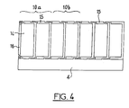
- Each box 14 can be formed by a thin "U" shaped wall 15 which can be fitted onto the wall of the adjacent box, as shown in FIG. 4.
- the boxes 11 or 14 of the lateral end module 10a are closed by a thin vertical wall 16 which fits into the wall in the shape of a "U" 15 constituting said boxes.
- the walls of the boxes 11 or 14 constituting the modules 10a, 10b, 10c ... as well as the base plate 4 are a light material of low density and high resistance.
- This material is a composite material made of carbon fibers or glass fibers and having, for example, a honeycomb structure.
- This arrangement makes it possible to make modular works of great length and of high strength having a volume-to-weight ratio as low as possible.
- the spans according to the invention therefore have qualities of robustness, mechanical solidity and high resistance and have a very particular aptitude for the speed of installation, but also a lightness facilitating their transport and their implementation.
Description
La présente invention a pour objet une travure transportable destinée notamment au franchissement de brèches par des engins dits lourds, par exemple par des engins blindés.The subject of the present invention is a transportable span intended in particular for crossing breaches by so-called heavy vehicles, for example by armored vehicles.
Le franchissement de brèches ou autres passages entre deux bords surélevés par des engins dits lourds réclame des travures présentant non seulement une aptitude toute particulière à la rapidité de pose, mais aussi une légèreté facilitant leur transport et leur mise en oeuvre.The crossing of breaches or other passages between two raised edges by so-called heavy equipment requires spans having not only a very particular aptitude for the speed of installation, but also a lightness facilitating their transport and their implementation.
Ces impératifs de légèreté et de maniabilité sont contradictoires avec les qualités de robustesse, de solidité mécanique et de haute résistance, compte tenu du poids des engins pouvant utiliser ces travures.These imperatives of lightness and maneuverability are contradictory with the qualities of robustness, mechanical solidity and high resistance, taking into account the weight of the machines that can use these spans.
Ces travures sont généralement soit des travures du type en ciseaux, ou soit des travures simples en plusieurs tronçons aboutables.These spans are generally either spans of the scissor type, or either simple spans in several abutable sections.
Les travures de type en ciseaux comprennent deux ou trois éléments qui se développent en rotation dans un plan vertical autour de l'axe commun de deux éléments.The scissor-type span comprises two or three elements which develop in rotation in a vertical plane around the common axis of two elements.
Après déploiement, ces travures peuvent être déposées soit au moyen d'une flèche, soit à l'aide d'un manipulateur.After deployment, these spans can be placed either by means of an arrow or using a manipulator.
Dans le cas d'une travure simple, les tronçons sont transportés de manière superposée les uns par rapport aux autres, puis déplacés en translation par un manipulateur qui, après verrouillage des tronçons, sert également à la dépose de la travure ainsi formée.In the case of a single span, the sections are transported superimposed relative to each other, then moved in translation by a manipulator which, after locking the sections, also serves for the removal of the span thus formed.
Jusqu'à présent les travures de type en ciseaux ou les travures simples sont généralement formées par des poutrelles métalliques soudées de grande section ou par des structures en treillis, si bien que le poids des travures est important ce qui ne facilite pas leur mise en place.Until now, scissor-type structures or simple structures have generally been formed by welded metal beams of large section or by lattice structures, so that the weight spans is important which does not facilitate their installation.
De plus, le poids de ces travures nécessite l'utilisation d'engins de transport et de manoeuvre de grande puissance.In addition, the weight of these structures requires the use of transport and maneuvering equipment of great power.
Or, on sait que le temps de manipulation en chargement et en déchargement et les manoeuvres diverses de mise en place sont des facteurs prépondérants notamment dans le cadre d'opérations rapides.However, it is known that the handling time during loading and unloading and the various installation maneuvers are predominant factors, particularly in the context of rapid operations.
On connaît dans le brevet FR-A-2 409 449, une travure transportable pour le franchissement de brèches comprenant au moins une paire de tronçons parallèles et reliés entre eux pour former un chemin de roulement, chaque tronçon se composant de plusieurs modules solidarisés entre eux. La travure comprend plusieurs paires de tronçons placées bout à bout comportant des moyens de liaison d'un tronçon avec l'autre placé en regard.We know in patent FR-A-2 409 449, a transportable span for crossing breaches comprising at least one pair of parallel sections and connected together to form a raceway, each section consisting of several modules joined together . The span comprises several pairs of sections placed end to end comprising means for connecting one section with the other placed opposite.
L'invention a donc pour but de proposer une travure pour le franchissement de brèches permettant de concilier les qualités de robustesse, de solidité, de résistance mécanique et de légèreté.The invention therefore aims to provide a span for crossing gaps allowing to reconcile the qualities of robustness, solidity, mechanical strength and lightness.
La présente invention a pour objet une travure transportable pour le franchissement de brèches comprenant au moins une paire de tronçons parallèles et reliés entre eux pour former un chemin de roulement, chaque tronçon se composant de plusieurs modules juxtaposés et solidarisés entre eux, en matériau léger de faible densité et de haute résistance, caractérisée en ce chaque module est formé par une succession de caissons placés bout à bout dans le sens de la longueur dudit tronçon et solidarisés entre eux.The subject of the present invention is a transportable span for crossing breaches comprising at least one pair of parallel sections and connected together to form a raceway, each section consisting of several modules juxtaposed and joined together, made of light material of low density and high strength, characterized in that each module is formed by a succession of boxes placed end to end in the direction of the length of said section and secured to each other.
Selon d'autres caractéristiques de l'invention :
- chaque caisson placé bout à bout dans le sens de la longueur est formé par une succession de caissons juxtaposés dans le sens de la largeur dudit caisson et solidarisés entre eux,
- les caissons sont formés par des parois minces emboîtables les unes dans les autres,
- les caissons sont formés par au moins une paroi mince en forme de "U" emboîtable sur la paroi du caisson adjacent,
- les modules reposent sur une plaque de base en matériau léger de faible densité et de haute résistance.
- le matériau léger de faible densité et de haute résistance est un matériau composite,
- le matériau composite est en fibres de carbone,
- le matériau composite est en fibres de verre,
- la matériau composite possède une structure en nid d'abeilles.
- each box placed end to end in the lengthwise is formed by a succession of boxes juxtaposed in the direction of the width of said box and joined together,
- the boxes are formed by thin walls which fit together,
- the boxes are formed by at least one thin wall in the shape of a "U" nestable on the wall of the adjacent box,
- the modules rest on a base plate made of light material of low density and high resistance.
- the light material of low density and high resistance is a composite material,
- the composite material is made of carbon fibers,
- the composite material is made of glass fibers,
- the composite material has a honeycomb structure.
L'invention sera mieux comprise à l'aide de la description qui va suivre donnée uniquement à titre d'exemple et faite en se référant aux dessins annexés sur lesquels :
- la Fig. 1 est une vue de dessus d'une paire de tronçons d'une travure selon l'invention,
- la Fig. 2 est une vue en coupe longitudinale selon la ligne 2-2 de la Fig.1,
- la Fig. 3 est une vue en coupe transversale selon la ligne 3-3 de la Fig. 1,
- la Fig. 4 est une vue en coupe transversale d'un tronçon d'une travure selon un second mode de réalisation.
- Fig. 1 is a top view of a pair of sections of a span according to the invention,
- Fig. 2 is a view in longitudinal section along line 2-2 of FIG. 1,
- Fig. 3 is a cross-sectional view along line 3-3 of FIG. 1,
- Fig. 4 is a cross-sectional view of a section of a span according to a second embodiment.
La travure représentée à la Fig. 1 se compose de plusieurs paires de tronçons 1, les tronçons de chaque paire étant reliés entre eux par des traverses 2.The span shown in FIG. 1 is made up of several pairs of sections 1, the sections of each pair being interconnected by
Pour le franchissement de brèches, plusieurs paires de tronçons 1 peuvent être placées bout à bout pour former au moins un chemin à roulement permettant le passage de véhicules.For crossing breaches, several pairs of sections 1 can be placed end to end to form at least one rolling path allowing the passage of vehicles.
Chaque tronçon 1 est pourvu à chaque extrémité d'un becquet 3 constituant le plan incliné d'accès sur ledit tronçon pour les véhicules et assurant également une bonne stabilité de l'ensemble.Each section 1 is provided at each end with a
Le tronçon 1 se compose de plusieurs modules 10a, 10b, 10c... (Figs. 1 et 2) juxtaposés et solidarisés entre eux par des moyens appropriés non représentés.Section 1 is made up of
Chaque module 10a, 10b, 10c... a la forme d'un caisson de forme générale parallélépipédique dont la face supérieure est légèrement inclinée pour former un profil courbe continu.Each
Les modules 10a, 10b, 10c...reposent sur une plaque de base 4 (Fig. 2).The
Selon un premier mode de réalisation représenté aux Figs. 1 à 3, chaque module 10a, 10b, 10c...est formé par une succession de caissons 14 placés bout à bout dans le sens de la longueur dudit tronçon 1.According to a first embodiment shown in Figs. 1 to 3, each
Chaque caisson 14 comprend deux parois minces verticales 12a, 12b et deux parois minces horizontales 13a, 13b (Fig. 3).Each
Les parois 12a, 12b et 13a, 13b sont assemblées entre elles par des moyens appopriés.The walls 12a, 12b and 13a, 13b are assembled together by suitable means.
Selon encore un second mode de réalisation, chaque caisson 14 placé bout à bout dans le sens de la longueur du tronçon est formé par une succession de caissons juxtaposés dans le sens de la largeur dudit tronçon, lesdits caissons étant solidarisés entre eux par des moyens appropriés.According to yet a second embodiment, each
Chaque caisson 14 peut être formé par une paroi mince en forme "U" 15 emboîtable sur la paroi du caisson adjacent, comme représenté à la Fig. 4.Each
Dans ce cas, les caissons 11 ou 14 du module latéral d'extrémité 10a sont fermés par une paroi mince verticale 16 s'emboîtant dans la paroi en forme de "U" 15 constituant lesdits caissons.In this case, the
Les caissons 11 ou 14 reposent également sur une plaque de base 4.The
Dans tous les cas de figures les parois des caissons 11 ou 14 constituant les modules 10a, 10b, 10c... ainsi que la plaque de base 4 sont un matériau léger de faible densité et de haute résistance.In all cases, the walls of the
Ce matériau est un matériau composite en fibres de carbone ou en fibres de verre et possédant par exemple une structure en nid d'abeilles.This material is a composite material made of carbon fibers or glass fibers and having, for example, a honeycomb structure.
Cette disposition permet de réaliser des travures modulables de grande longueur et de haute résistance possédant un rapport volume-poids le plus faible possible.This arrangement makes it possible to make modular works of great length and of high strength having a volume-to-weight ratio as low as possible.
Les travures selon l'invention possèdent donc des qualités de robustesse, de solidité mécanique et de haute résistance et présentent une aptitude toute particulière à la rapidité de pose, mais aussi une légèreté facilitant leur transport et leur mise en oeuvre.The spans according to the invention therefore have qualities of robustness, mechanical solidity and high resistance and have a very particular aptitude for the speed of installation, but also a lightness facilitating their transport and their implementation.
Claims (9)
- Transportable crossing structure for the bridging of gaps, comprising at least one pair of parallel sections (1) connected to one another to form a runway, each section (1) being composed of a plurality of modules (10a, 10b, 10c, etc) placed next to and fixed to one another and made of a light material of low density and high resistance, characterised in that each module (10a, 10b, 10c, etc.) is formed by a succession of boxes (14) placed end to end in the longitudinal direction of the said section and fixed to one another.
- Crossing structure according to claim 1, characterised in that each box (14) placed end to end in the longitudinal direction is formed by a succession of boxes places next to one another in the direction of width of the said box and fixed to one another.
- Crossing structure according to one of claims 1 and 2, characterised in that the boxes (14) are formed by thin walls (12a, 12b and 13a, 13b) interlockable with one another.
- Crossing structure according to one of Claims 1 and 2, characterised in that the boxes (14) are formed by at least one thin U-shaped wall (15) lockable on the wall (15) of the adjacent box (14).
- Crossing structure according to claim 1, characterised in that the modules (10a, 10b, 10c, etc) rest on a baseplate (4) made of a light material of low density and high resistance.
- Crossing structure according to any of the preceding claims, characterised in that the light material of low density and high resistance is a composite material.
- Crossing structure according to Claim 6 characterised in that the composite material consists of carbon fibres.
- Crossing structure according to Claim 6, characterised in that the composite material consists of glass fibres.
- Crossing structure according to any of claims 6 to 8, characterised in that the composite material possesses a honeycombed structure.
Applications Claiming Priority (2)
| Application Number | Priority Date | Filing Date | Title |
|---|---|---|---|
| FR8917192A FR2656352B1 (en) | 1989-12-26 | 1989-12-26 | TRANSPORTABLE WORK FOR CROSSING BREACHES. |
| FR8917192 | 1989-12-26 |
Publications (2)
| Publication Number | Publication Date |
|---|---|
| EP0435743A1 EP0435743A1 (en) | 1991-07-03 |
| EP0435743B1 true EP0435743B1 (en) | 1993-02-10 |
Family
ID=9388962
Family Applications (1)
| Application Number | Title | Priority Date | Filing Date |
|---|---|---|---|
| EP19900403660 Expired - Lifetime EP0435743B1 (en) | 1989-12-26 | 1990-12-18 | Transportable bridge element for surmounting gaps |
Country Status (6)
| Country | Link |
|---|---|
| EP (1) | EP0435743B1 (en) |
| JP (1) | JPH04261905A (en) |
| CA (1) | CA2033154A1 (en) |
| DE (1) | DE69000909T2 (en) |
| ES (1) | ES2038047T3 (en) |
| FR (1) | FR2656352B1 (en) |
Families Citing this family (3)
| Publication number | Priority date | Publication date | Assignee | Title |
|---|---|---|---|---|
| FR2689155B1 (en) * | 1992-03-25 | 1994-05-20 | Coflexip | FLOOR OR ROOF SUPPORT OF HEAVY LOADS. |
| US7069614B1 (en) * | 1997-02-28 | 2006-07-04 | Manufacturers Equity Trust | Modular span multi-cell box girder bridge system |
| DE102004016983B4 (en) * | 2004-04-07 | 2006-01-19 | Rheinmetall Landsysteme Gmbh | Bridge laying device |
Family Cites Families (4)
| Publication number | Priority date | Publication date | Assignee | Title |
|---|---|---|---|---|
| BE504739A (en) * | 1950-07-20 | |||
| GB843727A (en) * | 1957-08-15 | 1960-08-10 | Ake Hedstrom | Improvements in or relating to bridges |
| GB1137278A (en) * | 1966-09-01 | 1968-12-18 | Secr Defence | Improvements in or relating to bridges |
| GB2011507B (en) * | 1977-11-22 | 1982-02-24 | Westland Aircraft Ltd | Load-supporting structures |
-
1989
- 1989-12-26 FR FR8917192A patent/FR2656352B1/en not_active Expired - Lifetime
-
1990
- 1990-12-18 EP EP19900403660 patent/EP0435743B1/en not_active Expired - Lifetime
- 1990-12-18 DE DE1990600909 patent/DE69000909T2/en not_active Expired - Fee Related
- 1990-12-18 ES ES90403660T patent/ES2038047T3/en not_active Expired - Lifetime
- 1990-12-24 CA CA 2033154 patent/CA2033154A1/en not_active Abandoned
- 1990-12-26 JP JP41836990A patent/JPH04261905A/en active Pending
Also Published As
| Publication number | Publication date |
|---|---|
| FR2656352A1 (en) | 1991-06-28 |
| EP0435743A1 (en) | 1991-07-03 |
| DE69000909T2 (en) | 1993-06-03 |
| ES2038047T3 (en) | 1993-07-01 |
| FR2656352B1 (en) | 1992-07-24 |
| DE69000909D1 (en) | 1993-03-25 |
| CA2033154A1 (en) | 1991-06-27 |
| JPH04261905A (en) | 1992-09-17 |
Similar Documents
| Publication | Publication Date | Title |
|---|---|---|
| EP0802145B1 (en) | Hoisting yoke | |
| FR2533607A1 (en) | T-SHELVING GRID HOUSING FOR SUSPENDED CEILINGS OR SIMILAR ELEMENTS | |
| FR2759063A1 (en) | HANDLING PALLET | |
| BE1009089A5 (en) | Multi-fold structure for work early intervention. | |
| EP1561708B1 (en) | Demountable modular platform for a refuse dump | |
| FR2629111A1 (en) | APRON FOR BRIDGE OF LARGE LENGTH | |
| EP0435743B1 (en) | Transportable bridge element for surmounting gaps | |
| EP0844335A1 (en) | Movable barrier and assembly formed by a set of such barriers | |
| FR2891567A1 (en) | Barrier forming part of a fence preventing vehicular access has concrete base with ring for connecting it by cable to others | |
| FR2546202A1 (en) | PREFABICATED AND EXTERNALLY PRE-STRAPPED DECK BY CABLES, SHOULDERS FOR THIS BRIDGE AND METHODS OF MANUFACTURING SUCH SHOULDERS | |
| FR2649425A1 (en) | BRIDGE SYSTEM FOR CROSSING OBSTACLES SUCH AS BRECH | |
| FR2513214A1 (en) | SIMPLE PALLET | |
| EP0435741B1 (en) | Light transportable bridge element for surmounting gaps | |
| EP2191744B1 (en) | Load taking profile | |
| EP0435742B1 (en) | System for assembling a bridge element for surmounting a gap | |
| FR2793820A1 (en) | Bridgehead for road has ramps inside channel and removable bars extending between channel walls | |
| EP0034541B1 (en) | Flue or vertical pipe for gas discharge | |
| FR2732048A1 (en) | REMOVABLE BRIDGE ASSEMBLED BY SPARE PARTS | |
| EP0463983B1 (en) | Stackable container units for cooking food products | |
| FR2546845A1 (en) | Hatch cover-pontoon for container ships, and container ships equipped with the said cover-pontoon | |
| EP0097088B1 (en) | Floating harbour pontoon for loading or unloading ships, especially roll on, roll off ships | |
| FR2698650A1 (en) | Footbridge for obstacle clearance. | |
| FR2596781A1 (en) | Transportable lightweight bridge-support enabling so-called heavy vehicles, particularly armoured vehicles, to cross gaps | |
| FR2704823A1 (en) | Caterpillar track for a vehicle exhibiting elongate projections | |
| FR2576284A1 (en) | TRANSPORT DEVICE FOR COAL |
Legal Events
| Date | Code | Title | Description |
|---|---|---|---|
| PUAI | Public reference made under article 153(3) epc to a published international application that has entered the european phase |
Free format text: ORIGINAL CODE: 0009012 |
|
| AK | Designated contracting states |
Kind code of ref document: A1 Designated state(s): BE CH DE ES FR GB IT LI NL SE |
|
| 17P | Request for examination filed |
Effective date: 19910718 |
|
| 17Q | First examination report despatched |
Effective date: 19920219 |
|
| GRAA | (expected) grant |
Free format text: ORIGINAL CODE: 0009210 |
|
| AK | Designated contracting states |
Kind code of ref document: B1 Designated state(s): BE CH DE ES FR GB IT LI NL SE |
|
| ITF | It: translation for a ep patent filed |
Owner name: JACOBACCI CASETTA & PERANI S.P.A. |
|
| REF | Corresponds to: |
Ref document number: 69000909 Country of ref document: DE Date of ref document: 19930325 |
|
| GBT | Gb: translation of ep patent filed (gb section 77(6)(a)/1977) |
Effective date: 19930225 |
|
| REG | Reference to a national code |
Ref country code: ES Ref legal event code: FG2A Ref document number: 2038047 Country of ref document: ES Kind code of ref document: T3 |
|
| PLBE | No opposition filed within time limit |
Free format text: ORIGINAL CODE: 0009261 |
|
| STAA | Information on the status of an ep patent application or granted ep patent |
Free format text: STATUS: NO OPPOSITION FILED WITHIN TIME LIMIT |
|
| 26N | No opposition filed | ||
| EAL | Se: european patent in force in sweden |
Ref document number: 90403660.5 |
|
| PGFP | Annual fee paid to national office [announced via postgrant information from national office to epo] |
Ref country code: NL Payment date: 19951117 Year of fee payment: 6 |
|
| PGFP | Annual fee paid to national office [announced via postgrant information from national office to epo] |
Ref country code: CH Payment date: 19951128 Year of fee payment: 6 |
|
| PGFP | Annual fee paid to national office [announced via postgrant information from national office to epo] |
Ref country code: SE Payment date: 19951218 Year of fee payment: 6 |
|
| PGFP | Annual fee paid to national office [announced via postgrant information from national office to epo] |
Ref country code: ES Payment date: 19951220 Year of fee payment: 6 Ref country code: BE Payment date: 19951220 Year of fee payment: 6 |
|
| PG25 | Lapsed in a contracting state [announced via postgrant information from national office to epo] |
Ref country code: SE Effective date: 19961219 |
|
| PG25 | Lapsed in a contracting state [announced via postgrant information from national office to epo] |
Ref country code: LI Effective date: 19961231 Ref country code: CH Effective date: 19961231 Ref country code: BE Effective date: 19961231 |
|
| BERE | Be: lapsed |
Owner name: FRAMATOME Effective date: 19961231 |
|
| PG25 | Lapsed in a contracting state [announced via postgrant information from national office to epo] |
Ref country code: NL Effective date: 19970701 |
|
| REG | Reference to a national code |
Ref country code: CH Ref legal event code: PL |
|
| NLV4 | Nl: lapsed or anulled due to non-payment of the annual fee |
Effective date: 19970701 |
|
| EUG | Se: european patent has lapsed |
Ref document number: 90403660.5 |
|
| PG25 | Lapsed in a contracting state [announced via postgrant information from national office to epo] |
Ref country code: ES Free format text: LAPSE BECAUSE OF NON-PAYMENT OF DUE FEES Effective date: 19971219 |
|
| PGFP | Annual fee paid to national office [announced via postgrant information from national office to epo] |
Ref country code: FR Payment date: 19981202 Year of fee payment: 9 |
|
| PGFP | Annual fee paid to national office [announced via postgrant information from national office to epo] |
Ref country code: GB Payment date: 19981203 Year of fee payment: 9 |
|
| PGFP | Annual fee paid to national office [announced via postgrant information from national office to epo] |
Ref country code: DE Payment date: 19981204 Year of fee payment: 9 |
|
| PG25 | Lapsed in a contracting state [announced via postgrant information from national office to epo] |
Ref country code: GB Free format text: LAPSE BECAUSE OF NON-PAYMENT OF DUE FEES Effective date: 19991218 |
|
| GBPC | Gb: european patent ceased through non-payment of renewal fee |
Effective date: 19991218 |
|
| PG25 | Lapsed in a contracting state [announced via postgrant information from national office to epo] |
Ref country code: FR Free format text: LAPSE BECAUSE OF NON-PAYMENT OF DUE FEES Effective date: 20000831 |
|
| PG25 | Lapsed in a contracting state [announced via postgrant information from national office to epo] |
Ref country code: DE Free format text: LAPSE BECAUSE OF NON-PAYMENT OF DUE FEES Effective date: 20001003 |
|
| REG | Reference to a national code |
Ref country code: FR Ref legal event code: ST |
|
| REG | Reference to a national code |
Ref country code: ES Ref legal event code: FD2A Effective date: 19980113 |
|
| PG25 | Lapsed in a contracting state [announced via postgrant information from national office to epo] |
Ref country code: IT Free format text: LAPSE BECAUSE OF NON-PAYMENT OF DUE FEES;WARNING: LAPSES OF ITALIAN PATENTS WITH EFFECTIVE DATE BEFORE 2007 MAY HAVE OCCURRED AT ANY TIME BEFORE 2007. THE CORRECT EFFECTIVE DATE MAY BE DIFFERENT FROM THE ONE RECORDED. Effective date: 20051218 |