EP0435549B1 - Tête d'impression à orifices pour imprimante électrostatique directe - Google Patents
Tête d'impression à orifices pour imprimante électrostatique directe Download PDFInfo
- Publication number
- EP0435549B1 EP0435549B1 EP90313851A EP90313851A EP0435549B1 EP 0435549 B1 EP0435549 B1 EP 0435549B1 EP 90313851 A EP90313851 A EP 90313851A EP 90313851 A EP90313851 A EP 90313851A EP 0435549 B1 EP0435549 B1 EP 0435549B1
- Authority
- EP
- European Patent Office
- Prior art keywords
- toner
- printhead
- apertures
- openings
- delivery system
- Prior art date
- Legal status (The legal status is an assumption and is not a legal conclusion. Google has not performed a legal analysis and makes no representation as to the accuracy of the status listed.)
- Expired - Lifetime
Links
Images

Classifications
-
- B—PERFORMING OPERATIONS; TRANSPORTING
- B41—PRINTING; LINING MACHINES; TYPEWRITERS; STAMPS
- B41J—TYPEWRITERS; SELECTIVE PRINTING MECHANISMS, i.e. MECHANISMS PRINTING OTHERWISE THAN FROM A FORME; CORRECTION OF TYPOGRAPHICAL ERRORS
- B41J2/00—Typewriters or selective printing mechanisms characterised by the printing or marking process for which they are designed
- B41J2/385—Typewriters or selective printing mechanisms characterised by the printing or marking process for which they are designed characterised by selective supply of electric current or selective application of magnetism to a printing or impression-transfer material
- B41J2/41—Typewriters or selective printing mechanisms characterised by the printing or marking process for which they are designed characterised by selective supply of electric current or selective application of magnetism to a printing or impression-transfer material for electrostatic printing
- B41J2/415—Typewriters or selective printing mechanisms characterised by the printing or marking process for which they are designed characterised by selective supply of electric current or selective application of magnetism to a printing or impression-transfer material for electrostatic printing by passing charged particles through a hole or a slit
- B41J2/4155—Typewriters or selective printing mechanisms characterised by the printing or marking process for which they are designed characterised by selective supply of electric current or selective application of magnetism to a printing or impression-transfer material for electrostatic printing by passing charged particles through a hole or a slit for direct electrostatic printing [DEP]
Definitions
- This invention relates to a direct electrostatic printing device and more particularly to an apertured printhead structure utilized for depositing developer or toner in image configuration on plain paper substrates.
- a less familiar form of electrostatic printing is one that has come to be known as direct electrostatic printing (DEP).
- DEP direct electrostatic printing
- This form of printing differs from the aforementioned xerographic form, in that, the toner or developing material is deposited directly onto a plain (i.e. not specially treated) substrate in image configuration.
- This type of printing device is disclosed in US-A-3,689,935 ( Pressman et al.).
- Pressman et a disclose an electrostatic line printer incorporating a multilayered particle modulator or printhead comprising a layer of insulating material, a continuous layer of conducting material on one side of the insulating layer and a segmented layer of conducting material on the other side of the insulating layer. At least one row of apertures is formed through the multilayered particle modulator. Each segment of the segmented layer of the conductive material is formed around a portion of an aperture and is insulatively isolated from every other segment of the segmented conductive layer. Selected potentials are applied to each of the segments of the segmented conductive layer while a fixed potential is applied to the continuous conductive layer.
- An overall applied field projects charged particles through the row of apertures of the particle modulator and the density of the particle stream is modulated according to the the pattern of potentials applied to the segments of the segmented conductive layer.
- the modulated stream of charged particles impinge upon a print-receiving medium interposed in the modulated particle stream and translated relative to the particle modulator to provide line-by-line scan printing.
- the supply of the toner to the control member is not uniformly effected and irregularities are liable to occur in the image on the image receiving member. High-speed recording is difficult and moreover, the openings in the printhead are liable to be clogged by the toner.
- US-A-4,491,855 discloses a method and apparatus utilizing a controller having a plurality of openings or slit-like openings to control the passage of one-component insulative magnetic toner and to record a visible image by the charged particles directly on an image receiving member.
- Fujii, et al. show an apertured printhead structure having wedge-shaped apertures wherein the larger diameter of an aperture is delineated by a signal or control electrode and is disposed opposite an image receiving substrate.
- US-A-4,568 955 discloses a recording apparatus wherein a visible image based on image information is formed on an ordinary sheet by a developer.
- the recording apparatus comprises a developing roller spaced at a predetermined distance from and facing the ordinary sheet and carrying the developer thereon. It further comprises a recording electrode and a signal source connected thereto for propelling the developer on the developing roller to the ordinary sheet by generating an electric field between the ordinary sheet and the developing roller according to the image information.
- a plurality of mutually insulated electrodes are provided on the developing roller and extend therefrom in one direction.
- a toner reservoir is disposed beneath a recording electrode which has a top provided with an opening facing the recording electrode and an inclined bottom for holding a quantity of toner.
- a toner carrying plate as the developer carrying member, secured in a position such that it faces the end of the recording electrode at a predetermined distance therefrom and a toner agitator for agitating the toner.
- the printhead structure therein is constructed such that the control electrodes thereof are disposed opposite the toner supply resulting in reduced control voltage requirements.
- the present invention is intended to provide an improved direct electrostatic printing device.
- an apparatus for forming images including a toner delivery system, a printhead structure containing a plurality of apertures adapted to transport toner therethrough which toner is supplied by said delivery system to the vicinity of said apertures and means for supporting image receiving substrates for movement past said printhead, said supporting means being adapted to attract toner transported from said delivery system through said printhead whereby said toner is deposited in image configuration on said image receiving substrate, and the printhead structure having control electrodes with openings therein and a shield electrode structure having openings therein, and said openings delineating said apertures; characterised by said printhead structure being constructed such that said control electrodes have a greater influence on the barrier potential in said apertures than said shield electrode.
- the present invention provides a developer or toner delivery system disposed to one side of a printhead and an electrically biased shoe or electrode which is disposed to the opposite side of the printhead from the toner delivery system.
- the printhead structure comprises a sandwich-like structure including an insluative base member having control electrodes carried by one side thereof and a shield electrode carried by the other side. Apertures extending through the printhead structure are delimited by circular openings in the control electrodes and corresponding circular openings n the shield electrode and base member.
- the openings for the control electrodes have a smaller radius than a corresponding opening in the shield electrode.
- the printhead structure having the foregoing hole configuration provides significant advantages over that of Fujii et al, in that, toner supply modulation can be achieved with lower switching voltages. Another advantage is the minimization of the accumulation rate of wrong sign toner on the printhead structure. Also, the positioning of the larger diameter of the aperture adjacent the toner supply provides for better toner collection resulting in improved toner flow due to increased toner cloud densities and hence print speed.
- Figure 1 Disclosed in Figure 1 is an embodiment of a direct electrostatic printing apparatus 10 representing the invention.
- the printing apparatus 10 includes a developer delivery system generally indicated by reference character 12, a printhead structure 14 and a backing electrode or shoe 16.
- the developer delivery system 12 includes a conventional magnetic brush 18 supported for rotation adjacent a supply of toner 20 contained in a hopper 22.
- a developer donor roll 24 is supported for rotation intermediate the magnetic brush 18 and the printhead structure 14.
- the donor roll structure is coated with Teflon-S (Trademark of E.I. dupont) is spaced from the printhead approximately 75 to 375 »m.
- Teflon-S is a tetrafluoroethylene fluorocarbon polymer that is loaded with carbon black.
- the magnetic brush has a dc bias of about 200 volts applied thereto via a dc voltage source 26.
- An AC voltage of about 400 volts at 3 kHz provided by source 28 with a dc bias of 20 volts provided by source 29 is applied to the donor roll 24.
- the applied voltages are effective to cause transfer of a monolayer of toner from the brush 18 to the donor roll 24.
- the monolayer is subsequently jumped to the vicinity of the apertures of the printhead.
- the 20 volts dc bias precludes collection of right sign toner on the shield electrode of the printhead.
- the developer preferably comprises any suitable insulative non-magnetic toner/carrier combination having Aerosil (Trademark of Degussa, Inc.) contained therein in an amount equal to 1/2% by weight and also having zinc stearate contained therein in an amount equal to 1% by weight.
- Aerosil Trademark of Degussa, Inc.
- zinc stearate contained therein in an amount equal to 1% by weight.
- the printhead structure 14 comprises a layered member including an electrically insulative base member 31 fabricated from a polyimide film approximately 25 »m thick.
- the base member is clad on the one side thereof with a continuous conductive layer or shield 32 of aluminum which is approximately one micron thick.
- the opposite side of the base member 30 carries segmented conductive layer 34 thereon which is fabricated from aluminum.
- a plurality of holes or apertures 36, (only one of which is shown) approximately 0.15 mm in diameter are provided in the layered structure in a pattern suitable for use in recording information.
- the apertures form an electrode array of individually addressable electrodes. With the shield grounded and zero to + 50 volts applied to an addressable electrode, toner is propelled through the aperture associated with that electrode.
- the aperture extends through the base 31 and the conductive layers 32 and 34.
- Image intensity can be varied by adjusting the voltage on the control electrodes between 0 and minus 300 volts. Addressing of the individual electrodes can be effected in any well known manner know in the art of printing using electronically addressable printing elements.
- the electrode or shoe 16 has an arcuate shape as shown but as will be appreciated, the present invention is not limited by such a configuration.
- the shoe which is positioned on the opposite side of a plain paper recording medium 30 from the printhead deflects the recording medium in order to provide an extended area of contact between the medium and the shoe.
- the recording medium 30 may comprise cut sheets of paper fed from a supply tray, not shown.
- the sheets of paper are spaced from the printhead 14 a distance in the order of 75 to 750 »m as they pass therebetween.
- the sheets 30 are transported in contact with the shoe 16 via edge transport roll pairs 42.
- the shoe 16 is electrically biased to a dc potential of approximately 400 volts via a dc voltage source 38.
- a switch 40 Periodically, between the printing of successive pages, a switch 40 is actuated in the absence of a sheet of paper between the printhead and the shoe such that a dc biased AC power supply 43 is connected to the shoe 16 to effect cleaning of the printhead.
- the voltage supplied by the source 43 is of the same frequency as that (i.e. source 28) used to jump the toner from the toner supply system but it is 180 degrees out of phase with it. This causes the toner in the gap between the paper and the printhead to oscillate and bombard the printhead.
- a fuser assembly At the fusing station, a fuser assembly, indicated generally by the reference numeral 54, permanently affixes the transferred toner powder images to sheet 30.
- fuser assembly 54 includes a heated fuser roller 56 adapted to be pressure engaged with a back-up roller 58 with the toner powder images contacting fuser roller 56. In this manner, the toner powder image is permanently affixed to copy substrate 30.
- chute After fusing, chute, not shown, guides the advancing sheet 30 to a catch tray (not shown) for removal from the printing machine by the operator.
- the apertures 36 are delineated by circular openings 70 (Figure 2) in the control electrodes and corresponding circular openings 72 in the shield electrode. Openings 76 in the base member provide a toner flow path between the openings 70 and 72.
- the radius of an opening 70 in a control electrode 34 is smaller than the corresponding opening 72 in the the shield electrode.
- the apertures illustrated in Figure 2 are tapered away from the doner roll 24, and thus appear to have a wedge shape.
- a modified printhead aperture configuration as illustrated in Figure 3 comprises a penetrating control electrode structure 78 and a shield electrode structure 79.
- penetrating it is meant that the control electrode extends through the aperture 80 and is partially in contact with the side of the base member occupied by the shield electrode 79.
- the radius of the the control electrode opening, through the aperture is approximately 75 »m and the radius of the portion of the control electrode which is secured to the same side of the base member 31 as the shield electrode is approximately 100 »m.
- the control electrodes openings have a smaller radius than the shield electrode openings and are disposed opposite the toner supply.
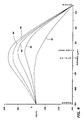
- Figure 4 illustrates plots of the DC component of electrostatic potential versus distance along a path from the toned donor 24 to the imaging substrate 30 through the center of a printhead aperture configuration as shown in Figures 2 and 3 and perpendicular to the printhead.
- the plot in Figure 4 and the discussions to follow relating thereto directly apply to a case where the polarity of the toner is positive. These same plots also apply to negative toner if the sign of the voltage is reversed. Thus, a set of electrode voltages giving rise to a given plot in Figure 4 will produce the same effect on negative toner if all the electrode voltages are reversed.
- the control voltage must be changed from + 300 to -300 volts.
- Negative toner was tacitly assumed in all examples discussed hereinabove.
- the curve 82 represents a toner flow or "On" condition where 0 volts are applied to the control and shield electrodes.
- the printhead structure for this example is spaced, as indicated in Figure 3, 150 »m from both the donor roll and the imaging receiving paper and has a total thickness of 25 »m. Also, with 0 volts applied to the control electrode, a -40 volts is applied to the donor roll and -300 volts is applied to the backside of the image receiving surface.
- the voltages for the donor roll, paper shoe and shield electrode are the same for curves 84, 86, 88 and 90 but the control voltage is set to a + 300 volts.
- the curves 84, 88 and 90 represent typical "OFF" states for the printhead structures of the present invention. Curves 84 and 88 are for an aperture as shown in Figure 2 while curve 90 is for an aperture structure as shown in Figure 3.
- the curve 86 represents the "OFF" state for a prior art printhead aperture configuration.
- the radius of the control electrode is smaller than its corresponding shield opening radius whereas in the case of curve 86 the radius of the control electrode is larger than a corresponding shield opening radius or the radii of the shield and control electrodes are the reverse of those for curve 84.
- the control electrode opening is 75 »m.
- the shield radii for curves 84 and 88 are 90 and 140 »m respectively.
- the shield radius is 125 »m while the radii of the smaller control electrodes extend from 75 to 100 »m on the shield side of the printhead.
- the aperture configuration of the present invention results in a higher peak potential (i.e. voltage which acts as a barrier to toner flow through an aperture) of 105 volts compared to 48 volts for an aperture configuration fabricated in accordance with that known in the prior art where the control opening radius is larger than a corresponding shield opening radius
- a gain of better than 2 to 1 in peak voltage sensitivity is attained by the aperture configuration of the present invention.
- the same toner flow shutoff voltage can be attained with a much smaller control voltage.
- use of the same control voltage with the same toner enables the use of greater toner cloud densities thereby improving printing speed and reduced aperture fouling rate (i.e. greater wrong sign toner tolerance).
- Curve 88 depicts the effect on the peak potential when the shield opening is increased to 140 »m while curve 90 depicts the effect on peak potential when the control electrode extends through an aperture configuration according to the embodiment depicted in Figure 3.
- the shield radius is 125 »m while the control electrode extends through the 75 »m opening out to the radius of 100 »m.
- the shield radius increases the control barrier voltage increases.
- the radius of the shield openings is limited because the isolation between neighboring apertures becomes less and less resulting in crosstalk between apertures.
Claims (9)
- Appareil pour former des images comprenant un système de délivrance de toner (10), une structure de tête d'impression (14) contenant une multitude d'orifices (36) destinés à transporter du toner par leur intermédiaire, toner qui est fourni par ledit système de délivrance au voisinage desdits orifices, et un moyen (16) pour supporter des substrats de réception d'image (30) pour mouvement au droit de ladite tête d'impression, ledit moyen de support étant destiné à attirer du toner transporté à partir dudit système de délivrance par l'intermédiaire de ladite tête d'impression, d'où il résulte que ledit toner est déposé dans une configuration d'image sur ledit substrat de réception d'image, et la structure de la tête d'impression ayant des électrodes de commande (34) avec des ouvertures pratiquées intérieurement et une structure d'électrode de protection (32) ayant des ouvertures ménagées intérieurement, et lesdites ouvertures délimitant lesdits orifices; caractérisé en ce que :
ladite structure de la tête d'impression est construite de façon que lesdites électrodes de commande (34) aient une influence plus grande sur le potentiel de barrière dans lesdits orifices (36) que ladite électrode de protection (32). - Appareil selon la revendication 1, dans lequel lesdites électrode de commande et structure d'électrode de protection sont fixées aux côtés opposés d'un élément de base (31).
- Appareil selon la revendication 1 ou la revendication 2, dans lequel lesdites ouvertures (76) délimitant lesdits orifices sont construites d'une façon telle que les électrodes de commande (70) présentent une influence plus grande sur le potentiel barrière dans lesdits orifices que ladite électrode de protection (72).
- Appareil selon la revendication 3, dans lequel lesdites ouvertures ont des dimensions différentes, ladite structure de la tête d'impression étant placée de façon que la plus grande (72) desdites ouvertures soit opposée audit système de délivrance de toner.
- Appareil selon la revendication 4, dans lequel une ouverture ménagée dans ladite électrode de commande (70) a un rayon plus petit que celui d'une ouverture correspondante pratiquée dans ladite électrode de protection (72).
- Appareil selon la revendication 4 ou la revendication 5, dans lequel lesdites ouvertures sont diminuent à partir dudit système de délivrance de toner (10).
- Appareil selon la revendication 3 ou la revendication 4, dans lequel lesdites électrodes de commande (78) s'étendent à travers lesdits orifices (80).
- Appareil selon la revendication 7, dans lequel une partie desdites électrodes de commande (78) ont la même longueur qu'une partie du côté dudit élément de base (31) auquel ladite structure d'électrode de protection (79) est fixée.
- Appareil selon l'une quelconque des revendications 1 à 8, dans lequel ledit système de délivrance de toner (10) comprend du toner amagnétique isolant.
Applications Claiming Priority (2)
| Application Number | Priority Date | Filing Date | Title |
|---|---|---|---|
| US452159 | 1989-12-18 | ||
| US07/452,159 US5038159A (en) | 1989-12-18 | 1989-12-18 | Apertured printhead for direct electrostatic printing |
Publications (3)
| Publication Number | Publication Date |
|---|---|
| EP0435549A2 EP0435549A2 (fr) | 1991-07-03 |
| EP0435549A3 EP0435549A3 (en) | 1992-01-15 |
| EP0435549B1 true EP0435549B1 (fr) | 1995-03-29 |
Family
ID=23795296
Family Applications (1)
| Application Number | Title | Priority Date | Filing Date |
|---|---|---|---|
| EP90313851A Expired - Lifetime EP0435549B1 (fr) | 1989-12-18 | 1990-12-18 | Tête d'impression à orifices pour imprimante électrostatique directe |
Country Status (4)
| Country | Link |
|---|---|
| US (1) | US5038159A (fr) |
| EP (1) | EP0435549B1 (fr) |
| JP (1) | JPH03196062A (fr) |
| DE (1) | DE69018222T2 (fr) |
Families Citing this family (55)
| Publication number | Priority date | Publication date | Assignee | Title |
|---|---|---|---|---|
| US5270742A (en) * | 1990-06-07 | 1993-12-14 | Olympus Optical Co., Ltd. | Image forming apparatus for forming electrostatic latent image using ions as medium, with high-speed driving means |
| US5296879A (en) * | 1990-07-09 | 1994-03-22 | Brother Kogyo Kabushiki Kaisha | Image recording apparatus having detachable cartridge |
| JPH0577475A (ja) * | 1991-09-20 | 1993-03-30 | Brother Ind Ltd | 画像形成装置 |
| US5204696A (en) * | 1991-12-16 | 1993-04-20 | Xerox Corporation | Ceramic printhead for direct electrostatic printing |
| US5508723A (en) * | 1992-09-01 | 1996-04-16 | Brother Kogyo Kabushiki Kaisha | Electric field potential control device for an image forming apparatus |
| US5515084A (en) * | 1993-05-18 | 1996-05-07 | Array Printers Ab | Method for non-impact printing utilizing a multiplexed matrix of controlled electrode units and device to perform method |
| JPH07125297A (ja) * | 1993-11-01 | 1995-05-16 | Brother Ind Ltd | 画像形成装置 |
| US6206672B1 (en) * | 1994-03-31 | 2001-03-27 | Edward P. Grenda | Apparatus of fabricating 3 dimensional objects by means of electrophotography, ionography or a similar process |
| SE503955C2 (sv) * | 1994-09-19 | 1996-10-07 | Array Printers Ab | Metod och anordning för matning av tonerpartiklar i en printerenhet |
| WO1996018506A1 (fr) * | 1994-12-15 | 1996-06-20 | Array Printers Ab | Systeme d'impression en serie a depot direct de particules de poudre |
| US5818480A (en) * | 1995-02-14 | 1998-10-06 | Array Printers Ab | Method and apparatus to control electrodes in a print unit |
| JPH08310035A (ja) * | 1995-05-16 | 1996-11-26 | Brother Ind Ltd | 画像形成装置 |
| EP0753413B1 (fr) * | 1995-07-14 | 1999-12-01 | Agfa-Gevaert N.V. | Structure de tête d'impression pour l'utilisation dans un dispositif DEP |
| US6000786A (en) * | 1995-09-19 | 1999-12-14 | Array Printers Publ. Ab | Method and apparatus for using dual print zones to enhance print quality |
| SE506484C2 (sv) | 1996-03-12 | 1997-12-22 | Ito Engineering Ab | Tryckverk av toner-jet-typ med elektriskt skärmad matris |
| SE506483C2 (sv) | 1996-03-12 | 1997-12-22 | Ito Engineering Ab | Tryckverk av toner-jet typ |
| US5847733A (en) * | 1996-03-22 | 1998-12-08 | Array Printers Ab Publ. | Apparatus and method for increasing the coverage area of a control electrode during direct electrostatic printing |
| US5971526A (en) * | 1996-04-19 | 1999-10-26 | Array Printers Ab | Method and apparatus for reducing cross coupling and dot deflection in an image recording apparatus |
| US5818490A (en) * | 1996-05-02 | 1998-10-06 | Array Printers Ab | Apparatus and method using variable control signals to improve the print quality of an image recording apparatus |
| US5880760A (en) * | 1996-06-06 | 1999-03-09 | Agfa-Gevaert | Method and device for printing information on substrates having security features |
| US6059398A (en) * | 1996-06-11 | 2000-05-09 | Agfa-Gevaert | Printhead structure having electrodes not extending to the edge of printing apertures |
| EP0812696B1 (fr) * | 1996-06-11 | 1998-05-06 | Agfa-Gevaert N.V. | Structure de tête d'impression avec une électrode d'écran spécifique |
| US5774159A (en) * | 1996-09-13 | 1998-06-30 | Array Printers Ab | Direct printing method utilizing continuous deflection and a device for accomplishing the method |
| US5956064A (en) * | 1996-10-16 | 1999-09-21 | Array Printers Publ. Ab | Device for enhancing transport of proper polarity toner in direct electrostatic printing |
| US5966152A (en) * | 1996-11-27 | 1999-10-12 | Array Printers Ab | Flexible support apparatus for dynamically positioning control units in a printhead structure for direct electrostatic printing |
| US5959648A (en) * | 1996-11-27 | 1999-09-28 | Array Printers Ab | Device and a method for positioning an array of control electrodes in a printhead structure for direct electrostatic printing |
| US5889542A (en) * | 1996-11-27 | 1999-03-30 | Array Printers Publ. Ab | Printhead structure for direct electrostatic printing |
| US5984456A (en) * | 1996-12-05 | 1999-11-16 | Array Printers Ab | Direct printing method utilizing dot deflection and a printhead structure for accomplishing the method |
| US6011944A (en) * | 1996-12-05 | 2000-01-04 | Array Printers Ab | Printhead structure for improved dot size control in direct electrostatic image recording devices |
| US6012801A (en) | 1997-02-18 | 2000-01-11 | Array Printers Ab | Direct printing method with improved control function |
| JP2001514587A (ja) * | 1997-03-10 | 2001-09-11 | アライ プリンターズ アクチボラゲット | 制御機能を改善した直接印刷方法 |
| JPH11320873A (ja) * | 1997-06-05 | 1999-11-24 | Ricoh Co Ltd | インクジェットヘッド |
| US6017115A (en) * | 1997-06-09 | 2000-01-25 | Array Printers Ab | Direct printing method with improved control function |
| US6132029A (en) * | 1997-06-09 | 2000-10-17 | Array Printers Ab | Direct printing method with improved control function |
| EP0895867A3 (fr) * | 1997-08-07 | 1999-03-31 | Agfa-Gevaert N.V. | Appareil d'impression électrostatique directe comprenant une électrode de bord et un champ de courant alternatif sur la surface des moyens d'alimentation en toner |
| US6102526A (en) * | 1997-12-12 | 2000-08-15 | Array Printers Ab | Image forming method and device utilizing chemically produced toner particles |
| US6027206A (en) * | 1997-12-19 | 2000-02-22 | Array Printers Ab | Method and apparatus for cleaning the printhead structure during direct electrostatic printing |
| US6209990B1 (en) | 1997-12-19 | 2001-04-03 | Array Printers Ab | Method and apparatus for coating an intermediate image receiving member to reduce toner bouncing during direct electrostatic printing |
| US6030070A (en) * | 1997-12-19 | 2000-02-29 | Array Printers Ab | Direct electrostatic printing method and apparatus |
| US6070967A (en) * | 1997-12-19 | 2000-06-06 | Array Printers Ab | Method and apparatus for stabilizing an intermediate image receiving member during direct electrostatic printing |
| US6086186A (en) * | 1997-12-19 | 2000-07-11 | Array Printers Ab | Apparatus for positioning a control electrode array in a direct electrostatic printing device |
| US6257708B1 (en) | 1997-12-19 | 2001-07-10 | Array Printers Ab | Direct electrostatic printing apparatus and method for controlling dot position using deflection electrodes |
| US6199971B1 (en) | 1998-02-24 | 2001-03-13 | Arrray Printers Ab | Direct electrostatic printing method and apparatus with increased print speed |
| US6074045A (en) * | 1998-03-04 | 2000-06-13 | Array Printers Ab | Printhead structure in an image recording device |
| US6174048B1 (en) | 1998-03-06 | 2001-01-16 | Array Printers Ab | Direct electrostatic printing method and apparatus with apparent enhanced print resolution |
| US6082850A (en) * | 1998-03-19 | 2000-07-04 | Array Printers Ab | Apparatus and method for controlling print density in a direct electrostatic printing apparatus by adjusting toner flow with regard to relative positioning of rows of apertures |
| US6081283A (en) * | 1998-03-19 | 2000-06-27 | Array Printers Ab | Direct electrostatic printing method and apparatus |
| US6102525A (en) * | 1998-03-19 | 2000-08-15 | Array Printers Ab | Method and apparatus for controlling the print image density in a direct electrostatic printing apparatus |
| EP0965455A1 (fr) | 1998-06-15 | 1999-12-22 | Array Printers Ab | Méthode et appareil d'impression électrostatique directe |
| EP0965894B1 (fr) | 1998-06-15 | 2002-03-27 | Array Printers Ab | Procédé et dispositif d'impression électrostatique directe |
| DE10030166A1 (de) * | 2000-06-20 | 2002-01-03 | Heidelberger Druckmasch Ag | Verfahren zum Reinigen eines elektrografischen Schreibkopfes und Vorrichtung zum Erzeugen eines elektrostatischen Musters |
| CA2450361A1 (fr) * | 2001-06-26 | 2003-01-09 | Tiger Microsystems, Inc. | Procede et appareil de depot electrostatique de poudre seche |
| US6883900B2 (en) | 2001-10-18 | 2005-04-26 | Fuji Photo Film Co., Ltd. | Image forming method and image forming apparatus |
| US7261542B2 (en) | 2004-03-18 | 2007-08-28 | Desktop Factory, Inc. | Apparatus for three dimensional printing using image layers |
| US8771802B1 (en) | 2012-04-20 | 2014-07-08 | Xactiv, Inc. | Device and materials fabrication and patterning via shaped slot electrode control of direct electrostatic powder deposition |
Citations (2)
| Publication number | Priority date | Publication date | Assignee | Title |
|---|---|---|---|---|
| US491855A (en) * | 1893-02-14 | Gas-engine | ||
| US568955A (en) * | 1896-10-06 | Mail-crane |
Family Cites Families (7)
| Publication number | Priority date | Publication date | Assignee | Title |
|---|---|---|---|---|
| US3689935A (en) * | 1969-10-06 | 1972-09-05 | Electroprint Inc | Electrostatic line printer |
| JPS5040616B1 (fr) * | 1970-03-18 | 1975-12-25 | ||
| US4338614A (en) * | 1979-10-22 | 1982-07-06 | Markem Corporation | Electrostatic print head |
| US4491855A (en) * | 1981-09-11 | 1985-01-01 | Canon Kabushiki Kaisha | Image recording method and apparatus |
| JPS58194058A (ja) * | 1982-05-08 | 1983-11-11 | Canon Inc | 画像記録装置 |
| US4568955A (en) * | 1983-03-31 | 1986-02-04 | Tokyo Shibaura Denki Kabushiki Kaisha | Recording apparatus using a toner-fog generated by electric fields applied to electrodes on the surface of the developer carrier |
| US4658269A (en) * | 1986-06-02 | 1987-04-14 | Xerox Corporation | Ink jet printer with integral electrohydrodynamic electrodes and nozzle plate |
-
1989
- 1989-12-18 US US07/452,159 patent/US5038159A/en not_active Expired - Fee Related
-
1990
- 1990-11-30 JP JP2341212A patent/JPH03196062A/ja active Pending
- 1990-12-18 DE DE69018222T patent/DE69018222T2/de not_active Expired - Fee Related
- 1990-12-18 EP EP90313851A patent/EP0435549B1/fr not_active Expired - Lifetime
Patent Citations (2)
| Publication number | Priority date | Publication date | Assignee | Title |
|---|---|---|---|---|
| US491855A (en) * | 1893-02-14 | Gas-engine | ||
| US568955A (en) * | 1896-10-06 | Mail-crane |
Also Published As
| Publication number | Publication date |
|---|---|
| JPH03196062A (ja) | 1991-08-27 |
| EP0435549A2 (fr) | 1991-07-03 |
| US5038159A (en) | 1991-08-06 |
| DE69018222D1 (de) | 1995-05-04 |
| EP0435549A3 (en) | 1992-01-15 |
| DE69018222T2 (de) | 1995-11-09 |
Similar Documents
| Publication | Publication Date | Title |
|---|---|---|
| EP0435549B1 (fr) | Tête d'impression à orifices pour imprimante électrostatique directe | |
| US5095322A (en) | Avoidance of DEP wrong sign toner hole clogging by out of phase shield bias | |
| EP0376669B1 (fr) | Appareil d'impression électrostatique | |
| EP0266961B1 (fr) | Appareil d'impression électrostatique direct et ensemble de distribution de toner-développateur pour cet appareil | |
| EP0266960B1 (fr) | Appareil d'impression électrostatique direct et ensemble de nettoyage de la tête d'impression pour cet appareil | |
| US4903050A (en) | Toner recovery for DEP cleaning process | |
| US5214451A (en) | Toner supply leveling in multiplexed DEP | |
| CA1326055C (fr) | Imprimante et dispositif d'alimentation en poudre imprimante | |
| US4860036A (en) | Direct electrostatic printer (DEP) and printhead structure therefor | |
| US4780733A (en) | Printing apparatus and toner/developer delivery system therefor | |
| US5040004A (en) | Belt donor for direct electrostatic printing | |
| EP0415700B1 (fr) | Dispositif pour retirer le toneur chargé avec la mauvaise polarité dans une imprimante électrostatique directe | |
| US4949103A (en) | Direct electrostatic printing apparatus and method for making labels | |
| EP0389229A2 (fr) | Appareil de formation d'images | |
| US5327169A (en) | Masked magnetic brush direct writing for high speed and color printing | |
| CA2135704C (fr) | Cassette de developpement a toner | |
| EP0415701B1 (fr) | Appareil d'impression et procédé pour la formation d'images sur un substrat | |
| US5136311A (en) | Apertureless direct electrostatic printer | |
| EP0501739B1 (fr) | Appareil d'impression électrostatique et procédé | |
| JPH05138927A (ja) | 多数ヘツド形直接静電印刷の高速化装置 |
Legal Events
| Date | Code | Title | Description |
|---|---|---|---|
| PUAI | Public reference made under article 153(3) epc to a published international application that has entered the european phase |
Free format text: ORIGINAL CODE: 0009012 |
|
| AK | Designated contracting states |
Kind code of ref document: A2 Designated state(s): DE FR GB |
|
| PUAL | Search report despatched |
Free format text: ORIGINAL CODE: 0009013 |
|
| AK | Designated contracting states |
Kind code of ref document: A3 Designated state(s): DE FR GB |
|
| 17P | Request for examination filed |
Effective date: 19920702 |
|
| 17Q | First examination report despatched |
Effective date: 19940517 |
|
| GRAA | (expected) grant |
Free format text: ORIGINAL CODE: 0009210 |
|
| AK | Designated contracting states |
Kind code of ref document: B1 Designated state(s): DE FR GB |
|
| REF | Corresponds to: |
Ref document number: 69018222 Country of ref document: DE Date of ref document: 19950504 |
|
| ET | Fr: translation filed | ||
| PLBE | No opposition filed within time limit |
Free format text: ORIGINAL CODE: 0009261 |
|
| STAA | Information on the status of an ep patent application or granted ep patent |
Free format text: STATUS: NO OPPOSITION FILED WITHIN TIME LIMIT |
|
| 26N | No opposition filed | ||
| PGFP | Annual fee paid to national office [announced via postgrant information from national office to epo] |
Ref country code: FR Payment date: 19981209 Year of fee payment: 9 |
|
| PGFP | Annual fee paid to national office [announced via postgrant information from national office to epo] |
Ref country code: GB Payment date: 19981218 Year of fee payment: 9 |
|
| PGFP | Annual fee paid to national office [announced via postgrant information from national office to epo] |
Ref country code: DE Payment date: 19981229 Year of fee payment: 9 |
|
| PG25 | Lapsed in a contracting state [announced via postgrant information from national office to epo] |
Ref country code: GB Free format text: LAPSE BECAUSE OF NON-PAYMENT OF DUE FEES Effective date: 19991218 |
|
| GBPC | Gb: european patent ceased through non-payment of renewal fee |
Effective date: 19991218 |
|
| PG25 | Lapsed in a contracting state [announced via postgrant information from national office to epo] |
Ref country code: FR Free format text: LAPSE BECAUSE OF NON-PAYMENT OF DUE FEES Effective date: 20000831 |
|
| PG25 | Lapsed in a contracting state [announced via postgrant information from national office to epo] |
Ref country code: DE Free format text: LAPSE BECAUSE OF NON-PAYMENT OF DUE FEES Effective date: 20001003 |
|
| REG | Reference to a national code |
Ref country code: FR Ref legal event code: ST |