EP0435540A2 - Metallgiessvorrichtung - Google Patents
Metallgiessvorrichtung Download PDFInfo
- Publication number
- EP0435540A2 EP0435540A2 EP90313755A EP90313755A EP0435540A2 EP 0435540 A2 EP0435540 A2 EP 0435540A2 EP 90313755 A EP90313755 A EP 90313755A EP 90313755 A EP90313755 A EP 90313755A EP 0435540 A2 EP0435540 A2 EP 0435540A2
- Authority
- EP
- European Patent Office
- Prior art keywords
- stopper
- nozzle
- barrier member
- container
- nose end
- Prior art date
- Legal status (The legal status is an assumption and is not a legal conclusion. Google has not performed a legal analysis and makes no representation as to the accuracy of the status listed.)
- Granted
Links
Images


Classifications
-
- B—PERFORMING OPERATIONS; TRANSPORTING
- B22—CASTING; POWDER METALLURGY
- B22D—CASTING OF METALS; CASTING OF OTHER SUBSTANCES BY THE SAME PROCESSES OR DEVICES
- B22D41/00—Casting melt-holding vessels, e.g. ladles, tundishes, cups or the like
-
- B—PERFORMING OPERATIONS; TRANSPORTING
- B22—CASTING; POWDER METALLURGY
- B22D—CASTING OF METALS; CASTING OF OTHER SUBSTANCES BY THE SAME PROCESSES OR DEVICES
- B22D41/00—Casting melt-holding vessels, e.g. ladles, tundishes, cups or the like
- B22D41/14—Closures
- B22D41/16—Closures stopper-rod type, i.e. a stopper-rod being positioned downwardly through the vessel and the metal therein, for selective registry with the pouring opening
Definitions
- This invention relates to metal casting apparatus and more particularly to such apparatus for casting measured quantities of molten steel.
- metal casting apparatus including a container, such as a ladle, a tundish or a casting box, provided with an outlet nozzle in the base of the container, flow of molten metal from the container through the nozzle to an associated mould being under the control of an elongate stopper located vertically within the container and having a lower nose end co-operating with the nozzle whereby axial movement of the stopper relative to the container opens and closes the nozzle in accordance with the desired flow rate of the molten steel.
- a container such as a ladle, a tundish or a casting box
- the container and associated equipment Prior to casting, the container and associated equipment are pre-heated, typically to a temperature of the order of 1000°C, to reduce the thermal shock on the refractory material when the container is filled with molten metal from the furnace, this molten metal being at a temperature of up to 1600°C.
- the container is then positioned over a mould to be poured with the stopper seating in the nozzle to close the nozzle.
- the stopper is raised in a controlled manner to allow molten metal to flow into the mould, and, when the mould is full, the stopper is lowered to stop said flow of metal.
- the container or mould is then moved on to allow the next mould to be poured and this sequence is continued until the container is empty of molten metal, the stopper then being lowered down to close the nozzle and locked in this position.
- slag is formed within the container.
- the slag is lighter than the molten metal and therefore accumulates on the surface of the molten metal.
- a quantity of slag remains therein around the lower end of the stopper and the nozzle.
- the relatively fragile construction of the stopper support mechanism, and in particular the so-called rotor rod by which the stopper is conventionally attached to the transverse support arm, can result in damage to, or breakage of, the stopper during such inversion and therefore require replacement of the stopper at significant cost.
- European patent no. 0084416 details a more rigid stopper support mechanism less prone to damage during inversion than the aforementioned conventional arrangements incorporating rotor rods.
- the container and associated equipment After removal of the slag, the container and associated equipment are repositioned in their upright positions, preheated and refilled with molten metal for subsequent casting processes. The above-described procedure is then repeated.
- metal casting apparatus comprising a container for molten metal to be cast, said container including a nozzle in the base thereof for passage therethrough of the molten metal, and a substantially upright, elongate stopper within the container, said stopper having a lower nose end positioned adjacent said nozzle, the stopper being movable relative to the container between an operative closed position in which the nose end of the stopper seats on, to close, the nozzle and an inoperative open position in which the nose end of the stopper is displaced from, to open, the nozzle, characterised in that the apparatus further comprises a barrier member which, subsequent to emptying the container of molten metal, and with the stopper in its open position, is positioned between the nozzle and the nose end of the stopper, the barrier member being of a refractory material capable of withstanding temperatures associated with pre- and post-heating of the apparatus but which is combustible at temperatures associated with the molten metal, and being deformable whereby, on return of the stopper to
- the opposed surfaces of the nose end of the stopper and the nozzle do not contact each other but contact opposed sides of the barrier member therebetween, which barrier member prevents adhesion of the stopper to the nozzle despite the accumulation of slag therearound.
- the deformable nature of the barrier member ensures that it acts as a seal between the nose end of the stopper and the nozzle, thus preventing leakage through the nozzle when the stopper is in its operative position even if the nose end thereof is damaged.
- the combustibility of the material of the barrier member at the temperatures associated with the molten metal ensures that, as soon as the stopper is raised to its inoperative position remote from the nozzle, the barrier member is exposed to the molten metal and is combusted thereby.
- the barrier member includes a peripheral portion disposed radially outwardly of the nose end of the stopper and of the nozzle, while it is further preferred that the barrier member is of generally disc shape.
- the barrier member comprises a ceramic fibre material, preferably KAOWOOL (registered trade mark).
- the apparatus may be provided in combination with an applicator for locating the barrier member in its operative position between the nose end of the stopper and nozzle, the applicator preferably comprising an elongate member having a handle at or adjacent its upper end and support means at or adjacent its lower end adapted to receive thereon a barrier member, and holding means for retaining the barrier member on the support means during location of the barrier member into its operative position, said holding means being operable to release the barrier member into said operative position on removal of the applicator from the container.
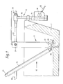
- a conventional casting container or tundish 2 having an outlet nozzle 4 in the bottom wall thereof for directing molten metal from the container 2 into an associated mould.
- the nozzle 4 includes an upper well portion 6 of generally concave form.
- a substantially cylindrical stopper indicated generally at 8 and including a rounded nose end 10 shaped to seat in the well portion 6 of the outlet nozzle 4 to close said nozzle 4.
- the stopper 8 is carried by a mechanism indicated generally at 12 and mounted on a support plate 14 secured to the container 2.
- the mechanism is substantially as described in European patent no. 0084416 and includes a main support shaft 16 mounted to the plate 14 and incorporating a rack with which co-operates a pinion 18 rotatable by means of a handle 20 to raise and lower the shaft 16 relative to the container 2 in conventional manner.
- a transverse arm 22 interconnects the stopper 8 with the shaft 16, one end of the arm 22 carrying a clamp 24 which embraces the upper regions of the stopper 8, while a connecting block indicated generally at 26 secures the other end of the arm 22 to the shaft 16 in such a manner as to permit fore and aft and sideways movement of the arm 22 relative to the block 26 prior to securing the arm 22 to the block.
- the overall arrangement is such as to enable extremely accurate alignment of the nose end 10 of the stopper 8 with the well portion 6 of the nozzle 4 to be achieved.
- a barrier member in the form of a disc 28 located between the nose end 10 of the stopper 8 and the well portion 6 of the outlet nozzle 4.
- the disc 28 is of a flexible high strength paper manufactured from ceramic fibre and marketed under the name KAOWOOL (registered trade mark).
- the inorganic constituents of the material of the disc 28 comprise between 50 and 53% of aluminium oxide (Al2O3) and between 47 and 50% if silicon oxide (Si O2) with 50ppm of leachable chlorides, the material being capable of withstanding continuous temperatures of up to 1260°C.
- the material of the disc 28 includes about 6% organic binder, preferably an acrylic polymer, to give the paper its cold handling strength whilst still retaining its inherent flexibility. This binder will burn out at approximately 300°C without the production of any acidic fumes associated with, for example, neoprene based binder systems as are commonly used in other high strength, high flexibility ceramic fibre papers.
- the disc 28 is positioned over the well portion 6 of the outlet nozzle 4 between the well portion 6 and the nose end 10 of the stopper 8 and, with the stopper 8 in its lowermost operative position closing the nozzle 4, the disc 28 is compressed between the nose end 10 of the stopper 8 and the well portion 6 of the outlet nozzle to constitute a barrier between these components and to seal the nozzle 4 as shown in Fig. 3.
- Discs 28 are used as follows. Subsequent to the first pour of the apparatus using a new stopper 8, and which is effected without a disc 28 between the stopper 8 and the nozzle 4, the container and associated components are inverted with the stopper in its operative closed position to remove the slag that has formed during the casting process.
- the container is then repositioned and the stopper 8 is raised to withdraw the nose end 10 from the well portion 6 and to permit the insertion of a disc 18 between the stopper 8 and the outlet nozzle 4 prior to refilling the container 2 with molten metal.
- the disc 28 is inserted using the applicator indicated generally at 32 which comprises an outer hollow tube 34 having a handle 36 adjacent the upper end thereof and a support plate 38 extending across the lower end thereof and adapted to receive thereon a disc 28.
- a movable rod 40 extends the length of the tube 34 to seat on the plate 38 and to project from the upper end of the tube 34.
- the disc 28 is positioned on the plate 38, the user holding the handle 36 of the applicator 32 with one hand and holding the upper end of the rod 40 with the other hand such as to clamp the disc 28 between the support plate 38 and the lower end of the rod 40.
- the disc 28 is manoeuvred by the user into the position shown in Fig. 1, the rod 40 is moved upwardly to disengage the disc 28 and the applicator 32 is removed to leave the disc 28 across the well portion 6 of the outlet nozzle as shown in Fig. 2.
- the stopper 8 is lowered to its operative position to deform the flexible disc 28 whereby said disc 28 conforms with the shape of the nose end 10 of the stopper 8 and the well-portion 6 of the nozzle 4 as shown in Fig. 3 and thereby seals the outlet nozzle 4 in preparation for the filling of the container 2 with a further batch of molten metal.
- the outer regions 30 of the disc 28 define an annular cup surrounding the lower end of the stopper 8 whereby any slag remaining on the stopper 8 is after inversion of the container 2 and subsequent repositioning thereof and gradually sliding down the stopper 8 received in the outer regions 30 of the disc 28 and is thereby prevented from contaminating the nose end 10 of the stopper 8 and/or the well portion 6 of the nozzle 4.
- the disc 28 provides a barrier member between the stopper 8 and the outlet nozzle 4 to prevent any adhesion of the nose end 10 of the stopper 8 to the well portion 6 of the nozzle 4 and such that subsequent upward movement of the stopper 8 to its inoperative open position can be effected without any damage to the stopper 8 or to the nozzle 4.
- the presence of the disc 28 as a seal between the stopper 8 and the nozzle 4 prevents any leakage past the nose end 10 of the stopper 8 that would otherwise occur if the nose end 10 of the stopper became worn or damaged as can occur on prolonged use of a stopper.
- the apparatus is preheated to about 1000°C in preparation for receiving a further quantity of molten metal, the physical properties of the disc 28 being such that the disc can readily withstand such temperatures.
- the molten metal at a temperature of about 1600°C, is then poured into the container, and the portion 30 of the disc exposed to the molten metal is immediately consumed thereby without the production of any acidic fumes because of the acrylic polymer binder used and whereby the molten metal is not contaminated or its quality impaired.
- the stopper 8 When it is desired to pour the metal, the stopper 8 is raised, there being no resistance to this raising from the lower regions of the stopper 8 because of the presence of the disc 28. On such raising, the remainder of the disc 28 is itself immediately combusted by the molten metal, again without any contamination thereof.
- the above procedure can be repeated using the same stopper providing a barrier member is inserted subsequent to each pour and prior to refilling with molten metal, the presence of the barrier member enabling the apparatus to be left at ambient temperature for extended periods without the stopper adhering to the nozzle as would otherwise occur.
- temperatures associated with metal casting have been considered to provide a relatively unworkable environment not conducive to the introduction of supplementary means to overcome the longstanding problems associated with the casting process.
- the described barrier member eliminates all these problems, and enables a continuous and consistent sequence of pours to be carried out at a much more economic cost than heretofore.
- the disc 28 insulates the stopper 8 from the outlet nozzle 4 whereby the refractory materials of these components stay hotter for longer, giving a better controlled start to the cast because the molten metal has less chance to chill around the nose end 10 of the stopper 8 and the outlet nozzle 4. Additionally, and prior to the provision of a barrier member, the apparatus had to be pre-heated for a considerable length of time to get the slag seal between the nose end 10 of the stopper 8 and the well portion 6 of the outlet nozzle 4 as hot as possible so that the molten metal subsequently poured into the container had a better chance of melting the slag and counteracting the adhesion of the stopper 8 to the outlet nozzle 4 on the first pour through the nozzle.
Landscapes
- Engineering & Computer Science (AREA)
- Mechanical Engineering (AREA)
- Casting Support Devices, Ladles, And Melt Control Thereby (AREA)
- Furnace Charging Or Discharging (AREA)
- Continuous Casting (AREA)
- Manufacture Of Alloys Or Alloy Compounds (AREA)
Applications Claiming Priority (2)
| Application Number | Priority Date | Filing Date | Title |
|---|---|---|---|
| GB898929193A GB8929193D0 (en) | 1989-12-27 | 1989-12-27 | Ceramic fibre joint & applicator |
| GB8929193 | 1989-12-27 |
Publications (3)
| Publication Number | Publication Date |
|---|---|
| EP0435540A2 true EP0435540A2 (de) | 1991-07-03 |
| EP0435540A3 EP0435540A3 (en) | 1992-03-04 |
| EP0435540B1 EP0435540B1 (de) | 1993-09-01 |
Family
ID=10668516
Family Applications (1)
| Application Number | Title | Priority Date | Filing Date |
|---|---|---|---|
| EP90313755A Expired - Lifetime EP0435540B1 (de) | 1989-12-27 | 1990-12-17 | Metallgiessvorrichtung |
Country Status (12)
| Country | Link |
|---|---|
| US (1) | US5164098A (de) |
| EP (1) | EP0435540B1 (de) |
| JP (1) | JPH04270057A (de) |
| KR (1) | KR910011367A (de) |
| CN (1) | CN1053764A (de) |
| AU (1) | AU635373B2 (de) |
| CA (1) | CA2033009C (de) |
| DE (1) | DE69003083T2 (de) |
| ES (1) | ES2047275T3 (de) |
| GB (1) | GB8929193D0 (de) |
| IN (1) | IN179209B (de) |
| ZA (1) | ZA9010411B (de) |
Cited By (1)
| Publication number | Priority date | Publication date | Assignee | Title |
|---|---|---|---|---|
| FR2765316A1 (fr) * | 1997-06-30 | 1998-12-31 | Vesuvius France Sa | Four electrique a trou de coulee excentre et procede d'elaboration d'acier dans ce four |
Families Citing this family (9)
| Publication number | Priority date | Publication date | Assignee | Title |
|---|---|---|---|---|
| GB9418291D0 (en) * | 1994-09-10 | 1994-10-26 | Foseco Int | Improvements in molten metal handling vessels |
| EP0914889A1 (de) * | 1997-10-31 | 1999-05-12 | Elektro-Thermit GmbH | Automatischer Tiegelstöpsel |
| GB2339714B (en) * | 1998-07-16 | 2003-04-02 | Bi Medicast Ltd | High speed casting process and apparatus |
| DE19835087A1 (de) * | 1998-07-24 | 2000-01-27 | Mannesmann Ag | Verfahren und Einrichtung zum schlackefreien Abstechen |
| US8210402B2 (en) * | 2009-02-09 | 2012-07-03 | Ajf, Inc. | Slag control shape device with L-shape loading bracket |
| KR101238891B1 (ko) * | 2010-12-28 | 2013-03-04 | 재단법인 포항산업과학연구원 | 트윈롤 주조 시스템용 노즐 장치 |
| WO2014151094A1 (en) | 2013-03-15 | 2014-09-25 | Rolls-Royce Corporation | Melt infiltration wick attachment |
| WO2014150936A1 (en) | 2013-03-15 | 2014-09-25 | Lazur Andrew J | Melt infiltration apparatus and method for molten metal control |
| CN105710356A (zh) * | 2016-04-29 | 2016-06-29 | 江苏锡华铸造有限公司 | 一种浇铸用定量浇铸系统 |
Citations (1)
| Publication number | Priority date | Publication date | Assignee | Title |
|---|---|---|---|---|
| EP0084416A2 (de) | 1982-01-18 | 1983-07-27 | Stephen David Mills | Halter für Stopfen von Giessgefässen |
Family Cites Families (6)
| Publication number | Priority date | Publication date | Assignee | Title |
|---|---|---|---|---|
| US3124854A (en) * | 1964-03-17 | James | ||
| US2328267A (en) * | 1942-05-18 | 1943-08-31 | Henry G Freeman | Ladle |
| US2883722A (en) * | 1958-11-24 | 1959-04-28 | Bidner John | Method and apparatus for freeing stopper rod in bottom pouring steel ladle |
| US3398945A (en) * | 1965-12-09 | 1968-08-27 | Owens Corning Fiberglass Corp | Molten material furnace hole closures |
| US3540627A (en) * | 1968-03-14 | 1970-11-17 | William V Armstead | Drain seal for metal receptacles |
| GB1201840A (en) * | 1968-05-21 | 1970-08-12 | Foseco Int | Molten metal handling |
-
1989
- 1989-12-27 GB GB898929193A patent/GB8929193D0/en active Pending
-
1990
- 1990-12-17 ES ES90313755T patent/ES2047275T3/es not_active Expired - Lifetime
- 1990-12-17 DE DE90313755T patent/DE69003083T2/de not_active Expired - Fee Related
- 1990-12-17 EP EP90313755A patent/EP0435540B1/de not_active Expired - Lifetime
- 1990-12-20 US US07/631,360 patent/US5164098A/en not_active Expired - Fee Related
- 1990-12-21 CA CA002033009A patent/CA2033009C/en not_active Expired - Fee Related
- 1990-12-21 AU AU68399/90A patent/AU635373B2/en not_active Ceased
- 1990-12-26 IN IN1043MA1990 patent/IN179209B/en unknown
- 1990-12-27 KR KR1019900021991A patent/KR910011367A/ko active IP Right Grant
- 1990-12-27 ZA ZA9010411A patent/ZA9010411B/xx unknown
- 1990-12-27 JP JP2415131A patent/JPH04270057A/ja active Pending
- 1990-12-27 CN CN91100744A patent/CN1053764A/zh active Pending
Patent Citations (1)
| Publication number | Priority date | Publication date | Assignee | Title |
|---|---|---|---|---|
| EP0084416A2 (de) | 1982-01-18 | 1983-07-27 | Stephen David Mills | Halter für Stopfen von Giessgefässen |
Cited By (2)
| Publication number | Priority date | Publication date | Assignee | Title |
|---|---|---|---|---|
| FR2765316A1 (fr) * | 1997-06-30 | 1998-12-31 | Vesuvius France Sa | Four electrique a trou de coulee excentre et procede d'elaboration d'acier dans ce four |
| WO1999001710A1 (en) * | 1997-06-30 | 1999-01-14 | Vesuvius France S.A. | Electric furnace with eccentric taphole and process of steel making in this furnace |
Also Published As
| Publication number | Publication date |
|---|---|
| GB8929193D0 (en) | 1990-02-28 |
| AU6839990A (en) | 1991-07-04 |
| ZA9010411B (en) | 1991-10-30 |
| DE69003083T2 (de) | 1994-02-17 |
| ES2047275T3 (es) | 1994-02-16 |
| CA2033009A1 (en) | 1991-06-28 |
| KR910011367A (ko) | 1991-08-07 |
| CA2033009C (en) | 2001-07-17 |
| EP0435540B1 (de) | 1993-09-01 |
| US5164098A (en) | 1992-11-17 |
| EP0435540A3 (en) | 1992-03-04 |
| DE69003083D1 (de) | 1993-10-07 |
| AU635373B2 (en) | 1993-03-18 |
| IN179209B (de) | 1997-09-13 |
| JPH04270057A (ja) | 1992-09-25 |
| CN1053764A (zh) | 1991-08-14 |
Similar Documents
| Publication | Publication Date | Title |
|---|---|---|
| EP0435540B1 (de) | Metallgiessvorrichtung | |
| TWI417154B (zh) | 熔融金屬用之容器及此種容器之使用以及確定界面層的方法 | |
| EP2399106B1 (de) | Vorrichtung zur temperaturmessung | |
| GB1593371A (en) | Refractory structures | |
| US4640447A (en) | Molten metal immersion pouring spout | |
| TW436524B (en) | Method and device for sealing a tap hole metallurgical containers | |
| EP0314807B1 (de) | Behälter für geschmolzenes metall | |
| JPS61502319A (ja) | セラミツク材の流出口 | |
| CA1151835A (en) | Metallurgical pouring vessels | |
| US4219139A (en) | Bottom pouring crucible | |
| US4138096A (en) | Combined crucible, tundish and pouring spout | |
| CA1315520C (en) | Apparatus for pouring molten steel into a mold in a continuous casting of steel | |
| US5249780A (en) | Slag control shape release apparatus for molten metal vessels | |
| US4854550A (en) | Stopper for retaining slag and process for implementation and manufacture thereof | |
| US4210617A (en) | Method of casting an integral slide gate and nozzle | |
| US4231498A (en) | Corrosion-resistant crucible with graphite parts | |
| CA2018376A1 (en) | Retaining and/or pouring means for tanks for metal melting baths | |
| WO2005059185A1 (en) | Temperature sensing stopper rod | |
| EP1133373B1 (de) | Verbesserungen an oder in bezug auf feuerfestprodukte | |
| EP1287169B1 (de) | Verfahren und vorrichtung zur erzeugung von einer metallurgisch verbesserten metallschmelze | |
| AU695890B2 (en) | Immersed metallurgical pouring nozzles | |
| JP4121048B2 (ja) | 取鍋ノズル充填材の評価方法及び取鍋 | |
| JP2676448B2 (ja) | 銅合金注湯炉の注湯ノズル及び注湯ノズル開閉用ストッパ並びにこれらを用いた注湯口装置 | |
| JP2569878Y2 (ja) | 取鍋ノズルの開口装置 | |
| JP4279392B2 (ja) | 溶融金属鋳造用タンディッシュの羽口周りの熱間補修方法及びそれに用いる熱間補修用容器 |
Legal Events
| Date | Code | Title | Description |
|---|---|---|---|
| PUAI | Public reference made under article 153(3) epc to a published international application that has entered the european phase |
Free format text: ORIGINAL CODE: 0009012 |
|
| AK | Designated contracting states |
Kind code of ref document: A2 Designated state(s): AT BE CH DE DK ES FR GB GR IT LI LU NL SE |
|
| PUAL | Search report despatched |
Free format text: ORIGINAL CODE: 0009013 |
|
| AK | Designated contracting states |
Kind code of ref document: A3 Designated state(s): AT BE CH DE DK ES FR GB GR IT LI LU NL SE |
|
| 17P | Request for examination filed |
Effective date: 19920707 |
|
| 17Q | First examination report despatched |
Effective date: 19921016 |
|
| GRAA | (expected) grant |
Free format text: ORIGINAL CODE: 0009210 |
|
| RBV | Designated contracting states (corrected) |
Designated state(s): DE ES FR GB |
|
| AK | Designated contracting states |
Kind code of ref document: B1 Designated state(s): DE ES FR GB |
|
| REF | Corresponds to: |
Ref document number: 69003083 Country of ref document: DE Date of ref document: 19931007 |
|
| ET | Fr: translation filed | ||
| REG | Reference to a national code |
Ref country code: ES Ref legal event code: FG2A Ref document number: 2047275 Country of ref document: ES Kind code of ref document: T3 |
|
| PLBE | No opposition filed within time limit |
Free format text: ORIGINAL CODE: 0009261 |
|
| STAA | Information on the status of an ep patent application or granted ep patent |
Free format text: STATUS: NO OPPOSITION FILED WITHIN TIME LIMIT |
|
| 26N | No opposition filed | ||
| REG | Reference to a national code |
Ref country code: GB Ref legal event code: 732E |
|
| PGFP | Annual fee paid to national office [announced via postgrant information from national office to epo] |
Ref country code: GB Payment date: 20011207 Year of fee payment: 12 |
|
| PGFP | Annual fee paid to national office [announced via postgrant information from national office to epo] |
Ref country code: ES Payment date: 20011212 Year of fee payment: 12 |
|
| PGFP | Annual fee paid to national office [announced via postgrant information from national office to epo] |
Ref country code: FR Payment date: 20011214 Year of fee payment: 12 |
|
| PGFP | Annual fee paid to national office [announced via postgrant information from national office to epo] |
Ref country code: DE Payment date: 20011224 Year of fee payment: 12 |
|
| REG | Reference to a national code |
Ref country code: GB Ref legal event code: IF02 |
|
| PG25 | Lapsed in a contracting state [announced via postgrant information from national office to epo] |
Ref country code: GB Free format text: LAPSE BECAUSE OF NON-PAYMENT OF DUE FEES Effective date: 20021217 |
|
| PG25 | Lapsed in a contracting state [announced via postgrant information from national office to epo] |
Ref country code: ES Free format text: LAPSE BECAUSE OF NON-PAYMENT OF DUE FEES Effective date: 20021218 |
|
| PG25 | Lapsed in a contracting state [announced via postgrant information from national office to epo] |
Ref country code: DE Free format text: LAPSE BECAUSE OF NON-PAYMENT OF DUE FEES Effective date: 20030701 |
|
| GBPC | Gb: european patent ceased through non-payment of renewal fee |
Effective date: 20021217 |
|
| PG25 | Lapsed in a contracting state [announced via postgrant information from national office to epo] |
Ref country code: FR Free format text: LAPSE BECAUSE OF NON-PAYMENT OF DUE FEES Effective date: 20030901 |
|
| REG | Reference to a national code |
Ref country code: FR Ref legal event code: ST |
|
| REG | Reference to a national code |
Ref country code: ES Ref legal event code: FD2A Effective date: 20021218 |