EP0435441A2 - Vehicle crash barrier with friction brake - Google Patents
Vehicle crash barrier with friction brake Download PDFInfo
- Publication number
- EP0435441A2 EP0435441A2 EP90312525A EP90312525A EP0435441A2 EP 0435441 A2 EP0435441 A2 EP 0435441A2 EP 90312525 A EP90312525 A EP 90312525A EP 90312525 A EP90312525 A EP 90312525A EP 0435441 A2 EP0435441 A2 EP 0435441A2
- Authority
- EP
- European Patent Office
- Prior art keywords
- frame
- vehicle
- crash barrier
- brake
- barrier according
- Prior art date
- Legal status (The legal status is an assumption and is not a legal conclusion. Google has not performed a legal analysis and makes no representation as to the accuracy of the status listed.)
- Granted
Links
Images


Classifications
-
- E—FIXED CONSTRUCTIONS
- E01—CONSTRUCTION OF ROADS, RAILWAYS, OR BRIDGES
- E01F—ADDITIONAL WORK, SUCH AS EQUIPPING ROADS OR THE CONSTRUCTION OF PLATFORMS, HELICOPTER LANDING STAGES, SIGNS, SNOW FENCES, OR THE LIKE
- E01F15/00—Safety arrangements for slowing, redirecting or stopping errant vehicles, e.g. guard posts or bollards; Arrangements for reducing damage to roadside structures due to vehicular impact
- E01F15/14—Safety arrangements for slowing, redirecting or stopping errant vehicles, e.g. guard posts or bollards; Arrangements for reducing damage to roadside structures due to vehicular impact specially adapted for local protection, e.g. for bridge piers, for traffic islands
- E01F15/143—Protecting devices located at the ends of barriers
Definitions
- This invention relates to an improved vehicle crash barrier for decelerating a vehicle that has left a roadway.
- Crash barriers are commonly employed alongside roadways to stop a vehicle that has left the road severelyway in a controlled manner, so as to limit the maximum deceleration to which the occupants of the vehicle are subjected. Additionally, such crash barriers can be struck from the side in a lateral impact, and it is important that the crash barrier have sufficient strength to redirect a laterally impacting vehicle.
- Axially oriented cables are positioned on each side of the diaphragms to maintain the diaphragms in axial alignment during an impact.
- crash barriers are shown in our patents U.S. -B- 3,944,187 and U.S. -B-3,982,734.
- These systems also include a collapsible frame made up of an axially oriented array of diaphragms with side panels mounted to the diaphragms to slide over one another during an axial collapse.
- the barriers of these patents use a cast or molded body of vermiculite or similar material or alternately loosely associated vermiculite particles to perform the energy absorption function.
- Obliquely oriented cables are provided between. the diaphragms and ground anchors to maintain the diaphragms in axial alignment during a lateral impact.
- Our patent U.S. -B- 4,452,431 shows yet another collapsible crash barrier employing diaphragms and side panels generally similar to those described above.
- This system also uses axially oriented cables to maintain the diaphragms in axial alignment, as well as breakaway cables secured between the front diaphragm and the ground anchor. These breakaway cables are provided with shear pins designed to fail during an axial impact to allow the frame to collapse.
- the disclosed crash barrier is used with various types of liquid containing and dry energy absorbing elements.
- U.S. -B- 4,399,980 discloses another similar crash barrier which employs cylindrical tubes oriented axially between adjacent diaphragms. The energy required to deform these tubes during an axial collapse provides a force tending to decelerate the impacting vehicle.
- Cross-braces are used to stiffen the frame against lateral impacts, and a guide is provided for the front of the frame to prevent the front of the frame from moving laterally when the frame is struck in a glancing impact by an impacting vehicle.
- Dragnet System places a net or other restraining structure transversely across a roadway to be blocked.
- the two ends of the net are connected to respective metal ribbons, and these metal ribbons pass through rollers that bend the ribbons as they pay out through the rollers during a vehicle impact.
- the energy required to deform these ribbons results in a kinetic energy dissipating force which decelerates the impacting vehicle.
- the general principle of operation of the metal deforming rollers is shown for example in U.S. -B- 3,211,620 and 3,377,044 as well as U.S. -B- 3,307,832.
- the Dragnet System utilizes the metal ribbons in tension, but it is not well suited for use alongside a roadway because metal bending systems are positioned on both sides of the roadway, and the net or other obstruction extends completely across the roadway.
- a vehicle said crash barrier comprising: an elongated frame comprising a plurality of sections including a front section and at least one additional section arranged end to end along an axial direction, said frame configured to collapse axially when struck axially on the front section by a vehicle; a tension member positioned generally parallel to the frame and having a forward end portion anchored independently of the frame and a rearward end portion; brake means, mounted in the frame, for resiliently biasing a brake member against the tension member to generate a frictional retarding force to decelerate a vehicle as the brake means moves along the tension member during collapse of the frame following impact of the vehicle against the front section.
- the invention provides an elongated frame having a plurality of sections, including a front section and at least one additional section arranged end to end along an axial direction.
- the frame is configured to collapse axially when struck axially on the front section by a vehicle.
- a tension member is positioned generally parallel to the frame and has a forward end portion anchored independently of the frame and a rearward end portion.
- Brake means mounted in the frame resiliently bias a brake member against the tension member to generate a frictional retarding force to decelerate a vehicle as the brake means moves along the tension member during collapse of the frame following impact of the vehicle against the front section.
- the barrier of this invention operates with the tension member in tension rather than compression. This substantially eliminates the need for additional ground anchors and the like which can complicate installation.
- the resiliently biased brake member as described below has been found to provide a retarding force which remains surprisingly constant as the velocity of the brake member varies and it moves along the tension member. Additionally, this retarding force varies surprisingly little, even though the surface of the tension member may be contaminated with dirt, water, ice, and lubricants.
- the brake means includes an abrading material such as aluminum which is used in a friction generating sleeve in contact with the tension member.
- abrading material such as aluminum which is used in a friction generating sleeve in contact with the tension member.
- This approach is believed to be particularly effective in providing a predictable deceleration force under a variety of environmental conditions. Because the sleeve is resiliently biased against the tension member, the sleeve functions properly even after a transient force (such as that created by a protrusion on the tension member) has momentarily forced the sleeve away from the tension member.
- the preferred embodiment described below additionally utilizes means for anchoring the rearward end portion of the tension member and means for coupling the frame to the tension member at a plurality of spaced locations along the frame such that the tension member reenforces the frame against undesired rotation about the axial direction during lateral impacts.
- the embodiment described below employs frame sections, each having a pair of spaced side panels, one on each side of the tension member.
- a plurality of straps are provided, and these straps are secured to the side panels with fasteners such that each strap interconnects a respective pair of axially adjacent side panels.
- the side panels and straps are configured to pull the fasteners out of at least one of the side panels and the straps in response to axial movement of the frame when the vehicle axially impacts the front section, thereby disconnecting the respective axially adjacent sections to allow the frame to collapse axially.
- This aspect of the invention allows the side panels to remain securely fastened together during a lateral impact while still accommodating axial collapse.
- the system described below actually peels the fasteners out of the side panels as the side panels telescope axially.
- This aspect of the invention is not limited to crash barriers having brake means of the type described above. Rather, it can be used broadly in a wide variety of axially collapsing vehicle crash barriers, including the prior art systems discussed above.
- Another important feature of this invention relates to an improved breakaway mechanism disposed at the forward end of the frame.
- the front section of the frame is coupled by at least one fastener to a ground anchor to releasably anchor the front section in place.
- a release member is provided having a first end positioned to be moved by an axially impacting vehicle and a second end coupled to the fastener to release the fastener when the first end is moved by an axially impacting vehicle. This release member is positioned and configured to avoid releasing the fastener when the barrier is struck by a laterally impacting vehicle.
- the release member defines a fulcrum that bears against a reaction surface, and the fulcrum is positioned closer to the second end than the first end such that the axially impacting vehicle pivots the release member about the fulcrum to part the fastener in order to release the front section.
- this aspect of the invention is not limited to crash barriers using brake means as described above, but can also be used with a wide variety of collapsible vehicle crash barriers, including the prior art systems described in the patents identified above.
- bidirectional vehicle crash barriers adapted for use between two adjacent roadways, one carrying vehicles in a first direction and the other carrying vehicles in a second direction, oriented opposite the first direction.
- These bidirectional barriers include a collapsible frame comprising a plurality of sections including a front section, a plurality of middle sections, and a rear section, each of the sections comprising two side panels, each on a respective side of the frame, each side panel having a forward end nearer the front section and a rearward end nearer the rear section.
- the side panels on a first side of the frame overlap with the rearward ends of the side panels disposed outwardly to protect a vehicle moving toward the rear section from contact with the forward ends of the side panels on the first side.
- the side panels on a second side of the frame overlap with the forward ends of the side panels disposed outwardly to protect a vehicle moving toward the front section from contact with the rearward ends of the side panels on the second side.
- the frame includes a means for retarding axial collapse of the frame when the frame is struck by a vehicle axially on the front section to provide a decelerating force to the vehicle.
- This bidirectional barrier operates to redirect a laterally impacting vehicle, whether it strikes the first or second sides of the barrier.
- the pattern of overlapping side panel is reversed on one side of the frame as compared with the other to accommodate the differing directions of traffic movement.
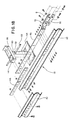
- Figure 1 shows a perspective view of a crash barrier 10 which incorporates the presently preferred embodiment of this inven strictlytion.
- the crash barrier 10 is typically positioned alongside a roadway (not shown) having traffic moving in the direction of the arrow.
- the crash barrier 10 is shown as mounted to the end of a conventional guard rail G, which can be for example of the type having wooden posts P supporting conventional guard rail beams B.
- the crash barrier 10 includes a frame 12 which is axially collapsible and includes a front section 14, three middle sections 16 and a rear section 18.
- the rear section 18 is secured to the guard rail G as described below.
- axial direction means a direction aligned with the length axis of the crash barrier 10, generally parallel to the arrow indicating traffic flow in Figure 1. The following discussion will first describe the frame 12, and then the breakaway assembly, cable assembly, and brake assemblies of the crash barrier 10.
- the front section 14 includes a substantially rigid brake support frame 30.
- This brake support frame 30 includes a pair of horizontal guide members 32 which are oriented axially.
- the horizontal guide members 32 are held fixedly in place by four vertical support members 34 arranged in pairs. Each pair is supported at its top by a cross-brace 36 and its bottom by a base plate 38.
- Each base plate 38 is provided with upwardly oriented edge panels to facilitate sliding of the base plate 38 across the ground without snagging.
- the forward ends of the horizontal guide members 32 are bridged by an end cap 40 which is rigidly secured in place to close off the space between the horizontal guide members 32.
- Two side panels 42 are secured to the forward cross-brace 36 by fasteners 44.
- the rearward ends of the side panels 42 are secured to axially adjacent side panels 42 in the next rearward section by tension straps 46 ( Figure 1), as described in detail below.
- the brake support frame 30 is intended to move across the ground as a substantially rigid framework during at least the initial portion of an axial collapse.
- FIGs 2b and 4 show one of the middle sections 16.
- each of the middle sections 16 includes a vertically oriented leg 50 which defines a pipe grommet 52 centrally located near the upper end of the leg 50.
- the lower end of the leg 50 is secured to a base plate 54 which once again is shaped to facilitate sliding of the base plate 54 across the ground.
- the upper end of the leg 50 is secured to a cross-brace 56 which defines fastener receiving openings 58 ( Figure 17).
- Two side panels 42 are secured to the respective sides of each of the cross-braces 56 by fasteners 44.
- FIG 17 shows the manner in which axially adjacent side panels 42 are interconnected by means of a tension strap 46.
- Each tension strap 46 defines two sets of four openings. The four openings near the front of the tension strap 46 are secured by fasteners 44 to the rearward end of a first side panel 42. The four openings near the rear of the tension strap 46 are secured to the forward end of a second side panel 42. Additionally, two of the fasteners secured to the forward end of the second side panel 42 are fastened to the openings 58 in order to secure the side panel 42 to the cross-brace 56.
- Each of the fasteners 44 comprises an outwardly facing hex head 45 and an inwardly facing threaded nut 47.
- each of the tension straps 46 is preferably a flexible strap made up of a lamination of four separate plates secured together at each end by a rivet 48 ( Figures 15 and 16). As discussed below, by making the tension straps 46 flexible, the frame 12 is allowed to collapse axially in a controlled manner, while still retaining significant strength to withstand lateral impacts.
- Figure 18 shows an exploded perspective view of the rear section 18 which is secured to a transition strap 70.
- the transition strap 70 is in turn secured by fasteners and plates 72 to the forward-most end of the beam B of the guardrail.
- a front anchor assembly 80 is provided, as shown in Figures 6-8.
- This front anchor assembly 80 includes a concrete pile 82.
- a box structure 84 of reinforcing bars is anchored in the pile 82, and the upper end of this box structure 84 supports two C channels 86.
- Three tubes including a larger central tube 88 and a pair of smaller side tubes 90 are rigidly secured, as for example by welding, between the C channels 86.
- the tubes 88, 90 are oriented axially and tilted slightly such that the front ends are lower than the rearward ends.
- the side tubes 90 are used to secure the front section 14 to the front anchor assembly 80 by means of bolts 92. These bolts 92 are secured at their rearward ends to an angle 94 rigidly mounted on the front vertical support members 34 of the brake support frame 30 ( Figure 9). These bolts 92 pass through the side tubes 90 and are held in place by nuts 93 ( Figures 7 and 8).
- the front anchor assembly 80 serves to anchor the front end of the frame 12 when the frame 12 is struck laterally by an impacting vehicle moving obliquely with respect to the axial direction.
- This breakaway assembly 100 includes a lever arm 102 which terminates at its lower end in a pair of tubes 104. Each of the tubes 104 defines a fulcrum 106 adjacent its upper edge where it bears against a reaction surface formed by the respective side tube 90. As shown in Figure 8, the lever arm 102 is generally V-shaped, and a C-shaped guide 108 is provided to guide the lever arm 102 as it moves axially along the wire cable during collapse of the frame 12.
- the upper end of the lever arm 102 is rigidly secured to a plate 112, which is in turn secured by fasteners to a nose plate 114.
- the nose plate 114 is generally C-shaped, and is secured by fasteners at its rearward edges to the front cross-brace 36 of the brake support frame 30.
- the lever arm 102 is oriented obliquely with respect to the vertical direction, with its upper end positioned forwardly of its lower end.
- the impacting vehicle contacts the nose plate 114 and pushes the plate 112 rearwardly. This pivots the lever arm 102 about the fulcrum 106, providing a large elongating force which parts the bolts 92.
- the brake support frame 30 is released from the front anchor assembly 80, and the frame 12 is free to collapse axially as it decelerates the impacting vehicle.
- breakaway assembly 100 responds preferentially to an axial impacting force to part the bolts 92. If the nose plate 114 is struck at a large oblique angle, or if the frame 12 is struck obliquely along its length, the lever arm 102 does not pivot around the fulcrum 106, and the breakaway assembly 100 does not function as described above. This direction specific characteristic of the breakaway assembly 100 provides important advantages.
- FIG 10 provides a view of a cable assembly 120 included in the crash barrier 10.
- This cable assembly 120 includes a tension member such as a wire cable 122 that is provided with threaded bolts 124, 128 at its forward and rearward ends.
- the forward bolt 124 passes through the central tube 88 of the front anchor assembly 80 and is secured in place by a nut 125, as shown in Figure 8.
- the rear bolt 128 passes through an opening in one of the posts P, and is likewise secured in place by a nut ( Figure 2c).
- a plate washer 126 is provided to spread the tension forces of the wire cable 122 on the post P.
- the wire cable 122 passes through the grommets 52 of the legs 50.
- a sliding stop 130 is mounted on the wire cable 122.
- This sliding stop 130 includes a central tube 132 interposed between two flanges 134.
- the flanges 134 are received within the horizontal guide members 32 such that the sliding stop 130 is slidable along the length of the brake support frame 30 ( Figure 2a).
- a sleeve of low friction material 136 (Figure 11) is applied to the wire cable 122 for a short distance near the rearward end of the horizontal guide members 32, for reasons described below. Additionally, this low friction material 136 can be lubricated with a lubricant 138.
- the crash barrier 10 includes two brake assemblies 140, best shown in Figures 11-13.
- the brake assemblies 140 each include a pair of brake sleeves 142 shaped to fit around and engage the wire cable 122.
- the brake sleeves are preferably made of an abradable material such as aluminum.
- the sleeves 142 are positioned inside respective sleeve clamps 144 which include retaining shoulders 145 positioned to prevent the sleeves 142 from moving axially out of the sleeve clamps 144.
- a pair of spring plates 146 are provided on each side of the brake assembly 140, and these spring plates 146 are separated at their periphery by a spacer ring 148 ( Figures 13 and 14).
- a pair of guides 150 made of C section channels are mounted at the sides of each brake assembly 40.
- the two brake assemblies 140 are mounted in the horizontal guide members 32 of the brake support frame 30, with the guides 150 allowing the brake assemblies 140 to move axially along the horizontal guide members 32.
- the sliding stop 130 is positioned on the wire cable 122 forward of the brake assemblies 140, and a tubular spacer 156 is positioned around the wire cable 122 between the brake assemblies 140 to bear on the sleeve clamps 144.
- the brake assemblies 140 Prior to impact, the brake assemblies 140 are positioned near the rearward end of the horizontal guide members 32, with the brake sleeves 142 of both of the brake assemblies 140 engaging the low friction material 136 on the wire cable 122 ( Figure 2a).
- the pile 82 is two feet in diameter and five feet in depth and the bolts 92 are 7/8 inch diameter grade B threaded rods.
- the wire cable 122 in this embodiment is a 1 inch diameter 6 by 25 galvanized cable.
- the horizontal guide members 32 in this embodiment are 6 feet in length. This length provides control over objectionable rotational forces imposed by a car striking the crash barrier 10 obliquely.
- the brake support frame 30 provides protection for the brake assemblies 140 such that they are never struck by the vehicle.
- the legs 50 are spaced on six foot, three inch centers.
- the brake sleeves 142 can be made of aluminum alloy #6061-T6, which has been found to provide a high coefficient of friction and to provide an abrading surface so that hydrodynamic skating will not develop.
- the spring plates 146 are made of high strength steel such as AR400 plate, and are in this embodiment 3/8 inch thick and 101 ⁇ 4 inch in diameter.
- the spring plates 146 are highly stressed, and should preferably be made of a material with a yield strength greater than 165,000 psi.
- the holes in the spring plates 146 are preferably drilled (not punched) and countersunk to reduce microfractures.
- the spring plates 146 preferably apply a resilient force of about 50,000 pounds biasing each sleeve 142 against the cable 122.
- the sleeves 142 are preferably 71 ⁇ 2 inches in length.
- the tension straps 46 are laminated from 14 gauge A-591 galvanized A-526 sheet steel, and the openings in the straps freely receive a standard 5/8 inch diameter galvanized bolt.
- the fasteners 44 used to secure the straps 46 to the side panels 42 are preferably 5/8 inch diameter bolts with standard hex heads 45 (without washers) positioned to the outside and standard hex nuts 47 (11/16 inch high and 11 ⁇ 4 inch between parallel faces, ASTM-A563, Central Fence Co., Sacramento, Ca.).
- the side panels 42 can be formed from 12 gauge cold rolled steel with punched 11/16 inch holes, and are preferably hot dip galvanized after fabrication per ASTM A-123. Knock outs may be provided in the side panels 42 at each end of each set of four holes to allow the fasteners 44 to be placed in any of three positions. In this way the effective length of the side panels 42 may be selected to suit the application.
- the horizontal guide members 32 are configured such that the brake assemblies 140 can move approximately 50 inches towards the front of the brake support frame 30 before the sliding stop 130 contacts the end plate 40.
- the low friction material 136 is preferably made from a sleeve of zinc or urethane plastic.
- the high pressure lubricant 138 can for example be graphite, molydisulfide or powdered metal.
- the openings in the tension straps 46 are precisely positioned to ensure that the four fasteners share the load and develop a 60,000 pound maximum tension.
- the flexibility of the tension straps 46 ensures that a relatively low force of about 5000 pounds is required to release the fasteners 44 from the tension straps 46 as described below.
- the brake assemblies 140 are positioned near the rearward end of the horizontal guide members 32, with the brake sleeves 142 on the low friction material 136 and the lubricant 138.
- the breakaway assembly 100 functions as described above to release the front section 14 from the front anchor assembly 80.
- the brake support frame 30 moves rearwardly, and the brake assemblies 140 remain in position on the wire cable 122.
- the sliding stop 130 comes into contact with the end cap 40, thereby transmitting rearwardly directed forces to the brake assemblies 140. This causes the brake assemblies 140 to begin to slide along the wire cable 122.
- the sliding stop 130 is shaped to bear directly on the sleeve clamps 142 of the forward brake assembly 140, and the sleeve clamps 142 of the forward brake assembly 140 transmit axial forces via the tubular spacer 156 directly to the sleeve clamps 142 of the rear brake assembly 140 ( Figure 13).
- This arrangement ensures that axial forces are applied to the brake assemblies 140 very near to the cable 122, and thereby minimizes any tendency of the brake assemblies to rotate with respect to the cable 122.
- the sliding stop 130 and the brake assemblies 140 are free to float a slight amount in the guide members 32, thereby further reducing any rotational torques applied to the brake assemblies 140.
- the low friction material 136 and the lubricant 138 cooperate to reduce the static coefficient of friction and to prevent the brake assemblies 140 from developing excessive retarding forces as they begin to slide along the wire cable 122.
- the brake support frame 30 has a substantial mass, and the inertial forces required to accelerate the brake support frame 30 provide a substantial initial retarding force on the vehicle.
- the brake assemblies 140 do not contribute to the retarding force until after the brake support frame 30 has been substantially accelerated. This results in a lower peak decelerating force on the vehicle.
- the low friction material 136 and the lubricant 138 further reduce deceleration peaks associated with initial movement of the brake assemblies 140.
- the brake assemblies 140 are caused to slide along the length of the wire cable 122, and the brake sleeves 142 provide a large retarding force on the vehicle.
- FIGs 19a-19c show the manner in which the tension straps 46 allow axially adjacent side panels 42 to disengage from one another during the axial collapse of the frame 12.
- the side panels 42 are initially arranged in a fish scale pattern with the rearward ends of the side panels 42 disposed outwardly.
- the tension straps 46 are initially provided with a slight S shape. As axial forces on a side panel 42 increase, it tends to move rearwardly as shown in Figure 19b, bending the tension strap 46 into a pronounced S shaped curve.
- the tension straps 46 are made up of a lamination of individual plates to provide increased flexibility to encourage this effect.
- the tension strap 46 assumes the position shown in Figure 19b, where substantial peeling forces are applied to an individual one of the fasteners 44.
- the fasteners 44 are provided without washers at their outer ends, and the heads 45 of the fasteners 44 peel through the side panel 42 one by one, as shown in Figure 19c. In this way, the entire frame 12 can collapse axially in order to allow the brake assembly 140 to move along the wire cable 122.
- the resiliently biased brake means described above have been found to provide a surprisingly constant retarding force in spite of variations in position and velocity of the brake means along the wire cable, and in spite of wide variations in the surface condition of the wire cable 122.
- the total stroke of the brake means is about 20 feet, and the retarding force supplied by the brake means is surprisingly constant at about 11,000 pounds.
- the spring plates 146 move to maintain the brake sleeves 142 in resilient contact with the wire cable 122, even as the brake sleeves 142 change in dimension as aluminum is abraded.
- the retarding force remains substantially constant throughout the stroke. This is believed to be associated with the increasing temperature of the brake sleeves 142 resulting from frictional heating.
- the retarding force generated by the braking means has been found to vary little, even in the face of wide variations in the velocity of movement of the braking means along the cable.
- the retarding force generated by the braking means has been found to vary surprisingly little in spite of wide variations in the surface condition of the wire cable. Water, dirt, and even lubricants on the wire cable do not have a major effect on the retarding force after the braking means is moving along the wire cable.
- the braking sleeve should be formed of a suitable material.
- the material should provide a high coefficient of friction, should be selected so as not to weld to the cable when heated, and not to work harden substantially during use so as to reduce friction.
- Aluminum alloys are preferred, and aluminum alloy #6061-T6 has been found particularly well suited for use in this embodiment.
- the crash barrier 10 functions quite differ strictlyently in a lateral impact.
- the breakaway assembly 100 does not release the front section 14 from the front anchor assembly 80.
- the tension straps 46 operate in tension, and do not peel away the fasteners 44 as described above.
- the side panels 42 are anchored at both their forward and rearward ends, and are able to support substantial compressive and tensile forces.
- the wire cable 122 is anchored at its forward end to the front anchor assembly 80 and at its rearward end to the guard rail G.
- the wire cable 122 passes through the grommets 52 to support the legs 50 against lateral movement and rotation.
- the wire cable 122, the side panels 42, and the tension straps 46 insure that the crash barrier 10 has substantial lateral rigidity.
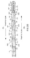
- FIG 20 shows a bidirectional crash barrier 200 which incorporates a presently preferred embodiment of this invention.
- This bidirectional barrier 200 is shown mounted between two parallel roadways R1, R2. Each roadway carries traffic moving in the direction of the arrows.
- the bidirectional barrier 200 is shown mounted to the end of a guardrail G, which may be identical to that described above.
- the barrier 200 includes a collapsible frame 202 which is made up of a front section 204, several middle sections 206 and a rear section 208.
- the rear section 208 is secured to the end of the guardrail G.
- the frame 202 is made of the same components as those described above.
- the front section 204 includes a brake support frame 210 which is identical to the brake support frame 30 described above.
- the brake support frame 210 supports a plurality of brake assemblies 212 identical to the assemblies 140 described above.
- the brake assemblies 212 are designed to slide along a wire cable 214 as described above.
- each of the sections 204, 206, 208 has two sides, and a side panel 216 is mounted on each side of each section 204, 206, 208.
- Axially adjacent ones of the side panels 216 in this embodiment are connected together with tension straps 218 in the same manner as that described above.
- the overlapping of the side panels 216 differs between the two sides of the frame 202.
- the side panels 216 are arranged in the same configuration as the embodiment of Fig. 1.
- the pattern of overlapping is reversed.
- the rearward ends of the side panels 216 are disposed inwardly (nearer the wire cable 214) and the forward ends of the side panels 216 are disposed outwardly (nearer the roadway R2).
- This arrangement ensures that vehicles travelling in the direction of the arrow on roadway R2 and striking the side panels 216 in a glancing blow are free to slide along the side panels 216 on the side of the frame 202 adjacent the roadway R2, protected from the rearward, inwardly disposed ends of the side panels 216.
- vehicles travelling along the direction of the arrow on the roadway R1 are also free to slide along the side panels 216 on the side of the frame 202 adjacent the roadway R1, and are protected from undesirable contact with the forward ends of the side panels 216.
- the axial rigidity of the brake support frame 210 in the front section 204 protects such a vehicle from being speared by one of the side panels 216 on the side of the frame 202 adjacent the roadway R2.
- the middle sections 206 collapse, the forward ends of the side panels 216 on the side of the frame 202 adjacent the roadway R2 approach the impacting vehicle.
- the substantially rigid brake support frame 210 acts as a spacer, preventing the impacting vehicle from contacting and being speared by the forward ends of the side panels 216.
- the brake support frame 210 acts as a brace against axial collapse of the front section 204 and ensures that the front section 204 is more resistant to axial collapse than the middle sections 206.
- the design described above provides a front section 204 which is sufficiently resistant to axial collapse so as not to collapse in operation when struck by a vehicle of the maximum design weight travelling at the maximum design speed of the barrier 200.
- the asymmetrical orientation of the side panel 216 causes the two sides of the frame 202 to collapse in a somewhat different manner.
- the side panels 216 on the upper side of the frame 202 in Figure 20 do not telescope with respect to one another between the front section 204 and the immediately adjacent middle section 206.
- telescoping movement is accommodated between the side panels 216 on the lower side of Figure 20 between these two sections 204, 206.
- the side panel 216 on the upper side of Figure 20 that is secured to the guardrail G is secured by means of a tension strap 218 of the type described above, to permit telescoping therebetween.
- the side panel 216 on the lower portion of the rear section 208 (as shown in Figure 20) is fixedly secured to the second side of the guardrail G, to prevent any telescoping.
- the asymmetrical telescoping action at the front and rear ends of the collapsible frame 202 offset one another to provide an improved pattern of telescoping.
- the bidirectional barrier of this invention can be implemented with a variety of approaches other than those described above.
- frictional braking means are not required to create a retarding force for the axially impacting vehicle.
- any of the prior art approaches described in the patents discussed above can be substituted, including systems using a plurality of energy absorbing members positioned in the frame to retard axial collapse of the frame as a result of compressive deformation of the energy absorbing members.
- the foam filled hexagonal lattices described in U.S. -B- 4,352,484 or the deformable tubes shown in U.S. -B- 4,399,980 can be used in substitution for the frictional braking means shown in Figure 20.
- a bidirectional barrier 200 which performs three separate functions. First, it collapses axially to retard an axially impacting vehicle striking the front section 204. Second, it redirects a vehicle travelling on the roadway R1 which strikes the barrier 200 laterally along its length, without spearing the vehicle. Third, it redirects a vehicle travelling on the roadway R2 which strikes the barrier 200 laterally, again without spearing the vehicle.
- the breakaway assembly 100 and the tension straps 46 described above can be used with more conventional crash barriers which do not rely on friction brakes such as the brake assemblies 140.
- the brake assembly 140 can be modified to use a wide variety of braking means and biasing means, including other types of springs and hydraulic biasing arrangements.
- dimensions, proportions and shapes can all be modified to suit the intended application.
Abstract

Description
- This invention relates to an improved vehicle crash barrier for decelerating a vehicle that has left a roadway.
- Crash barriers are commonly employed alongside roadways to stop a vehicle that has left the roadway in a controlled manner, so as to limit the maximum deceleration to which the occupants of the vehicle are subjected. Additionally, such crash barriers can be struck from the side in a lateral impact, and it is important that the crash barrier have sufficient strength to redirect a laterally impacting vehicle.
- A number of prior art approaches have been suggested for such crash barriers employing an axially collapsible frame having compression resistant elements disposed one behind the other in the frame. Our patent U.S. -B- 3,674,115 provides an early example of one such system. This system includes a frame made up of an axially oriented array of segments, each having a diaphragm extending transverse to the axial direction and a pair of side panels positioned to extend rearwardly from the diaphragm. Energy absorbing elements (in this example water filled flexible cylindrical elements) are mounted between the diaphragms. During an axial impact the diaphragms deform the energy absorbing elements, thereby causing water to be accelerated to absorb the kinetic energy of the impacting vehicle. Axially oriented cables are positioned on each side of the diaphragms to maintain the diaphragms in axial alignment during an impact.
- Other examples of such crash barriers are shown in our patents U.S. -B- 3,944,187 and U.S. -B-3,982,734. These systems also include a collapsible frame made up of an axially oriented array of diaphragms with side panels mounted to the diaphragms to slide over one another during an axial collapse. The barriers of these patents use a cast or molded body of vermiculite or similar material or alternately loosely associated vermiculite particles to perform the energy absorption function. Obliquely oriented cables are provided between. the diaphragms and ground anchors to maintain the diaphragms in axial alignment during a lateral impact.
- Our patent U.S. -B- 4,352,484 discloses an improved crash barrier that utilizes an energy absorbing cartridge made up of foam filled hexagonal lattices arranged to shear into one another in response to the compression forces applied to the energy absorbing cartridge by an impacting vehicle.
- Our patent U.S. -B- 4,452,431, shows yet another collapsible crash barrier employing diaphragms and side panels generally similar to those described above. This system also uses axially oriented cables to maintain the diaphragms in axial alignment, as well as breakaway cables secured between the front diaphragm and the ground anchor. These breakaway cables are provided with shear pins designed to fail during an axial impact to allow the frame to collapse. The disclosed crash barrier is used with various types of liquid containing and dry energy absorbing elements.
- U.S. -B- 4,399,980 discloses another similar crash barrier which employs cylindrical tubes oriented axially between adjacent diaphragms. The energy required to deform these tubes during an axial collapse provides a force tending to decelerate the impacting vehicle. Cross-braces are used to stiffen the frame against lateral impacts, and a guide is provided for the front of the frame to prevent the front of the frame from moving laterally when the frame is struck in a glancing impact by an impacting vehicle.
- All of these prior art systems are designed to absorb the kinetic energy of the impacting vehicle by compressively deforming an energy absorbing structure. Because of the potential instability of compressive deformation, these systems use structural members to resist side forces that develop from compression loading. Furthermore, all use sliding side panels designed to telescope past one another during an impact. Because such sliding side panels must slide past one another during an axial impact, they have a limited strength in compression. This can be a disadvantage in some applications.
- Another prior art system known as the Dragnet System places a net or other restraining structure transversely across a roadway to be blocked. The two ends of the net are connected to respective metal ribbons, and these metal ribbons pass through rollers that bend the ribbons as they pay out through the rollers during a vehicle impact. The energy required to deform these ribbons results in a kinetic energy dissipating force which decelerates the impacting vehicle. The general principle of operation of the metal deforming rollers is shown for example in U.S. -B- 3,211,620 and 3,377,044 as well as U.S. -B- 3,307,832. The Dragnet System utilizes the metal ribbons in tension, but it is not well suited for use alongside a roadway because metal bending systems are positioned on both sides of the roadway, and the net or other obstruction extends completely across the roadway.
- Our patent U.S. -B- 4,784,515 describes a collapsible guard rail end terminal that utilizes a wire cable extending through grommets in legs of the end terminal. The side panels of the end terminal are mounted to slide over one another when struck axially. When the end terminal collapses during an impact, the legs may be rotated such that the grommets work the cable and create a frictional force on the cable. However, the magnitude of the resulting retarding forces is highly variable, due to the variable and unpredictable rotational positions of the legs during the collapse.
- Thus, a need presently exists for an improved highway crash barrier that provides predictable decelerating forces to an axially impacting vehicle, that is low in cost, that is simple to install, that utilize a minimum of cross-bracing of the type required in the past to resist lateral impacts, and that efficiently redirects laterally impacting vehicles.
- According to the invention there is provided a vehicle, said crash barrier comprising:
an elongated frame comprising a plurality of sections including a front section and at least one additional section arranged end to end along an axial direction, said frame configured to collapse axially when struck axially on the front section by a vehicle;
a tension member positioned generally parallel to the frame and having a forward end portion anchored independently of the frame and a rearward end portion;
brake means, mounted in the frame, for resiliently biasing a brake member against the tension member to generate a frictional retarding force to decelerate a vehicle as the brake means moves along the tension member during collapse of the frame following impact of the vehicle against the front section. Thus the invention provides an elongated frame having a plurality of sections, including a front section and at least one additional section arranged end to end along an axial direction. The frame is configured to collapse axially when struck axially on the front section by a vehicle. A tension member is positioned generally parallel to the frame and has a forward end portion anchored independently of the frame and a rearward end portion. Brake means mounted in the frame, resiliently bias a brake member against the tension member to generate a frictional retarding force to decelerate a vehicle as the brake means moves along the tension member during collapse of the frame following impact of the vehicle against the front section. - Because the retarding force is provided by the interaction between the brake means and the tension member and the tension member is anchored at its forward end portion, the barrier of this invention operates with the tension member in tension rather than compression. This substantially eliminates the need for additional ground anchors and the like which can complicate installation. The resiliently biased brake member as described below has been found to provide a retarding force which remains surprisingly constant as the velocity of the brake member varies and it moves along the tension member. Additionally, this retarding force varies surprisingly little, even though the surface of the tension member may be contaminated with dirt, water, ice, and lubricants.
- In this embodiment, the brake means includes an abrading material such as aluminum which is used in a friction generating sleeve in contact with the tension member. This approach is believed to be particularly effective in providing a predictable deceleration force under a variety of environmental conditions. Because the sleeve is resiliently biased against the tension member, the sleeve functions properly even after a transient force (such as that created by a protrusion on the tension member) has momentarily forced the sleeve away from the tension member.
- In order to provide a crash barrier that is particularly effective against lateral impacts, the preferred embodiment described below additionally utilizes means for anchoring the rearward end portion of the tension member and means for coupling the frame to the tension member at a plurality of spaced locations along the frame such that the tension member reenforces the frame against undesired rotation about the axial direction during lateral impacts.
- The embodiment described below employs frame sections, each having a pair of spaced side panels, one on each side of the tension member. A plurality of straps are provided, and these straps are secured to the side panels with fasteners such that each strap interconnects a respective pair of axially adjacent side panels. The side panels and straps are configured to pull the fasteners out of at least one of the side panels and the straps in response to axial movement of the frame when the vehicle axially impacts the front section, thereby disconnecting the respective axially adjacent sections to allow the frame to collapse axially.
- This aspect of the invention allows the side panels to remain securely fastened together during a lateral impact while still accommodating axial collapse. The system described below actually peels the fasteners out of the side panels as the side panels telescope axially. This aspect of the invention is not limited to crash barriers having brake means of the type described above. Rather, it can be used broadly in a wide variety of axially collapsing vehicle crash barriers, including the prior art systems discussed above.
- Another important feature of this invention relates to an improved breakaway mechanism disposed at the forward end of the frame. The front section of the frame is coupled by at least one fastener to a ground anchor to releasably anchor the front section in place. A release member is provided having a first end positioned to be moved by an axially impacting vehicle and a second end coupled to the fastener to release the fastener when the first end is moved by an axially impacting vehicle. This release member is positioned and configured to avoid releasing the fastener when the barrier is struck by a laterally impacting vehicle. Preferably, the release member defines a fulcrum that bears against a reaction surface, and the fulcrum is positioned closer to the second end than the first end such that the axially impacting vehicle pivots the release member about the fulcrum to part the fastener in order to release the front section. Once again, this aspect of the invention is not limited to crash barriers using brake means as described above, but can also be used with a wide variety of collapsible vehicle crash barriers, including the prior art systems described in the patents identified above.
- Certain embodiments described below are bidirectional vehicle crash barriers adapted for use between two adjacent roadways, one carrying vehicles in a first direction and the other carrying vehicles in a second direction, oriented opposite the first direction. These bidirectional barriers include a collapsible frame comprising a plurality of sections including a front section, a plurality of middle sections, and a rear section, each of the sections comprising two side panels, each on a respective side of the frame, each side panel having a forward end nearer the front section and a rearward end nearer the rear section. The side panels on a first side of the frame overlap with the rearward ends of the side panels disposed outwardly to protect a vehicle moving toward the rear section from contact with the forward ends of the side panels on the first side. The side panels on a second side of the frame overlap with the forward ends of the side panels disposed outwardly to protect a vehicle moving toward the front section from contact with the rearward ends of the side panels on the second side. The frame includes a means for retarding axial collapse of the frame when the frame is struck by a vehicle axially on the front section to provide a decelerating force to the vehicle.
- This bidirectional barrier operates to redirect a laterally impacting vehicle, whether it strikes the first or second sides of the barrier. The pattern of overlapping side panel is reversed on one side of the frame as compared with the other to accommodate the differing directions of traffic movement. These advantages are obtained without interfering with the ability of the frame to collapse on axial impact and to provide a decelerating force for a vehicle striking the front section. This aspect of the invention is not limited to use with the breaking means, the side panel securing means, or the breakaway mechanism described above. Rather, this aspect of the invention can readily be adapted for use with a wide range of prior art crash barriers, such as those described in the prior art patents discussed above.
- There now follows a descrption of specific embodiments of the invention, by way of example, with reference being made to the accompanying drawings in which:
- Figure 1 is a perspective view of a vehicle crash barrier which incorporates the presently preferred embodiment of this invention.
- Figures 2a, 2b and 2c are side elevational views of front, middle and rearward portions of the barrier of FIG. 1.
- Figure 3 is a cross-sectional view taken along line 3-3 of FIG. 2a.
- Figure 4 is a cross-sectional view taken along line 4-4 of FIG. 2b.
- Figure 5 is a cross-sectional view taken along line 5-5 of FIG. 2c.
- Figure 6 is a top plan view of a front portion of the barrier of FIG. 1.
- Figure 7 is a cross-sectional view taken along line 7-7 of FIG. 6.
- Figure 8 is an exploded perspective view of selected elements shown in FIG. 7.
- Figure 9 is a fragmentary perspective view in partial cutaway of additional elements shown in FIG. 7.
- Figure 10 is a perspective view of a wire cable, associated brake assemblies, and related elements of the barrier of FIG. 1.
- Figure 11 is an exploded perspective view of selected portions of one of the brake assemblies of FIG. 10.
- Figure 12 is an exploded cross-sectional view of selected elements of FIG. 11.
- Figure 13 is a cross-sectional view taken along line 13-13 of FIG. 14.
- Figure 14 is a cross-sectional view of one of the brake assemblies of FIG. 10, taken along line 14-14 of FIG. 13.
- Figure 15 is a plan view of one of the tension straps of the embodiment of FIG. 1.
- Figure 16 is a partial sectional view taken along line 16-16 of FIG. 15.
- Figure 17 is an exploded perspective view of portions of one of the middle sections of FIG. 1.
- Figure 18 is an exploded perspective view of portions of the rear section of FIG. 1.
- Figures 19a-19c are schematic views showing three stages in the axial collapse of the crash barrier of FIG. 1.
- Figure 20 is a schematic top view showing a bidirectional vehicle crash barrier which is formed of the components shown in the preceding figures.
- Turning now to the drawings, Figure 1 shows a perspective view of a
crash barrier 10 which incorporates the presently preferred embodiment of this invention. Thecrash barrier 10 is typically positioned alongside a roadway (not shown) having traffic moving in the direction of the arrow. Thecrash barrier 10 is shown as mounted to the end of a conventional guard rail G, which can be for example of the type having wooden posts P supporting conventional guard rail beams B. As shown in Figure 1, thecrash barrier 10 includes aframe 12 which is axially collapsible and includes afront section 14, threemiddle sections 16 and arear section 18. Therear section 18 is secured to the guard rail G as described below. As used herein the term "axial direction" means a direction aligned with the length axis of thecrash barrier 10, generally parallel to the arrow indicating traffic flow in Figure 1. The following discussion will first describe theframe 12, and then the breakaway assembly, cable assembly, and brake assemblies of thecrash barrier 10. - Turning to Figures 2 and 3, the
front section 14 includes a substantially rigidbrake support frame 30. Thisbrake support frame 30 includes a pair ofhorizontal guide members 32 which are oriented axially. Thehorizontal guide members 32 are held fixedly in place by fourvertical support members 34 arranged in pairs. Each pair is supported at its top by across-brace 36 and its bottom by abase plate 38. Eachbase plate 38 is provided with upwardly oriented edge panels to facilitate sliding of thebase plate 38 across the ground without snagging. The forward ends of thehorizontal guide members 32 are bridged by anend cap 40 which is rigidly secured in place to close off the space between thehorizontal guide members 32. Twoside panels 42 are secured to theforward cross-brace 36 byfasteners 44. The rearward ends of theside panels 42 are secured to axiallyadjacent side panels 42 in the next rearward section by tension straps 46 (Figure 1), as described in detail below. Thebrake support frame 30 is intended to move across the ground as a substantially rigid framework during at least the initial portion of an axial collapse. - Figures 2b and 4 show one of the
middle sections 16. As shown in Figure 4, each of themiddle sections 16 includes a vertically orientedleg 50 which defines apipe grommet 52 centrally located near the upper end of theleg 50. The lower end of theleg 50 is secured to abase plate 54 which once again is shaped to facilitate sliding of thebase plate 54 across the ground. The upper end of theleg 50 is secured to a cross-brace 56 which defines fastener receiving openings 58 (Figure 17). Twoside panels 42 are secured to the respective sides of each of the cross-braces 56 byfasteners 44. - Figure 17 shows the manner in which axially
adjacent side panels 42 are interconnected by means of atension strap 46. Eachtension strap 46 defines two sets of four openings. The four openings near the front of thetension strap 46 are secured byfasteners 44 to the rearward end of afirst side panel 42. The four openings near the rear of thetension strap 46 are secured to the forward end of asecond side panel 42. Additionally, two of the fasteners secured to the forward end of thesecond side panel 42 are fastened to theopenings 58 in order to secure theside panel 42 to thecross-brace 56. Each of thefasteners 44 comprises an outwardly facinghex head 45 and an inwardly facing threadednut 47. - For reasons discussed in detail below, each of the tension straps 46 is preferably a flexible strap made up of a lamination of four separate plates secured together at each end by a rivet 48 (Figures 15 and 16). As discussed below, by making the tension straps 46 flexible, the
frame 12 is allowed to collapse axially in a controlled manner, while still retaining significant strength to withstand lateral impacts. - Figure 18 shows an exploded perspective view of the
rear section 18 which is secured to atransition strap 70. Thetransition strap 70 is in turn secured by fasteners andplates 72 to the forward-most end of the beam B of the guardrail. - The
frame 12 described above is not secured to the ground in any way, and is simply secured to the guard rail G by thetransition strap 70 andplates 72. In order to position thefront section 14 properly, afront anchor assembly 80 is provided, as shown in Figures 6-8. Thisfront anchor assembly 80 includes aconcrete pile 82. Abox structure 84 of reinforcing bars is anchored in thepile 82, and the upper end of thisbox structure 84 supports twoC channels 86. Three tubes including a largercentral tube 88 and a pair ofsmaller side tubes 90 are rigidly secured, as for example by welding, between theC channels 86. As shown in Figure 8, thetubes - As shown in Figures 6 and 8, the
side tubes 90 are used to secure thefront section 14 to thefront anchor assembly 80 by means ofbolts 92. Thesebolts 92 are secured at their rearward ends to anangle 94 rigidly mounted on the frontvertical support members 34 of the brake support frame 30 (Figure 9). Thesebolts 92 pass through theside tubes 90 and are held in place by nuts 93 (Figures 7 and 8). Thefront anchor assembly 80 serves to anchor the front end of theframe 12 when theframe 12 is struck laterally by an impacting vehicle moving obliquely with respect to the axial direction. - Of course, for the
crash barrier 10 to operate as intended, it is important that theframe 12 be released from thefront anchor assembly 80 during an axial impact. This function is performed by abreakaway assembly 100, as best shown in Figures 6-8. Thisbreakaway assembly 100 includes alever arm 102 which terminates at its lower end in a pair oftubes 104. Each of thetubes 104 defines afulcrum 106 adjacent its upper edge where it bears against a reaction surface formed by therespective side tube 90. As shown in Figure 8, thelever arm 102 is generally V-shaped, and a C-shapedguide 108 is provided to guide thelever arm 102 as it moves axially along the wire cable during collapse of theframe 12. The upper end of thelever arm 102 is rigidly secured to aplate 112, which is in turn secured by fasteners to anose plate 114. Thenose plate 114 is generally C-shaped, and is secured by fasteners at its rearward edges to thefront cross-brace 36 of thebrake support frame 30. - As shown in Figure 7, the
lever arm 102 is oriented obliquely with respect to the vertical direction, with its upper end positioned forwardly of its lower end. During an axial impact, the impacting vehicle contacts thenose plate 114 and pushes theplate 112 rearwardly. This pivots thelever arm 102 about thefulcrum 106, providing a large elongating force which parts thebolts 92. Once thebolts 92 are parted, thebrake support frame 30 is released from thefront anchor assembly 80, and theframe 12 is free to collapse axially as it decelerates the impacting vehicle. - It is important to recognize that the
breakaway assembly 100 responds preferentially to an axial impacting force to part thebolts 92. If thenose plate 114 is struck at a large oblique angle, or if theframe 12 is struck obliquely along its length, thelever arm 102 does not pivot around thefulcrum 106, and thebreakaway assembly 100 does not function as described above. This direction specific characteristic of thebreakaway assembly 100 provides important advantages. - Figure 10 provides a view of a
cable assembly 120 included in thecrash barrier 10. Thiscable assembly 120 includes a tension member such as awire cable 122 that is provided with threadedbolts forward bolt 124 passes through thecentral tube 88 of thefront anchor assembly 80 and is secured in place by anut 125, as shown in Figure 8. Therear bolt 128 passes through an opening in one of the posts P, and is likewise secured in place by a nut (Figure 2c). Aplate washer 126 is provided to spread the tension forces of thewire cable 122 on the post P. At intermediate points along the length of thewire cable 122, thewire cable 122 passes through thegrommets 52 of thelegs 50. - As shown in Figure 10 a sliding
stop 130 is mounted on thewire cable 122. This slidingstop 130 includes acentral tube 132 interposed between twoflanges 134. Theflanges 134 are received within thehorizontal guide members 32 such that the slidingstop 130 is slidable along the length of the brake support frame 30 (Figure 2a). Additionally, a sleeve of low friction material 136 (Figure 11) is applied to thewire cable 122 for a short distance near the rearward end of thehorizontal guide members 32, for reasons described below. Additionally, thislow friction material 136 can be lubricated with a lubricant 138. - The
crash barrier 10 includes twobrake assemblies 140, best shown in Figures 11-13. Thebrake assemblies 140 each include a pair ofbrake sleeves 142 shaped to fit around and engage thewire cable 122. The brake sleeves are preferably made of an abradable material such as aluminum. Thesleeves 142 are positioned inside respective sleeve clamps 144 which include retainingshoulders 145 positioned to prevent thesleeves 142 from moving axially out of the sleeve clamps 144. A pair ofspring plates 146 are provided on each side of thebrake assembly 140, and thesespring plates 146 are separated at their periphery by a spacer ring 148 (Figures 13 and 14). A pair ofguides 150 made of C section channels are mounted at the sides of eachbrake assembly 40. As shown in Figures 10 and 13, the entire assembly is held together by fourfasteners 152.Spacer plates 154 are provided on each side of thespring plates 146. Whenbrake assembly 140 is fully assembled with thefasteners 152 tightened as shown in Figure 14, thespring plates 146 provide a resilient biasing force tending to hold thebrake sleeves 142 against thewire cable 122. Thus, dimensional changes in thebrake sleeves 142 as they are abraded do not substantially alter the force with which thebrake sleeves 142 are pressed against thewire cable 122. - As shown in Figures 2a and 13, the two
brake assemblies 140 are mounted in thehorizontal guide members 32 of thebrake support frame 30, with theguides 150 allowing thebrake assemblies 140 to move axially along thehorizontal guide members 32. The slidingstop 130 is positioned on thewire cable 122 forward of thebrake assemblies 140, and atubular spacer 156 is positioned around thewire cable 122 between thebrake assemblies 140 to bear on the sleeve clamps 144. Prior to impact, thebrake assemblies 140 are positioned near the rearward end of thehorizontal guide members 32, with thebrake sleeves 142 of both of thebrake assemblies 140 engaging thelow friction material 136 on the wire cable 122 (Figure 2a). - The following information is provided to define the best mode of this invention, and is no way intended to be limiting. In this embodiment the
pile 82 is two feet in diameter and five feet in depth and thebolts 92 are 7/8 inch diameter grade B threaded rods. Thewire cable 122 in this embodiment is a 1 inch diameter 6 by 25 galvanized cable. Thehorizontal guide members 32 in this embodiment are 6 feet in length. This length provides control over objectionable rotational forces imposed by a car striking thecrash barrier 10 obliquely. Thebrake support frame 30 provides protection for thebrake assemblies 140 such that they are never struck by the vehicle. - In this embodiment, the
legs 50 are spaced on six foot, three inch centers. Thebrake sleeves 142 can be made of aluminum alloy #6061-T6, which has been found to provide a high coefficient of friction and to provide an abrading surface so that hydrodynamic skating will not develop. Thespring plates 146 are made of high strength steel such as AR400 plate, and are in thisembodiment 3/8 inch thick and 10¼ inch in diameter. Thespring plates 146 are highly stressed, and should preferably be made of a material with a yield strength greater than 165,000 psi. The holes in thespring plates 146 are preferably drilled (not punched) and countersunk to reduce microfractures. Thespring plates 146 preferably apply a resilient force of about 50,000 pounds biasing eachsleeve 142 against thecable 122. Thesleeves 142 are preferably 7½ inches in length. - Preferably, the tension straps 46 are laminated from 14 gauge A-591 galvanized A-526 sheet steel, and the openings in the straps freely receive a standard 5/8 inch diameter galvanized bolt. The
fasteners 44 used to secure thestraps 46 to theside panels 42 are preferably 5/8 inch diameter bolts with standard hex heads 45 (without washers) positioned to the outside and standard hex nuts 47 (11/16 inch high and 1¼ inch between parallel faces, ASTM-A563, Central Fence Co., Sacramento, Ca.). Theside panels 42 can be formed from 12 gauge cold rolled steel with punched 11/16 inch holes, and are preferably hot dip galvanized after fabrication per ASTM A-123. Knock outs may be provided in theside panels 42 at each end of each set of four holes to allow thefasteners 44 to be placed in any of three positions. In this way the effective length of theside panels 42 may be selected to suit the application. - In this embodiment, the
horizontal guide members 32 are configured such that thebrake assemblies 140 can move approximately 50 inches towards the front of thebrake support frame 30 before the sliding stop 130 contacts theend plate 40. Thelow friction material 136 is preferably made from a sleeve of zinc or urethane plastic. The high pressure lubricant 138 can for example be graphite, molydisulfide or powdered metal. The openings in the tension straps 46 are precisely positioned to ensure that the four fasteners share the load and develop a 60,000 pound maximum tension. The flexibility of the tension straps 46 ensures that a relatively low force of about 5000 pounds is required to release thefasteners 44 from the tension straps 46 as described below. - When the
crash barrier 10 is in its initial position as shown in Figures 1 and 2a, thebrake assemblies 140 are positioned near the rearward end of thehorizontal guide members 32, with thebrake sleeves 142 on thelow friction material 136 and the lubricant 138. When theframe 12 is struck axially by an impacting vehicle, thebreakaway assembly 100 functions as described above to release thefront section 14 from thefront anchor assembly 80. Initially thebrake support frame 30 moves rearwardly, and thebrake assemblies 140 remain in position on thewire cable 122. When thebrake support frame 30 has been moved rearwardly by a sufficient distance, the slidingstop 130 comes into contact with theend cap 40, thereby transmitting rearwardly directed forces to thebrake assemblies 140. This causes thebrake assemblies 140 to begin to slide along thewire cable 122. - The sliding
stop 130 is shaped to bear directly on the sleeve clamps 142 of theforward brake assembly 140, and the sleeve clamps 142 of theforward brake assembly 140 transmit axial forces via thetubular spacer 156 directly to the sleeve clamps 142 of the rear brake assembly 140 (Figure 13). This arrangement ensures that axial forces are applied to thebrake assemblies 140 very near to thecable 122, and thereby minimizes any tendency of the brake assemblies to rotate with respect to thecable 122. The slidingstop 130 and thebrake assemblies 140 are free to float a slight amount in theguide members 32, thereby further reducing any rotational torques applied to thebrake assemblies 140. These features allow thebrake assemblies 140 to remain aligned with thecable 122 to provide a more predictable, more nearly constant retarding force. - The
low friction material 136 and the lubricant 138 cooperate to reduce the static coefficient of friction and to prevent thebrake assemblies 140 from developing excessive retarding forces as they begin to slide along thewire cable 122. By allowing thebrake assemblies 140 to remain stationary during the initial stages of an impact, maximum initial decelerating forces on the vehicle are reduced. Thebrake support frame 30 has a substantial mass, and the inertial forces required to accelerate thebrake support frame 30 provide a substantial initial retarding force on the vehicle. On the system described above, thebrake assemblies 140 do not contribute to the retarding force until after thebrake support frame 30 has been substantially accelerated. This results in a lower peak decelerating force on the vehicle. Thelow friction material 136 and the lubricant 138 further reduce deceleration peaks associated with initial movement of thebrake assemblies 140. - As the
frame 12 collapses axially, thebrake assemblies 140 are caused to slide along the length of thewire cable 122, and thebrake sleeves 142 provide a large retarding force on the vehicle. - Figures 19a-19c show the manner in which the tension straps 46 allow axially
adjacent side panels 42 to disengage from one another during the axial collapse of theframe 12. As shown in Figure 19a, theside panels 42 are initially arranged in a fish scale pattern with the rearward ends of theside panels 42 disposed outwardly. The tension straps 46 are initially provided with a slight S shape. As axial forces on aside panel 42 increase, it tends to move rearwardly as shown in Figure 19b, bending thetension strap 46 into a pronounced S shaped curve. As pointed out above, the tension straps 46 are made up of a lamination of individual plates to provide increased flexibility to encourage this effect. As theside panels 42 continue to collapse thetension strap 46 assumes the position shown in Figure 19b, where substantial peeling forces are applied to an individual one of thefasteners 44. Thefasteners 44 are provided without washers at their outer ends, and theheads 45 of thefasteners 44 peel through theside panel 42 one by one, as shown in Figure 19c. In this way, theentire frame 12 can collapse axially in order to allow thebrake assembly 140 to move along thewire cable 122. - The resiliently biased brake means described above have been found to provide a surprisingly constant retarding force in spite of variations in position and velocity of the brake means along the wire cable, and in spite of wide variations in the surface condition of the
wire cable 122. In the preferred embodiment described above, the total stroke of the brake means is about 20 feet, and the retarding force supplied by the brake means is surprisingly constant at about 11,000 pounds. Thespring plates 146 move to maintain thebrake sleeves 142 in resilient contact with thewire cable 122, even as thebrake sleeves 142 change in dimension as aluminum is abraded. Nevertheless, the retarding force remains substantially constant throughout the stroke. This is believed to be associated with the increasing temperature of thebrake sleeves 142 resulting from frictional heating. The retarding force generated by the braking means has been found to vary little, even in the face of wide variations in the velocity of movement of the braking means along the cable. - Additionally, the retarding force generated by the braking means has been found to vary surprisingly little in spite of wide variations in the surface condition of the wire cable. Water, dirt, and even lubricants on the wire cable do not have a major effect on the retarding force after the braking means is moving along the wire cable.
- In order to obtain optimum operation from the braking means, the braking sleeve should be formed of a suitable material. Preferably, the material should provide a high coefficient of friction, should be selected so as not to weld to the cable when heated, and not to work harden substantially during use so as to reduce friction. Aluminum alloys are preferred, and aluminum alloy #6061-T6 has been found particularly well suited for use in this embodiment.
- The
crash barrier 10 functions quite differently in a lateral impact. As pointed out above, in a lateral impact thebreakaway assembly 100 does not release thefront section 14 from thefront anchor assembly 80. Furthermore, during a lateral impact the tension straps 46 operate in tension, and do not peel away thefasteners 44 as described above. For this reason, theside panels 42 are anchored at both their forward and rearward ends, and are able to support substantial compressive and tensile forces. Additionally, thewire cable 122 is anchored at its forward end to thefront anchor assembly 80 and at its rearward end to the guard rail G. Intermediate of these two anchors thewire cable 122 passes through thegrommets 52 to support thelegs 50 against lateral movement and rotation. Taken together, thewire cable 122, theside panels 42, and the tension straps 46 insure that thecrash barrier 10 has substantial lateral rigidity. - Figure 20 shows a
bidirectional crash barrier 200 which incorporates a presently preferred embodiment of this invention. Thisbidirectional barrier 200 is shown mounted between two parallel roadways R1, R2. Each roadway carries traffic moving in the direction of the arrows. Thebidirectional barrier 200 is shown mounted to the end of a guardrail G, which may be identical to that described above. - As shown in Figure 20, the
barrier 200 includes acollapsible frame 202 which is made up of afront section 204, severalmiddle sections 206 and arear section 208. Therear section 208 is secured to the end of the guardrail G. Theframe 202 is made of the same components as those described above. Thefront section 204 includes abrake support frame 210 which is identical to thebrake support frame 30 described above. Thebrake support frame 210 supports a plurality ofbrake assemblies 212 identical to theassemblies 140 described above. Thebrake assemblies 212 are designed to slide along awire cable 214 as described above. - As before, each of the
sections side panel 216 is mounted on each side of eachsection side panels 216 in this embodiment are connected together withtension straps 218 in the same manner as that described above. However, as shown in Figure 20 the overlapping of theside panels 216 differs between the two sides of theframe 202. On the side of theframe 202 adjacent the roadway R1 theside panels 216 are arranged in the same configuration as the embodiment of Fig. 1. On the side of theframe 202 adjacent the roadway R2 the pattern of overlapping is reversed. Namely, on this second side the rearward ends of theside panels 216 are disposed inwardly (nearer the wire cable 214) and the forward ends of theside panels 216 are disposed outwardly (nearer the roadway R2). This arrangement ensures that vehicles travelling in the direction of the arrow on roadway R2 and striking theside panels 216 in a glancing blow are free to slide along theside panels 216 on the side of theframe 202 adjacent the roadway R2, protected from the rearward, inwardly disposed ends of theside panels 216. Similarly, vehicles travelling along the direction of the arrow on the roadway R1 are also free to slide along theside panels 216 on the side of theframe 202 adjacent the roadway R1, and are protected from undesirable contact with the forward ends of theside panels 216. - In the event of an axial impact of a vehicle on the roadway R1 against the
front section 204, the axial rigidity of thebrake support frame 210 in thefront section 204 protects such a vehicle from being speared by one of theside panels 216 on the side of theframe 202 adjacent the roadway R2. As themiddle sections 206 collapse, the forward ends of theside panels 216 on the side of theframe 202 adjacent the roadway R2 approach the impacting vehicle. However, the substantially rigidbrake support frame 210 acts as a spacer, preventing the impacting vehicle from contacting and being speared by the forward ends of theside panels 216. Thebrake support frame 210 acts as a brace against axial collapse of thefront section 204 and ensures that thefront section 204 is more resistant to axial collapse than themiddle sections 206. The design described above provides afront section 204 which is sufficiently resistant to axial collapse so as not to collapse in operation when struck by a vehicle of the maximum design weight travelling at the maximum design speed of thebarrier 200. - The asymmetrical orientation of the
side panel 216 causes the two sides of theframe 202 to collapse in a somewhat different manner. For example, during an axial collapse theside panels 216 on the upper side of theframe 202 in Figure 20 do not telescope with respect to one another between thefront section 204 and the immediately adjacentmiddle section 206. In contrast, telescoping movement is accommodated between theside panels 216 on the lower side of Figure 20 between these twosections side panel 216 on the upper side of Figure 20 that is secured to the guardrail G is secured by means of atension strap 218 of the type described above, to permit telescoping therebetween. However, theside panel 216 on the lower portion of the rear section 208 (as shown in Figure 20) is fixedly secured to the second side of the guardrail G, to prevent any telescoping. The asymmetrical telescoping action at the front and rear ends of thecollapsible frame 202 offset one another to provide an improved pattern of telescoping. - It will be understood that the bidirectional barrier of this invention can be implemented with a variety of approaches other than those described above. For example, frictional braking means are not required to create a retarding force for the axially impacting vehicle. Rather, any of the prior art approaches described in the patents discussed above can be substituted, including systems using a plurality of energy absorbing members positioned in the frame to retard axial collapse of the frame as a result of compressive deformation of the energy absorbing members. For example, the foam filled hexagonal lattices described in U.S. -B- 4,352,484 or the deformable tubes shown in U.S. -B- 4,399,980 can be used in substitution for the frictional braking means shown in Figure 20.
- Furthermore, the prior art approaches shown in the patents discussed above can be used to secure axially adjacent side panels together while still allowing axial collapse. Similarly, a wide variety of structures can be used to brace the front section in a lateral impact, including the restraining cables and guides shown in U.S. -B- 4,452,431 and U.S. -B- 4,399,980.
- By arranging the
side panels 216 as shown in Figure 20 abidirectional barrier 200 is provided which performs three separate functions. First, it collapses axially to retard an axially impacting vehicle striking thefront section 204. Second, it redirects a vehicle travelling on the roadway R1 which strikes thebarrier 200 laterally along its length, without spearing the vehicle. Third, it redirects a vehicle travelling on the roadway R2 which strikes thebarrier 200 laterally, again without spearing the vehicle. These advantages have been obtained without increasing the cost or complexity of the system. - Of course, it should be understood that a wide range of changes and modifications can be made to the preferred embodiments described above. For example, the
breakaway assembly 100 and the tension straps 46 described above can be used with more conventional crash barriers which do not rely on friction brakes such as thebrake assemblies 140. Additionally, thebrake assembly 140 can be modified to use a wide variety of braking means and biasing means, including other types of springs and hydraulic biasing arrangements. Of course, dimensions, proportions and shapes can all be modified to suit the intended application. - It is therefore intended that the foregoing detailed description be regarded as illustrative rather than limiting, and that it be understood that it is the following claims, including all equivalents, which are intended to define the scope of this invention.
Claims (24)
an elongated frame comprising a plurality of sections including a front section and at least one additional section arranged end to end along an axial direction, said frame configured to collapse axially when struck axially on the front section by a vehicle;
a tension member positioned generally parallel to the frame and having a forward end portion anchored independently of the frame and a rearward end portion;
brake means, mounted in the frame, for resiliently biasing a brake member against the tension member to generate a frictional retarding force to decelerate a vehicle as the brake means moves along the tension member during collapse of the frame following impact of the vehicle against the front section.
means for anchoring the rearward end portion of the tension member; and
means for coupling the frame to the tension member at a plurality of spaced locations along the frame such that the tension member braces the frame in a lateral impact.
an anchor;
a fastener coupled to the front section to releasably secure the front section to the anchor;
a release member having a first end positioned to be moved axially by an axially impacting vehicle and a second end coupled to the fastener to release the fastener when the first end is moved axially, the said release member positioned and configured to avoid releasing the fastener when struck by a laterally impacting vehicle.
a plurality of straps; and
a plurality of fasteners secured to the straps and the side panels such that each strap inter-connects a respective pair of axially adjacent side panels;
said side panels and straps configured to pull the fasteners sequentially out of at least one of the side panels and the straps in response to axial movement of the frame when a vehicle axially impacts the front section, thereby disconnecting the respective axially adjacent segments to allow the frame to collapse axially.
at least one middle section and a rear section in addition to said front section, each of said sections comprising two side panels, each on a respective side of the frame, each side panel having a forward end nearer the front section and a rearward end nearer the rear section;
the side panels on a first side of the frame overlapping with the rearward ends of the side panels disposed outwardly to protect a vehicle moving toward the rear section from contact with the forward ends of the side panels on the first side;
the side panels on a second side of the frame overlapping with the forward ends of the side panels disposed outwardly to protect a vehicle moving toward the front section from contact with the rearward ends of the side panels on the second side.
Applications Claiming Priority (4)
| Application Number | Priority Date | Filing Date | Title |
|---|---|---|---|
| US43965489A | 1989-11-20 | 1989-11-20 | |
| US439654 | 1989-12-18 | ||
| US07/452,791 US5022782A (en) | 1989-11-20 | 1989-12-18 | Vehicle crash barrier |
| US452791 | 1989-12-18 |
Publications (3)
| Publication Number | Publication Date |
|---|---|
| EP0435441A2 true EP0435441A2 (en) | 1991-07-03 |
| EP0435441A3 EP0435441A3 (en) | 1992-04-01 |
| EP0435441B1 EP0435441B1 (en) | 1995-02-15 |
Family
ID=27032115
Family Applications (3)
| Application Number | Title | Priority Date | Filing Date |
|---|---|---|---|
| EP90312524A Expired - Lifetime EP0431781B1 (en) | 1989-11-20 | 1990-11-16 | Vehicle crash barrier with improved side panel fastening arrangement |
| EP90312523A Expired - Lifetime EP0431780B1 (en) | 1989-11-20 | 1990-11-16 | Vehicle crash barrier with directionally sensitive fastening means |
| EP90312525A Expired - Lifetime EP0435441B1 (en) | 1989-11-20 | 1990-11-16 | Vehicle crash barrier with friction brake |
Family Applications Before (2)
| Application Number | Title | Priority Date | Filing Date |
|---|---|---|---|
| EP90312524A Expired - Lifetime EP0431781B1 (en) | 1989-11-20 | 1990-11-16 | Vehicle crash barrier with improved side panel fastening arrangement |
| EP90312523A Expired - Lifetime EP0431780B1 (en) | 1989-11-20 | 1990-11-16 | Vehicle crash barrier with directionally sensitive fastening means |
Country Status (8)
| Country | Link |
|---|---|
| US (1) | US5022782A (en) |
| EP (3) | EP0431781B1 (en) |
| JP (3) | JPH03183807A (en) |
| AT (3) | ATE118575T1 (en) |
| AU (3) | AU620742B2 (en) |
| CA (1) | CA2007624C (en) |
| DE (3) | DE69016958T2 (en) |
| ES (3) | ES2071044T3 (en) |
Cited By (9)
| Publication number | Priority date | Publication date | Assignee | Title |
|---|---|---|---|---|
| FR2702500A1 (en) * | 1993-03-09 | 1994-09-16 | Freyssinet Int & Co | Improvements to devices for horizontally connecting together safety rails or similar parts |
| EP0845558A2 (en) * | 1996-11-29 | 1998-06-03 | Bridon Plc | Anchor for cables |
| AU705297B2 (en) * | 1995-12-01 | 1999-05-20 | IF3 Pty Limited | Anchor for cables |
| US6220575B1 (en) | 1995-01-18 | 2001-04-24 | Trn Business Trust | Anchor assembly for highway guardrail end terminal |
| US6244571B1 (en) * | 1999-01-27 | 2001-06-12 | Safety By Design, Inc. | Controlled buckling breakaway cable terminal |
| EP2006451A2 (en) * | 2003-09-22 | 2008-12-24 | Armorflex Limited | Guardrail |
| WO2015124805A1 (en) * | 2014-02-19 | 2015-08-27 | Fundacion Cidaut | Safety bar for vehicles in traffic lanes, transition terminal and section |
| WO2015189867A1 (en) * | 2014-06-10 | 2015-12-17 | Gamba Davide | Sliding rope safety device for roofs and the like, corresponding method for damping the stresses acting on a user of a rope safety device and guard rail with a sliding rope |
| US10480703B2 (en) | 2015-10-27 | 2019-11-19 | Davide Gamba | Sliding cable safety device for conduits or similar equipments subject to pressure and corresponding installation including such safety device |
Families Citing this family (94)
| Publication number | Priority date | Publication date | Assignee | Title |
|---|---|---|---|---|
| US5286136A (en) * | 1991-06-10 | 1994-02-15 | Mandish Theodore O | Highway barrier apparatus and method |
| US5217318A (en) * | 1991-08-14 | 1993-06-08 | Peppel George W | Low maintenance crash barrier for a road divider |
| US5391016A (en) * | 1992-08-11 | 1995-02-21 | The Texas A&M University System | Metal beam rail terminal |
| US5403113A (en) * | 1992-08-12 | 1995-04-04 | Energy Absorption Systems, Inc. | Shear loading energy absorbing device |
| US5547309A (en) * | 1993-06-15 | 1996-08-20 | The Texas A&M University System | Thrie-beam terminal with breakaway post cable release |
| AU663387B2 (en) * | 1993-06-30 | 1995-10-05 | Sistema Barriere Stradali S.R.L | Metallic safety barrier |
| US5490661A (en) * | 1994-09-29 | 1996-02-13 | Southwest Research Institute | Quick release system for guardrail terminals |
| US6022003A (en) * | 1994-11-07 | 2000-02-08 | The Board Of Regents Of The University Of Nebraska | Guardrail cutting terminal |
| US5733062A (en) | 1995-11-13 | 1998-03-31 | Energy Absorption Systems, Inc. | Highway crash cushion and components thereof |
| IT1282766B1 (en) * | 1996-05-30 | 1998-03-31 | Autostrada Del Brennero S P A | HIGH PERFORMANCE DEFORMABLE STEEL ROAD BARRIER |
| US5921702A (en) * | 1996-08-01 | 1999-07-13 | Fitch; John C. | Displaceable guard rail barriers |
| US5791812A (en) * | 1996-10-11 | 1998-08-11 | The Texas A&M University System | Collision performance side impact (automobile penetration guard) |
| US6089782A (en) * | 1996-10-11 | 2000-07-18 | The Texas A&M University System | Frame catcher adaptation for guardrail extruder terminal |
| US6126144A (en) * | 1997-03-03 | 2000-10-03 | The Texas A&M University System | Barrel crash cushions |
| US5765811A (en) * | 1997-03-18 | 1998-06-16 | Alberson; Dean C. | Guardrail terminal |
| SE511402C2 (en) * | 1997-03-20 | 1999-09-27 | Bcc Ab | Railing |
| US5797591A (en) * | 1997-04-25 | 1998-08-25 | Energy Absorption Systems, Inc. | Guardrail with improved ground anchor assembly |
| US6024341A (en) * | 1997-05-05 | 2000-02-15 | Traffix Devices, Inc. | Crash attenuator of compressible sections |
| US6116805A (en) * | 1997-05-05 | 2000-09-12 | Gertz; David C. | Crash attenuator with a row of compressible hoops |
| ATE311499T1 (en) | 1997-05-09 | 2005-12-15 | Trinity Ind Inc | CASHBAR POST WITH INTENDED BREAKING POINT FOR RAIL END |
| US5797592A (en) | 1997-06-16 | 1998-08-25 | Energy Absorption Systems, Inc. | Roadside energy absorbing barrier with improved fender panel fastener |
| US5957435A (en) * | 1997-07-11 | 1999-09-28 | Trn Business Trust | Energy-absorbing guardrail end terminal and method |
| US6129342A (en) * | 1997-07-11 | 2000-10-10 | Trn Business Trust | Guardrail end terminal for side or front impact and method |
| US7819604B2 (en) | 1997-11-24 | 2010-10-26 | Automotive Technologies International, Inc. | Roadside barrier |
| US6173943B1 (en) * | 1998-04-22 | 2001-01-16 | Energy Absorption Systems, Inc. | Guardrail with slidable impact-receiving element |
| SE513130C2 (en) * | 1998-11-27 | 2000-07-10 | Anders Welandsson | Method and apparatus for preventing damage when colliding with the end portion of a road rail |
| US6783116B2 (en) | 1999-01-06 | 2004-08-31 | Trn Business Trust | Guardrail end terminal assembly having at least one angle strut |
| US6398192B1 (en) | 1999-01-06 | 2002-06-04 | Trn Business Trust | Breakaway support post for highway guardrail end treatments |
| IT1307663B1 (en) * | 1999-02-03 | 2001-11-14 | Snoline Spa | IMPROVED STRUCTURE OF SAFETY ROAD BARRIER TERMINAL WITH GRADUAL ABSORPTION OF IMPACT ENERGY |
| WO2000066837A1 (en) * | 1999-05-05 | 2000-11-09 | The Texas A & M University System | Improved slot guard for slotted rail terminal |
| US7100752B2 (en) * | 1999-05-07 | 2006-09-05 | Safety By Design Co. | Bridge pier crash cushion system |
| US7306397B2 (en) * | 2002-07-22 | 2007-12-11 | Exodyne Technologies, Inc. | Energy attenuating safety system |
| US7101111B2 (en) * | 1999-07-19 | 2006-09-05 | Exodyne Technologies Inc. | Flared energy absorbing system and method |
| US6484107B1 (en) * | 1999-09-28 | 2002-11-19 | Rosemount Inc. | Selectable on-off logic modes for a sensor module |
| US6244637B1 (en) * | 2000-03-02 | 2001-06-12 | Energy Absorption Systems, Inc. | Adjustable tailgate mount for truck mounted attenuator |
| US6539175B1 (en) | 2000-06-29 | 2003-03-25 | Energy Absorption Systems, Inc. | Highway crash barrier monitoring system |
| JP4282883B2 (en) * | 2000-08-24 | 2009-06-24 | 日鐵住金建材株式会社 | End shock absorber |
| EP1313920B1 (en) | 2000-08-31 | 2012-05-30 | The Texas A & M University System | Head assembly for guardrail extruder terminal |
| US8517349B1 (en) | 2000-10-05 | 2013-08-27 | The Texas A&M University System | Guardrail terminals |
| US6997637B2 (en) | 2000-12-06 | 2006-02-14 | The United States Of America As Represented By The National Aeronautics And Space Administration | Deceleration-limiting roadway barrier |
| US20040140460A1 (en) * | 2001-08-29 | 2004-07-22 | Heimbecker Chad Garrett | Integrated cable guardrail system |
| US6811144B2 (en) * | 2001-09-24 | 2004-11-02 | Owen S. Denman | Apparatus with collapsible modules for absorbing energy from the impact of a vehicle |
| CA2465278C (en) | 2001-11-30 | 2011-11-15 | D. Lance Bullard, Jr. | Steel yielding guardrail support post |
| US6948703B2 (en) * | 2002-01-30 | 2005-09-27 | The Texas A&M University System | Locking hook bolt and method for using same |
| WO2003064772A1 (en) * | 2002-01-30 | 2003-08-07 | The Texas A & M University System | Cable guardrail release system |
| US6962245B2 (en) * | 2002-06-01 | 2005-11-08 | Worcester Polytechnic Institute | Variable force energy dissipater and decelerator |
| US7059590B2 (en) * | 2002-06-19 | 2006-06-13 | Trn Business Trust | Impact assembly for an energy absorbing device |
| US6854716B2 (en) | 2002-06-19 | 2005-02-15 | Trn Business Trust | Crash cushions and other energy absorbing devices |
| US20060193688A1 (en) * | 2003-03-05 | 2006-08-31 | Albritton James R | Flared Energy Absorbing System and Method |
| US6962459B2 (en) * | 2003-08-12 | 2005-11-08 | Sci Products Inc. | Crash attenuator with cable and cylinder arrangement for decelerating vehicles |
| GB2406127A (en) | 2003-09-17 | 2005-03-23 | Hill & Smith Holdings Plc | Road safety barriers |
| BRPI0515324A (en) | 2004-09-15 | 2008-07-22 | Energy Absorption System | shock absorber |
| US7913981B2 (en) * | 2004-11-16 | 2011-03-29 | The Board Of Regents Of The University Of Nebraska | Cable release lever |
| US7384211B2 (en) * | 2005-01-04 | 2008-06-10 | Disney Enterprises, Inc. | Cable crash barrier apparatus with novel cable construction and method of preventing intrusion |
| GB2425322A (en) * | 2005-04-18 | 2006-10-25 | Hill & Smith Ltd | Road safety barrier |
| US7556243B2 (en) * | 2005-05-02 | 2009-07-07 | John P. Williams | High tension cable to metal beam guide fence transition |
| US7398960B2 (en) * | 2005-07-06 | 2008-07-15 | Neusch Innovations, Lp | Releasable post-cable connection for a cable barrier system |
| US7401996B2 (en) * | 2005-07-06 | 2008-07-22 | Neusch Innovations, Lp | Cable-release anchor assembly |
| US7364137B2 (en) | 2005-07-06 | 2008-04-29 | Neusch Innovation, Lp | Cable barrier system |
| US7325788B1 (en) | 2006-03-08 | 2008-02-05 | Mimi Management Services Lp | Cable system |
| US8192905B2 (en) | 2006-04-20 | 2012-06-05 | Ricoh Company, Ltd. | Electrophotographic photoconductor, image forming apparatus, and process cartridge |
| US20070252124A1 (en) * | 2006-04-27 | 2007-11-01 | Bryson Products Inc. | Guardrail System |
| NZ546970A (en) | 2006-05-04 | 2009-01-31 | Armorflex Ltd | Improvements in and relating to cable-barriers |
| US7942602B2 (en) * | 2006-06-12 | 2011-05-17 | Protectus, Llc | Barrier system |
| US8206056B2 (en) * | 2006-06-12 | 2012-06-26 | Patriot Barrier Systems, Llc | Barrier system |
| KR100798346B1 (en) * | 2006-09-04 | 2008-01-28 | 주식회사 코트라스 | Apparatus for absorbing an impact in car crushing |
| US8596617B2 (en) * | 2006-11-06 | 2013-12-03 | Axip Limited | Impact energy dissipation system |
| EP2118380B1 (en) * | 2007-01-29 | 2015-01-07 | Traffix Devices, Inc. | Crash impact attenuator systems and methods |
| NZ555598A (en) * | 2007-06-01 | 2010-02-26 | Armorflex Ltd | Improved Barrier Section Connection System |
| KR100837202B1 (en) | 2007-07-05 | 2008-06-12 | 구자화 | Impact attenuator for installation along roadway or highway |
| NZ556782A (en) * | 2007-07-27 | 2010-03-26 | Armorflex Ltd | Method of producing a frangible post |
| CN101480970B (en) | 2008-01-07 | 2013-03-27 | 能量吸收系统公司 | Crash attenuator |
| US7950870B1 (en) | 2008-03-28 | 2011-05-31 | Energy Absorption Systems, Inc. | Energy absorbing vehicle barrier |
| US7883075B2 (en) * | 2008-05-05 | 2011-02-08 | The Texas A&M University System | Tension guardrail terminal |
| US8424849B2 (en) * | 2008-06-04 | 2013-04-23 | Axip Limited | Guardrail |
| US8920065B2 (en) * | 2008-10-30 | 2014-12-30 | S. I. Storey Lumber Co., Inc. | Vehicle barrier systems and assemblies |
| US8544715B2 (en) * | 2009-01-06 | 2013-10-01 | GM Global Technology Operations LLC | Repairing a friction stir welded assembly |
| US8215619B2 (en) * | 2009-03-31 | 2012-07-10 | Energy Absorption Systems, Inc. | Guardrail assembly, breakaway support post for a guardrail and methods for the assembly and use thereof |
| US8235359B2 (en) * | 2009-10-27 | 2012-08-07 | Barrier Systems, Inc. | Vehicle crash attenuator apparatus |
| US8491216B2 (en) * | 2009-10-27 | 2013-07-23 | Lindsay Transportation Solutions, Inc. | Vehicle crash attenuator apparatus |
| US20110095251A1 (en) * | 2009-10-27 | 2011-04-28 | Barrier Systems, Inc. | Vehicle crash attenuator apparatus |
| CN102753758A (en) * | 2010-12-10 | 2012-10-24 | 百瑞系统公司 | Vehicle crash attenuator apparatus |
| US8905382B2 (en) | 2011-02-01 | 2014-12-09 | Energy Absorption Systems, Inc. | End terminal |
| NZ590876A (en) * | 2011-12-23 | 2012-09-28 | Axip Ltd | A coupling arrangment for guardrails which upon telescopic slinding of the rails causes an increasing clamping force between them |
| JP5655053B2 (en) * | 2012-03-29 | 2015-01-14 | エナジー アブソープション システムス インコーポレイテッド | End terminal and method of assembling and using the terminal |
| EP3126577B1 (en) | 2014-03-07 | 2019-05-08 | The UAB Research Foundation | Self-restoring crash cushions |
| US9963844B2 (en) * | 2014-07-21 | 2018-05-08 | Safety By Design, Inc. | Energy absorbing guardrail system |
| US10368537B2 (en) | 2016-01-14 | 2019-08-06 | Cnh Industrial America Llc | Guide system for breakaway cables of agricultural sprayer booms |
| US10378165B2 (en) | 2017-01-31 | 2019-08-13 | Lindsay Transportation Solutions, Inc. | Guardrail crash absorbing assembly |
| US10501901B2 (en) | 2017-02-23 | 2019-12-10 | Lindsay Transportation Solutions, Inc. | Guardrail crash absorbing assembly |
| US10119231B1 (en) * | 2017-06-09 | 2018-11-06 | Safety By Design, Inc. | Energy absorbing guardrail system having a modified first upper post |
| CN110541378B (en) * | 2019-09-11 | 2021-08-24 | 浙江恩利交通科技有限公司 | Highway waveform guardrail mounting equipment |
| KR20230021126A (en) * | 2020-06-19 | 2023-02-13 | 트래픽스 디바이시스 인코포레이티드 | Crash impact dampener system and method |
| CN113235421B (en) * | 2021-04-29 | 2022-07-19 | 杭州萧山交通投资集团有限公司 | Municipal bridge anti-collision device and construction method thereof |
Citations (10)
| Publication number | Priority date | Publication date | Assignee | Title |
|---|---|---|---|---|
| FR2108426A5 (en) * | 1970-09-23 | 1972-05-19 | Energy Absorption System | |
| US3982734A (en) * | 1975-06-30 | 1976-09-28 | Dynamics Research And Manufacturing, Inc. | Impact barrier and restraint |
| EP0042645A2 (en) * | 1980-06-24 | 1981-12-30 | STAAT DER NEDERLANDEN te dezen vertegenwoordigd door de Directeur-Generaal van de Rijkswaterstaat | Obstacle protection arrangement |
| EP0094846A2 (en) * | 1982-05-19 | 1983-11-23 | Energy Absorption Systems, Inc. | Restorable fender panel |
| EP0115685A1 (en) * | 1983-01-11 | 1984-08-15 | Energy Absorption Systems, Inc. | Guardrail end terminal |
| US4655434A (en) * | 1986-04-24 | 1987-04-07 | Southwest Research Institute | Energy absorbing guardrail terminal |
| DE3705485A1 (en) * | 1987-02-20 | 1988-09-01 | Sps Schutzplanken Gmbh | Impact absorber |
| EP0286782A1 (en) * | 1987-03-18 | 1988-10-19 | Sps Schutzplanken Gmbh | Impact attenuation device |
| US4838523A (en) * | 1988-07-25 | 1989-06-13 | Syro Steel Company | Energy absorbing guard rail terminal |
| DE8905428U1 (en) * | 1989-04-28 | 1989-07-20 | Sps Schutzplanken Gmbh, 8750 Aschaffenburg, De |
Family Cites Families (15)
| Publication number | Priority date | Publication date | Assignee | Title |
|---|---|---|---|---|
| US2047436A (en) * | 1934-08-20 | 1936-07-14 | Sheffield Steel Corp | Highway guard |
| US3211260A (en) * | 1964-07-21 | 1965-10-12 | Zelm Associates Inc Van | Energy absorption device |
| US3307832A (en) * | 1965-03-01 | 1967-03-07 | Zelm Associates Inc Van | Cargo lowering device |
| US3377044A (en) * | 1966-03-02 | 1968-04-09 | Zelm Associates Inc Van | Cargo tie-down apparatus |
| US3672657A (en) * | 1970-09-23 | 1972-06-27 | Energy Absorption System | Liquid shock absorbing buffer |
| US3643924A (en) * | 1970-09-24 | 1972-02-22 | Fibco Inc | Highway safety device |
| US3845936A (en) * | 1973-05-25 | 1974-11-05 | Steel Corp | Modular crash cushion |
| US3944187A (en) * | 1974-09-13 | 1976-03-16 | Dynamics Research And Manufacturing, Inc. | Roadway impact attenuator |
| US4160561A (en) * | 1977-08-31 | 1979-07-10 | F. D. Farnam Co. | Vehicle bumper shim and method |
| US4352484A (en) * | 1980-09-05 | 1982-10-05 | Energy Absorption Systems, Inc. | Shear action and compression energy absorber |
| US4583716A (en) * | 1982-05-19 | 1986-04-22 | Energy Absorption Systems, Inc. | Universal anchor assembly for impact attenuation device |
| US4784515A (en) * | 1983-01-11 | 1988-11-15 | Energy Absorption Systems, Inc. | Collapsible highway barrier |
| US4815565A (en) * | 1986-12-15 | 1989-03-28 | Sicking Dean L | Low maintenance crash cushion end treatment |
| DE3702794A1 (en) * | 1987-01-30 | 1988-08-18 | Sps Schutzplanken Gmbh | Impact absorber for protecting fixed constructions, in particular on traffic routes |
| GB2224528B (en) * | 1988-11-08 | 1993-02-10 | British Ropes Ltd | Tensioned cable safety fence |
-
1989
- 1989-12-18 US US07/452,791 patent/US5022782A/en not_active Expired - Lifetime
-
1990
- 1990-01-11 CA CA002007624A patent/CA2007624C/en not_active Expired - Fee Related
- 1990-11-16 EP EP90312524A patent/EP0431781B1/en not_active Expired - Lifetime
- 1990-11-16 AT AT90312525T patent/ATE118575T1/en active
- 1990-11-16 DE DE69016958T patent/DE69016958T2/en not_active Expired - Fee Related
- 1990-11-16 DE DE69009947T patent/DE69009947T2/en not_active Expired - Fee Related
- 1990-11-16 ES ES90312523T patent/ES2071044T3/en not_active Expired - Lifetime
- 1990-11-16 AT AT90312523T patent/ATE118574T1/en active
- 1990-11-16 ES ES90312525T patent/ES2067697T3/en not_active Expired - Lifetime
- 1990-11-16 EP EP90312523A patent/EP0431780B1/en not_active Expired - Lifetime
- 1990-11-16 EP EP90312525A patent/EP0435441B1/en not_active Expired - Lifetime
- 1990-11-16 AT AT90312524T patent/ATE107381T1/en not_active IP Right Cessation
- 1990-11-16 DE DE69016981T patent/DE69016981T2/en not_active Expired - Fee Related
- 1990-11-16 ES ES90312524T patent/ES2056392T3/en not_active Expired - Lifetime
- 1990-11-19 AU AU66746/90A patent/AU620742B2/en not_active Ceased
- 1990-11-19 AU AU66748/90A patent/AU6674890A/en not_active Abandoned
- 1990-11-19 AU AU66747/90A patent/AU6674790A/en not_active Abandoned
- 1990-11-20 JP JP2315287A patent/JPH03183807A/en active Pending
- 1990-11-20 JP JP2315288A patent/JP2942345B2/en not_active Expired - Fee Related
- 1990-11-20 JP JP2315289A patent/JPH03183809A/en active Pending
Patent Citations (10)
| Publication number | Priority date | Publication date | Assignee | Title |
|---|---|---|---|---|
| FR2108426A5 (en) * | 1970-09-23 | 1972-05-19 | Energy Absorption System | |
| US3982734A (en) * | 1975-06-30 | 1976-09-28 | Dynamics Research And Manufacturing, Inc. | Impact barrier and restraint |
| EP0042645A2 (en) * | 1980-06-24 | 1981-12-30 | STAAT DER NEDERLANDEN te dezen vertegenwoordigd door de Directeur-Generaal van de Rijkswaterstaat | Obstacle protection arrangement |
| EP0094846A2 (en) * | 1982-05-19 | 1983-11-23 | Energy Absorption Systems, Inc. | Restorable fender panel |
| EP0115685A1 (en) * | 1983-01-11 | 1984-08-15 | Energy Absorption Systems, Inc. | Guardrail end terminal |
| US4655434A (en) * | 1986-04-24 | 1987-04-07 | Southwest Research Institute | Energy absorbing guardrail terminal |
| DE3705485A1 (en) * | 1987-02-20 | 1988-09-01 | Sps Schutzplanken Gmbh | Impact absorber |
| EP0286782A1 (en) * | 1987-03-18 | 1988-10-19 | Sps Schutzplanken Gmbh | Impact attenuation device |
| US4838523A (en) * | 1988-07-25 | 1989-06-13 | Syro Steel Company | Energy absorbing guard rail terminal |
| DE8905428U1 (en) * | 1989-04-28 | 1989-07-20 | Sps Schutzplanken Gmbh, 8750 Aschaffenburg, De |
Cited By (14)
| Publication number | Priority date | Publication date | Assignee | Title |
|---|---|---|---|---|
| EP0687774A1 (en) * | 1993-03-09 | 1995-12-20 | Freyssinet International Et Cie | Device for horizontally interconnecting guardrails or similar parts |
| FR2702500A1 (en) * | 1993-03-09 | 1994-09-16 | Freyssinet Int & Co | Improvements to devices for horizontally connecting together safety rails or similar parts |
| US6299141B1 (en) * | 1995-01-18 | 2001-10-09 | Trn Business Trust | Anchor assembly for highway guardrail end terminal |
| US6220575B1 (en) | 1995-01-18 | 2001-04-24 | Trn Business Trust | Anchor assembly for highway guardrail end terminal |
| AU705297B2 (en) * | 1995-12-01 | 1999-05-20 | IF3 Pty Limited | Anchor for cables |
| EP0845558A2 (en) * | 1996-11-29 | 1998-06-03 | Bridon Plc | Anchor for cables |
| EP0845558A3 (en) * | 1996-11-29 | 1998-07-29 | Bridon Plc | Anchor for cables |
| US6244571B1 (en) * | 1999-01-27 | 2001-06-12 | Safety By Design, Inc. | Controlled buckling breakaway cable terminal |
| EP2006451A2 (en) * | 2003-09-22 | 2008-12-24 | Armorflex Limited | Guardrail |
| EP2006451A3 (en) * | 2003-09-22 | 2011-11-30 | AXIP Limited | Guardrail |
| WO2015124805A1 (en) * | 2014-02-19 | 2015-08-27 | Fundacion Cidaut | Safety bar for vehicles in traffic lanes, transition terminal and section |
| WO2015189867A1 (en) * | 2014-06-10 | 2015-12-17 | Gamba Davide | Sliding rope safety device for roofs and the like, corresponding method for damping the stresses acting on a user of a rope safety device and guard rail with a sliding rope |
| US10220225B2 (en) | 2014-06-10 | 2019-03-05 | Davide Gamba | Sliding rope safety device for roofs and the like, corresponding method for damping the stresses acting on a user of a rope safety device and guard rail with a sliding rope |
| US10480703B2 (en) | 2015-10-27 | 2019-11-19 | Davide Gamba | Sliding cable safety device for conduits or similar equipments subject to pressure and corresponding installation including such safety device |
Also Published As
| Publication number | Publication date |
|---|---|
| DE69016981D1 (en) | 1995-03-23 |
| EP0431780A2 (en) | 1991-06-12 |
| EP0435441A3 (en) | 1992-04-01 |
| DE69016958T2 (en) | 1995-06-14 |
| JPH03183808A (en) | 1991-08-09 |
| ATE118575T1 (en) | 1995-03-15 |
| EP0431780B1 (en) | 1995-02-15 |
| EP0431781B1 (en) | 1994-06-15 |
| ES2056392T3 (en) | 1994-10-01 |
| EP0431781A3 (en) | 1992-05-13 |
| EP0435441B1 (en) | 1995-02-15 |
| DE69009947T2 (en) | 1994-12-22 |
| US5022782A (en) | 1991-06-11 |
| EP0431780A3 (en) | 1992-04-08 |
| DE69009947D1 (en) | 1994-07-21 |
| CA2007624C (en) | 1993-05-25 |
| ES2067697T3 (en) | 1995-04-01 |
| AU6674890A (en) | 1991-05-23 |
| ATE118574T1 (en) | 1995-03-15 |
| DE69016958D1 (en) | 1995-03-23 |
| AU6674790A (en) | 1991-05-23 |
| ATE107381T1 (en) | 1994-07-15 |
| JPH03183807A (en) | 1991-08-09 |
| AU620742B2 (en) | 1992-02-20 |
| CA2007624A1 (en) | 1991-05-20 |
| EP0431781A2 (en) | 1991-06-12 |
| ES2071044T3 (en) | 1995-06-16 |
| AU6674690A (en) | 1991-05-23 |
| JPH03183809A (en) | 1991-08-09 |
| JP2942345B2 (en) | 1999-08-30 |
| DE69016981T2 (en) | 1995-09-28 |
Similar Documents
| Publication | Publication Date | Title |
|---|---|---|
| EP0435441A2 (en) | Vehicle crash barrier with friction brake | |
| US6024341A (en) | Crash attenuator of compressible sections | |
| US5112028A (en) | Roadway impact attenuator | |
| EP0427743B1 (en) | Improvement in energy absorbing guard rail terminal | |
| CA1197125A (en) | Restorable fender panel | |
| US4583716A (en) | Universal anchor assembly for impact attenuation device | |
| US4784515A (en) | Collapsible highway barrier | |
| AU711283B2 (en) | Highway crash cushion | |
| US6116805A (en) | Crash attenuator with a row of compressible hoops | |
| US20060200966A1 (en) | Impact Assembly for an Energy Absorbing Device | |
| NZ330210A (en) | Guardrail assembly comprises interconnected guardrails and a tension member | |
| AU2003230573B2 (en) | Crash cushion with deflector skin | |
| AU688987B2 (en) | Crash attenuator | |
| EP0245042B1 (en) | Highway barrier | |
| JP3507974B2 (en) | Support fence post | |
| CA1292905C (en) | Energy absorbing guard rail terminal | |
| CZ350995A3 (en) | Crash-barrier shock absorber |
Legal Events
| Date | Code | Title | Description |
|---|---|---|---|
| PUAI | Public reference made under article 153(3) epc to a published international application that has entered the european phase |
Free format text: ORIGINAL CODE: 0009012 |
|
| AK | Designated contracting states |
Kind code of ref document: A2 Designated state(s): AT BE CH DE DK ES FR GB GR IT LI LU NL SE |
|
| PUAL | Search report despatched |
Free format text: ORIGINAL CODE: 0009013 |
|
| AK | Designated contracting states |
Kind code of ref document: A3 Designated state(s): AT BE CH DE DK ES FR GB GR IT LI LU NL SE |
|
| 17P | Request for examination filed |
Effective date: 19920805 |
|
| 17Q | First examination report despatched |
Effective date: 19930302 |
|
| GRAA | (expected) grant |
Free format text: ORIGINAL CODE: 0009210 |
|
| AK | Designated contracting states |
Kind code of ref document: B1 Designated state(s): AT BE CH DE DK ES FR GB GR IT LI LU NL SE |
|
| PG25 | Lapsed in a contracting state [announced via postgrant information from national office to epo] |
Ref country code: GR Free format text: LAPSE BECAUSE OF FAILURE TO SUBMIT A TRANSLATION OF THE DESCRIPTION OR TO PAY THE FEE WITHIN THE PRESCRIBED TIME-LIMIT Effective date: 19950215 Ref country code: DK Effective date: 19950215 Ref country code: AT Effective date: 19950215 |
|
| REF | Corresponds to: |
Ref document number: 118575 Country of ref document: AT Date of ref document: 19950315 Kind code of ref document: T |
|
| ET | Fr: translation filed | ||
| REF | Corresponds to: |
Ref document number: 69016981 Country of ref document: DE Date of ref document: 19950323 |
|
| ITF | It: translation for a ep patent filed |
Owner name: STUDIO TORTA SOCIETA' SEMPLICE |
|
| REG | Reference to a national code |
Ref country code: ES Ref legal event code: FG2A Ref document number: 2067697 Country of ref document: ES Kind code of ref document: T3 |
|
| PLBE | No opposition filed within time limit |
Free format text: ORIGINAL CODE: 0009261 |
|
| STAA | Information on the status of an ep patent application or granted ep patent |
Free format text: STATUS: NO OPPOSITION FILED WITHIN TIME LIMIT |
|
| 26N | No opposition filed | ||
| PGFP | Annual fee paid to national office [announced via postgrant information from national office to epo] |
Ref country code: FR Payment date: 19981030 Year of fee payment: 9 |
|
| PGFP | Annual fee paid to national office [announced via postgrant information from national office to epo] |
Ref country code: GB Payment date: 19981102 Year of fee payment: 9 |
|
| PGFP | Annual fee paid to national office [announced via postgrant information from national office to epo] |
Ref country code: DE Payment date: 19981103 Year of fee payment: 9 |
|
| PGFP | Annual fee paid to national office [announced via postgrant information from national office to epo] |
Ref country code: CH Payment date: 19981106 Year of fee payment: 9 |
|
| PGFP | Annual fee paid to national office [announced via postgrant information from national office to epo] |
Ref country code: NL Payment date: 19981109 Year of fee payment: 9 |
|
| PGFP | Annual fee paid to national office [announced via postgrant information from national office to epo] |
Ref country code: BE Payment date: 19981125 Year of fee payment: 9 |
|
| PGFP | Annual fee paid to national office [announced via postgrant information from national office to epo] |
Ref country code: LU Payment date: 19981201 Year of fee payment: 9 |
|
| PG25 | Lapsed in a contracting state [announced via postgrant information from national office to epo] |
Ref country code: LU Free format text: LAPSE BECAUSE OF NON-PAYMENT OF DUE FEES Effective date: 19991116 Ref country code: GB Free format text: LAPSE BECAUSE OF NON-PAYMENT OF DUE FEES Effective date: 19991116 |
|
| PG25 | Lapsed in a contracting state [announced via postgrant information from national office to epo] |
Ref country code: LI Free format text: LAPSE BECAUSE OF NON-PAYMENT OF DUE FEES Effective date: 19991130 Ref country code: CH Free format text: LAPSE BECAUSE OF NON-PAYMENT OF DUE FEES Effective date: 19991130 Ref country code: BE Free format text: LAPSE BECAUSE OF NON-PAYMENT OF DUE FEES Effective date: 19991130 |
|
| BERE | Be: lapsed |
Owner name: ENERGY ABSORPTION SYSTEMS INC. Effective date: 19991130 |
|
| PG25 | Lapsed in a contracting state [announced via postgrant information from national office to epo] |
Ref country code: NL Free format text: LAPSE BECAUSE OF NON-PAYMENT OF DUE FEES Effective date: 20000601 |
|
| GBPC | Gb: european patent ceased through non-payment of renewal fee |
Effective date: 19991116 |
|
| REG | Reference to a national code |
Ref country code: CH Ref legal event code: PL |
|
| PG25 | Lapsed in a contracting state [announced via postgrant information from national office to epo] |
Ref country code: FR Free format text: LAPSE BECAUSE OF NON-PAYMENT OF DUE FEES Effective date: 20000731 |
|
| NLV4 | Nl: lapsed or anulled due to non-payment of the annual fee |
Effective date: 20000601 |
|
| PG25 | Lapsed in a contracting state [announced via postgrant information from national office to epo] |
Ref country code: DE Free format text: LAPSE BECAUSE OF NON-PAYMENT OF DUE FEES Effective date: 20000901 |
|
| REG | Reference to a national code |
Ref country code: FR Ref legal event code: ST |
|
| PGFP | Annual fee paid to national office [announced via postgrant information from national office to epo] |
Ref country code: SE Payment date: 20011101 Year of fee payment: 12 |
|
| PG25 | Lapsed in a contracting state [announced via postgrant information from national office to epo] |
Ref country code: SE Free format text: LAPSE BECAUSE OF NON-PAYMENT OF DUE FEES Effective date: 20021117 |
|
| EUG | Se: european patent has lapsed | ||
| PGFP | Annual fee paid to national office [announced via postgrant information from national office to epo] |
Ref country code: ES Payment date: 20041116 Year of fee payment: 15 |
|
| PG25 | Lapsed in a contracting state [announced via postgrant information from national office to epo] |
Ref country code: IT Free format text: LAPSE BECAUSE OF NON-PAYMENT OF DUE FEES;WARNING: LAPSES OF ITALIAN PATENTS WITH EFFECTIVE DATE BEFORE 2007 MAY HAVE OCCURRED AT ANY TIME BEFORE 2007. THE CORRECT EFFECTIVE DATE MAY BE DIFFERENT FROM THE ONE RECORDED. Effective date: 20051116 |
|
| PG25 | Lapsed in a contracting state [announced via postgrant information from national office to epo] |
Ref country code: ES Free format text: LAPSE BECAUSE OF NON-PAYMENT OF DUE FEES Effective date: 20051117 |
|
| REG | Reference to a national code |
Ref country code: ES Ref legal event code: FD2A Effective date: 20051117 |