EP0434665B1 - Method and device for diagnosis of an internal combustion engine - Google Patents
Method and device for diagnosis of an internal combustion engine Download PDFInfo
- Publication number
- EP0434665B1 EP0434665B1 EP90890342A EP90890342A EP0434665B1 EP 0434665 B1 EP0434665 B1 EP 0434665B1 EP 90890342 A EP90890342 A EP 90890342A EP 90890342 A EP90890342 A EP 90890342A EP 0434665 B1 EP0434665 B1 EP 0434665B1
- Authority
- EP
- European Patent Office
- Prior art keywords
- engine
- cylinder
- diagnostic method
- determined
- crankshaft
- Prior art date
- Legal status (The legal status is an assumption and is not a legal conclusion. Google has not performed a legal analysis and makes no representation as to the accuracy of the status listed.)
- Expired - Lifetime
Links
Images

Classifications
-
- G—PHYSICS
- G01—MEASURING; TESTING
- G01M—TESTING STATIC OR DYNAMIC BALANCE OF MACHINES OR STRUCTURES; TESTING OF STRUCTURES OR APPARATUS, NOT OTHERWISE PROVIDED FOR
- G01M15/00—Testing of engines
- G01M15/04—Testing internal-combustion engines
- G01M15/042—Testing internal-combustion engines by monitoring a single specific parameter not covered by groups G01M15/06 - G01M15/12
- G01M15/046—Testing internal-combustion engines by monitoring a single specific parameter not covered by groups G01M15/06 - G01M15/12 by monitoring revolutions
-
- F—MECHANICAL ENGINEERING; LIGHTING; HEATING; WEAPONS; BLASTING
- F02—COMBUSTION ENGINES; HOT-GAS OR COMBUSTION-PRODUCT ENGINE PLANTS
- F02B—INTERNAL-COMBUSTION PISTON ENGINES; COMBUSTION ENGINES IN GENERAL
- F02B75/00—Other engines
- F02B75/16—Engines characterised by number of cylinders, e.g. single-cylinder engines
-
- F—MECHANICAL ENGINEERING; LIGHTING; HEATING; WEAPONS; BLASTING
- F02—COMBUSTION ENGINES; HOT-GAS OR COMBUSTION-PRODUCT ENGINE PLANTS
- F02B—INTERNAL-COMBUSTION PISTON ENGINES; COMBUSTION ENGINES IN GENERAL
- F02B75/00—Other engines
- F02B75/02—Engines characterised by their cycles, e.g. six-stroke
- F02B2075/022—Engines characterised by their cycles, e.g. six-stroke having less than six strokes per cycle
- F02B2075/027—Engines characterised by their cycles, e.g. six-stroke having less than six strokes per cycle four
-
- F—MECHANICAL ENGINEERING; LIGHTING; HEATING; WEAPONS; BLASTING
- F02—COMBUSTION ENGINES; HOT-GAS OR COMBUSTION-PRODUCT ENGINE PLANTS
- F02D—CONTROLLING COMBUSTION ENGINES
- F02D2200/00—Input parameters for engine control
- F02D2200/02—Input parameters for engine control the parameters being related to the engine
- F02D2200/10—Parameters related to the engine output, e.g. engine torque or engine speed
- F02D2200/1015—Engines misfires
Definitions
- the invention relates to a diagnostic method for internal combustion engines, in particular for multi-cylinder internal combustion engines, measurements of operating parameters, in particular cylinder-specific operating parameters, being carried out continuously and the individual cylinder torques or powers being determined by evaluating and assigning the measurement results. Furthermore, the invention also relates to a corresponding device for the diagnosis of internal combustion engines, with a measuring arrangement for the continuous determination of cylinder-specific operating parameters and an associated evaluation device for evaluating, assigning and displaying measurement results representing the individual cylinder output.
- the object of the present invention is to improve a method or a device of the type mentioned at the outset in such a way that the disadvantages mentioned are avoided and that, in particular in a simple, inexpensive but nevertheless relevant manner, single-cylinder assessments can be carried out with regard to power or torque. These assessments should in particular be possible without the attachment of additional indexing holes or the like on the cylinders of the internal combustion engine, so that routine examinations can also be carried out on series machines.
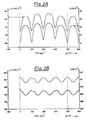
- FIG. 1A and 1B show typical angular velocity profiles raw and smoothed, namely FIG. 1A at low speed and FIG. 1B at high speed.
- FIG. 2A and 2B show the two smoothing steps, again FIG. 2A at low speed and FIG. 2B at high speed.
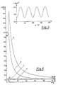
- Fig. 3 shows the course of the crank angle-dependent moment of inertia.
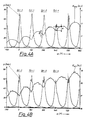
- FIG. 4A and 4B show calculated energy level curves in comparison to measured cylinder pressure curves - FIG. 4A at low speed, FIG. 4B at high speed.
- the device according to the invention for diagnosing internal combustion engines is accordingly designed such that the measuring arrangement has a measuring unit for the continuous measurement of the rotational speed or angular velocity of the internal combustion engine and an associated assignment unit for assigning the respective measurement results to defined crank angle positions of the internal combustion engine, that the evaluation device has a Storage unit in which a respective equivalent moment of inertia I ( ⁇ ) of the internal combustion engine is contained for the defined crank angle positions, that the evaluation unit further comprises a linking unit in which the respective total energy of the internal combustion engine is determined, and that a comparison unit is provided in the evaluation unit, in the one from the comparison of these total energies in cylinder-specific crank angle ranges, the individual cylinder torques and powers are determined.
- I ( ⁇ ) is determined on the basis of motor data that are entered and possibly temporarily stored.
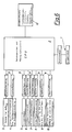
- This "storage unit” for I ( ⁇ ) also includes solutions in which, according to the block diagram of the device according to the invention in FIG. 6, various further signal recording or input options are provided, with the aid of which, for example, an upstream linking unit I ( ⁇ ) can be determined.
- Machine type-specific machine data in particular values for I0, l, r, m os or also pi (n) for determining the p r in the outlet of the machine (see details below) can be entered via an input unit 1.
- I ( ⁇ ) is determined from all these data and temporarily stored for at least one period in the memory unit, which is not described in more detail here.
- a measuring unit 3 for the continuous measurement of the rotational speed or angular velocity of the internal combustion engine and a unit 4 (for example a clamping encoder or an ignition voltage signal transmitter) for cylinder detection for the assignment of the respective measurement results to unit 3.
- a trigger marker is in Fig. 6 designated 5.
- 6 denotes an oil temperature sensor and 7 denotes a water temperature sensor, which are important in connection with the determination of the friction described below.
- 8 denotes an exhaust temperature sensor and 9 denotes a position sensor for the position of the fuel quantity regulator - the signals of these units can be used to at least approximately determine the mean load with which the internal combustion engine being examined is currently running.
- 10 in FIG. 6 denotes possible further sensors for determining the respective angular velocity curve at other locations on the machine train, as are necessary for the determination or consideration of the potential energy.
- units 11 for signal processing are shown in the connection of all the named measuring units or sensors to the evaluation device 2; Output units downstream of the evaluation unit 2, such as a screen, printer, data carrier, interfaces, etc., are designated by 12.
- the invention is therefore based on the fact that for the single-cylinder assessment with regard to torque or power, only a speed or angular velocity relevant to the respective dynamic conditions on the crank mechanism of the internal combustion engine is to be removed as a function of the crank angle position of the internal combustion engine and, in turn, to the Crank angle related respective total moment of inertia I ( ⁇ ) needs to be linked to the respective total kinetic energy stored in the machine.
- ⁇ the crank angle position of the internal combustion engine
- the method or the corresponding device according to the invention is intended for single-cylinder assessment during full load ramp-up (full gas acceleration in a specific speed range, preferably (but not necessarily) without external load on the internal combustion engine); Due to the high accuracy - especially in the low speed range - it is also easily possible to diagnose the differences between the cylinders while idling. In principle, it is also possible to determine the mechanical loss torque of the motor during engine stopping or also to determine the course of the internal single-cylinder torque during full load run-up.
- the first step ⁇ is measured at a point where the moment of inertia of the machine is concentrated as possible, preferably on the flywheel.
- a cylinder in which combustion is currently taking place, is detected, preferably by a separate evaluation unit with an injection line pressure signal or an ignition voltage signal.
- the exact assignment between the ⁇ curve and the crank angle ⁇ is preferably carried out using a trigger mark.
- the ⁇ curve which is calculated directly from the measurement data, is preferably smoothed. If there is no trigger mark, the assignment of the crankshaft angle ( ⁇ ) to the ⁇ curve can also be made using the relative minima in the ⁇ curve. When idling, the relative minima of the ⁇ curve are always in the immediate vicinity of OT.
- the kinetic energy of the oscillating masses can be taken into account and the course of the energy level can be calculated.
- the ring gear of the flywheel has certain manufacturing tolerances and the time measurement is also carried out in discrete steps (e.g. of whole ⁇ sec). This usually results in high-frequency noise on the ⁇ curve.
- Fig. 1 shows an example of the curve over the crank angle ⁇ , as it is shown directly from the recorded measurement data, in comparison to an ⁇ curve (1A at a speed of, for example, calculated from the gas pressures recorded in the cylinders in a conventional manner 770 rpm, 1B at 3740 rpm).
- smoothing e.g. With the help of the moving averaging (over ⁇ 5 points), the course is already very improved.
- the ⁇ curve can be used for evaluation with the aid of the "energy level algorithm" (see FIGS. 2-2A again for 770 / min; 2B for 3740 / min).
- FIG. 4 shows an example of this energy level curve in comparison to the cylinder pressure curves p measured in a conventional manner, again at low (FIG. 4A) and at high speed (FIG. 4B). The effect of the individual cylinders can be seen from the differences in the energy level curve.
- the measured cylinder pressure curves for this example are shown in FIG. 5 in the form of a p-V diagram.
- the pressure curve for the entire cycle of cylinder 1 is entered in dotted lines.
- the range from S1 to E1 means start and end of the gas pressure influence of cylinder 1
- the range from S2 to E2 start and end of the gas pressure influence of cylinder 2 S4 to E4 start and end of the gas pressure influence of cylinder 4 and S3 to E3 Start and end of the gas pressure influence of cylinder 3.
- A denotes the expansion stroke of cylinder 1
- B the compression stroke of cylinder 2
- C the exhaust stroke of cylinder 3
- D the intake stroke of cylinder 4.
- pe * j pi * j - pf * j pi * j is negative in the engine stopping and mainly consists of the losses in the gas exchange and the wall heat losses during the high pressure loop.
- pi * j can be determined for each cylinder j in a unique engine type-specific form as a function of engine speed and engine temperature. With this information, the course of the friction medium pressure pf * j can be determined specifically for the engine during engine stopping.
- a difference can be formed from the energy level curve, which represents part of the compression work or part of the expansion work of a cylinder (e.g. Fig. 4 A, amplitude A). If there is no combustion, i.e. in the outlet or when the engine is towed, this measure can be used very well to compare the relative compression of the cylinders. In the case of combustion, too, it can be continuously checked with the amplitude B (FIG. 4 A) whether the condition of uniform compression is fulfilled.
- Torsional vibrations in the internal combustion engine or in the entire drive train are preferably taken into account by splitting the angle-dependent machine moment of inertia into two or finally many representative partial moments of inertia, the course ⁇ (t) being measured at each of these locations k. (This also changes Ekin)
- the spring constants of the mass-free, elastic connecting elements must be known in order to be able to determine the energy level completely.
- the cylinder head on each cylinder was equipped with a quartz pressure sensor for the gas pressure curve.
- the angle signals for the ⁇ measurement were generated using an inductive encoder. He was at a distance of about 2 mm mounted above the tip circle of the ring gear.
- the angular position of the compression TDC must be assigned as precisely as possible to a measured pressure curve. An error of 1 ° crank angle already results in a pi error of the order of 10%. Therefore, an OT or trigger signal was also recorded with a second inductive encoder. The signal was generated by the passage of a sheet metal plate that was mounted on the flywheel. An adjustment of this leaflet was possible via elongated holes.
- the quartz pressure transducers were connected to a high-speed data acquisition device via four separate charge amplifiers.
- the voltage signals ( ⁇ 10 V) of the inductive speed sensors were also recorded by this device.
- the generated measurement files were processed on a PC (AT - 386).
- a possible error of this method lies in the assumption that the engine torque would be the same function of the speed both in the rapid as well as in the slower full load run-up (with additional flywheel mass).
- the torque is probably somewhat greater when the ramp-up is slower.
- the moment of inertia and the confidence intervals were determined with three different additional flywheels.
- the dependency of the result values on the size of the additional flywheel mass was extrapolated via regression lines to the value of the additional flywheel mass 0:
- the engine moment of inertia of the machine considered here as an example with all rotating masses - reduced to crankshaft speed - and without clutch was therefore between 95 and 95% between 0.293 kgsqm and 0.3257 kgsqm. The average is 0.3087 kgm2.
- a branch was installed in the injection line to the nozzle of cylinder 4.
- a second injector was connected to this branch.
Description
Die Erfindung betrifft ein Diagnoseverfahren für Bennkraftmaschinen, insbesonders für mehrzylindrige Brennkraftmaschinen, wobei fortlaufend Messungen von Betriebskenngrößen, insbesonders von zylinderspezifischen Betriebskenngrößen, durchgeführt und durch Auswertung und Zuordnung der Meßergebnisse die Einzelzylinder-Drehmomente bzw. -Leistungen bestimmt werden. Weiters betrifft die Erfindung auch eine entsprechende Einrichtung zur Diagnose von Brennkraftmaschinen, mit einer Meßanordnung für die fortlaufende Ermittlung von zylinderspezifischen Betriebskenngrößen und einer damit in Verbindung stehenden Auswerteeinrichtung zur Auswertung, Zuordnung und Anzeige von die Einzelzylinder-Leistung repräsentierenden Meßergebnissen.The invention relates to a diagnostic method for internal combustion engines, in particular for multi-cylinder internal combustion engines, measurements of operating parameters, in particular cylinder-specific operating parameters, being carried out continuously and the individual cylinder torques or powers being determined by evaluating and assigning the measurement results. Furthermore, the invention also relates to a corresponding device for the diagnosis of internal combustion engines, with a measuring arrangement for the continuous determination of cylinder-specific operating parameters and an associated evaluation device for evaluating, assigning and displaying measurement results representing the individual cylinder output.
Verfahren und Einrichtungen der genannten Art sind bekannt, werden aber heutzutage üblicherweise nur bei der Konstruktion und Entwicklung von neuen Brennkraftmaschinen oder deren Teilen eingesetzt. Nachteilig ist bei den bisher bekannten Einrichtungen und Verfahren insbesonders der Umstand, daß die Ermittlung von Einzelzylinder-Leistungen bzw. -Drehmomenten jeweils separate Gasdruckmessungen an den einzelnen Zylindern erfordert - die von der Zeit bzw. vom Kurbelwinkel abhängigen Gasdruckverläufe können dann mit den entsprechenden konstruktiven Größen der Brennkraftmaschine verknüpft auf die gesuchten Leistungen bzw. Drehmomente umgelegt werden. Diese Gasdruckmessungen erfordern einen hohen konstruktiven bzw. montagemäßigen Aufwand und sind zur periodischen Kontrolle bzw. Überprüfung von bereits in Betrieb befindlichen Brennkraftmaschinen nur in den seltensten Fällen durchführbar, da zumeist separate Indizierbohrungen oder dergleichen für die Meßwertaufnehmer vorgesehen werden müßten, was insgesamt der Serienanwendung derartiger Diagnosemöglichkeiten entgegensteht.Methods and devices of the type mentioned are known, but nowadays they are usually only used in the design and development of new internal combustion engines or their parts. A disadvantage of the previously known devices and methods is, in particular, the fact that the determination of individual cylinder outputs or torques requires separate gas pressure measurements on the individual cylinders - the gas pressure profiles, which are dependent on time and crank angle, can then be achieved with the corresponding design parameters the internal combustion engine linked to the searched powers or torques. These gas pressure measurements require a high level of design and assembly effort and can only be carried out for the periodic checking or checking of internal combustion engines that are already in operation in the rarest of cases, since mostly separate indexing holes or the like would have to be provided for the measuring sensors, which overall means the series application of such diagnostic options opposes.
Es sind auch Verfahren bekannt, die Näherungsgrößen für die Einzelzylinderleistung aus dem gemessenen Winkelgeschwindigkeitsverlauf bestimmen. So leiten z.B. Schroeder und Thaddens in EP-A-153004 aus gemessenen Musterdruckverläufen, die an dem zu untersuchenden Motortyp nur einmalig aufzunehmen sind, und aktuellen Winkelgeschwindigkeitsmessungen den absoluten Kompressionsenddruck und Einzelzylinderleistungsmaße ab. Nachteilig ist bei dieser Methode der Aufwand zur Beschaffung der gemessenen Druckverläufe sowie die grundsätzliche Einschränkung auf konstante, niedrige Drehzahl, bei der die Massenkraftwirkung noch vernachlässigt werden kann.Methods are also known which determine approximations for the individual cylinder power from the measured angular velocity curve. For example, Schroeder and Thaddens in EP-A-153004 derive the absolute compression end pressure and single-cylinder power measurements from measured sample pressure profiles, which can only be recorded once on the type of engine to be examined, and current angular velocity measurements. A disadvantage of this method is the effort required to obtain the measured pressure profiles and the basic restriction to a constant, low speed, at which the mass force effect can still be neglected.
Dem Problem der störenden Massenkrafteinflüsse bei höheren Drehzahlen begegnen Raid und Taylor in GB-2053484-A indem sie die Beschleunigungsdrehmomente, die sie aus der gemessenen Winkelbeschleunigung des Schwungrades - für einen Zyklus im Hochlauf und einen Zyklus im Motorauslauf - berechnen, voneinander subtrahieren und die Differenzfläche als ein Maß für die im Zylinder umgesetzute Arbeit hernziehen. Nachteilig ist hierbei die Tatsache, daß dieses Verfahren nur an freilaufenden Motoren durchgeführt werden kann, bei denen ein Hochlauf und ein Auslauf aufgezeichnet werden muß.In GB-2053484-A, Raid and Taylor deal with the problem of the disturbing mass forces at higher speeds by calculating the acceleration torques, which they calculate from the measured angular acceleration of the flywheel - for one cycle during run-up and one cycle during engine coast-down. Subtract from each other and use the difference area as a measure of the work done in the cylinder. The disadvantage here is the fact that this method can only be carried out on free-running motors in which a run-up and a run-down must be recorded.
Aufgabe der vorliegenden Erfindung ist es, ein Verfahren bzw. eine Einrichtung der eingangs genannten Art so zu verbessern, daß die genannten Nachteile vermieden werden und daß insbesonders auf einfache, kostengünstige und trotzdem relevante Weise Einzelzylinder-Beurteilungen hinsichtlich Leistung bzw. Drehmoment durchgeführt werden können. Diese Beurteilungen sollen insbesonders ohne die Anbringung zusätzlicher Indizierbohrungen oder dergleichen an den Zylindern der Brennkraftmaschine möglich sein, sodaß auch routinemäßige Untersuchungen an Serienmaschinen durchgeführt werden können.The object of the present invention is to improve a method or a device of the type mentioned at the outset in such a way that the disadvantages mentioned are avoided and that, in particular in a simple, inexpensive but nevertheless relevant manner, single-cylinder assessments can be carried out with regard to power or torque. These assessments should in particular be possible without the attachment of additional indexing holes or the like on the cylinders of the internal combustion engine, so that routine examinations can also be carried out on series machines.
Ein Diagnoseverfahren der eingangs genannten Art ist zur Lösung dieser Aufgabe so ausgebildet, daß - jeweils für definierte Kurbelwinkelstellungen-
- a) an zumindest einem Bauteil der Brennkraftmaschine die jeweilige Drehzahl bzw. Winkelgeschwindigkeit ω(α) gemessen wird,
- b) aus den konstruktiven Daten der Brennkraftmaschine ein kurbelwinkelabhängiges Ersatzträgheitsmoment I(α) gebildet wird, das den Einfluß der oszillierenden Massen mit erfaßt, und
- c) die jeweilige Gesamtenergie, die in der Brennkraftmaschine gespeichert ist, ermittelt wird, und daß
- d) aus dem Vergleich dieser Gesamtenergien in zylinderspezifischen Kurbelwinkelbereichen die Einzelzylinder-Drehmomente bzw. -Leistungen bestimmt werden.
- a) the respective speed or angular velocity ω (α) is measured on at least one component of the internal combustion engine,
- b) a crank angle-dependent equivalent moment of inertia I (α) is formed from the structural data of the internal combustion engine, which also detects the influence of the oscillating masses, and
- c) the respective total energy stored in the internal combustion engine is determined, and that
- d) the comparison of these total energies in cylinder-specific crank angle ranges is used to determine the individual cylinder torques or powers.
Besonders bevorzugt ist insbesonders, daß im Schritt c) nach der Beziehung Egesamt = Ekin + Epot die jeweilige Gesamtenergie, die in der Brennkraftmaschine gespeichert ist, durch die gesamte kinetische Energie angenähert wird, wobei Ekin nach der Beziehung![]()
![]()
Die Erfindung wird in weiterer Folge am Beispiel eines 4-Zylinder-Motors und an der Hand der Figuren näher beschrieben:The invention is described in more detail below using the example of a 4-cylinder engine and the figures:
Fig. 1A und Fig. 1B zeigen typische Winkelgeschwindigkeitsverläufe roh und geglättet, und zwar Fig. 1A bei niedriger und Fig. 1B bei hoher Drehzahl.1A and 1B show typical angular velocity profiles raw and smoothed, namely FIG. 1A at low speed and FIG. 1B at high speed.
Fig. 2A und Fig. 2B zeigen die beiden Glättungsschritte, wieder Fig. 2A bei niedriger und Fig. 2B bei hoher Drehzahl.2A and 2B show the two smoothing steps, again FIG. 2A at low speed and FIG. 2B at high speed.
Fig. 3 zeigt den Verlauf des kurbelwinkelabhängigen Trägheitsmoments.Fig. 3 shows the course of the crank angle-dependent moment of inertia.
Fig. 4A und Fig. 4B zeigen berechnete Energiepegelverläufe im Vergleich zu gemessenen Zylinderdruckverläufen - Fig. 4A bei niedriger Drehzahl, Fig. 4B bei hoher Drehzahl.4A and 4B show calculated energy level curves in comparison to measured cylinder pressure curves - FIG. 4A at low speed, FIG. 4B at high speed.
Fig. 5 unterstützt die Erklärung des "gemischten inneren Mitteldruckes"5 supports the explanation of the "mixed internal mean pressure"
Fig. 6 zeigt ein Beispiel einer Geräteausführung."6 shows an example of a device version. "
Die erfindungsgemäße Einrichtung zur Diagnose von Brennkraftmaschinen ist demgemäß so ausgebildet, daß die Meßanordnung eine Meßeinheit zur fortlaufenden Messung der Drehzahl bzw. Winkelgeschwindigkeit der Brennkraftmaschine sowie eine damit in Verbindung stehende Zuordnungseinheit zur Zuordnung der jeweiligen Meßergebnisse zu definierten Kurbelwinkelstellungen der Brennkraftmaschine aufweist, daß die Auswerteeinrichtung eine Speichereinheit aufweist, in der für die definierten Kurbelwinkelstellungen ein jeweiliges Ersatzträgheitsmoment I(α) der Brennkraftmaschine enthalten ist, daß die Auswerteeinheit weiters eine Verknüpfungseinheit umfaßt, in der die jeweilige Gesamtenergie der Brennkraftmaschine ermittelt wird, und daß eine Vergleichseinheit in der Auswerteeinheit vorgesehen ist, in der aus dem Vergleich dieser Gesamtenergien in zylinderspezifischen Kurbelwinkelbereichen die Einzelzylinder-Drehmomente bzw. -Leistungen bestimmt werden. I (α) wird dabei ermittelt an Hand von Motordaten, die eingegeben werden und unter Umständen zwischengespeichert.The device according to the invention for diagnosing internal combustion engines is accordingly designed such that the measuring arrangement has a measuring unit for the continuous measurement of the rotational speed or angular velocity of the internal combustion engine and an associated assignment unit for assigning the respective measurement results to defined crank angle positions of the internal combustion engine, that the evaluation device has a Storage unit in which a respective equivalent moment of inertia I (α) of the internal combustion engine is contained for the defined crank angle positions, that the evaluation unit further comprises a linking unit in which the respective total energy of the internal combustion engine is determined, and that a comparison unit is provided in the evaluation unit, in the one from the comparison of these total energies in cylinder-specific crank angle ranges, the individual cylinder torques and powers are determined. I (α) is determined on the basis of motor data that are entered and possibly temporarily stored.
Diese "Speichereinheit" für I (α) umfaßt auch Lösungen, bei denen gemäß dem Blockschaltbild der erfindungsgemäßen Einrichtung in Fig. 6 verschiedene weitere Signalaufnahme- bzw. Eingabemöglichkeiten vorgesehen sind, mit deren Hilfe beispielsweise in einer vorgeschalteten Verknüpfungseinheit I (α) ermittelbar ist. Über eine Eingabeeinheit 1 können motortypspezifische Maschinendaten - insbesonders Werte für I₀, l, r, mos oder auch pi(n) für die pr bestimmung im Auslauf der Maschine (siehe Genaueres untenstehend)-eingegeben werden. In der Auswerteeinrichtung 2 wird aus all diesen Daten I (α) ermittelt und in der hier nicht näher bezeichneten Speichereinheit für zumindest eine Periode zwischengespeichert. An Sensoren ist für das erfindungsgemäße Verfahren nur erforderlich eine Meßeinheit 3 zur fortlaufenden Messung der Drehzahl bzw. Winkelgeschwindigkeit der brennkraftmaschine sowie eine Einheit 4 (beispielsweise ein Klemmgeber oder ein Zündspannungssignalgeber) zur Zylindererkennung für die Zuordnung der jeweiligen Meßergebnisse der Einheit 3. Ein Triggermarkengeber ist in Fig. 6 mit 5 bezeichnet. Mit 6 ist ein Öltemperatursensor und mit 7 ein Wassertemperatursensor bezeichnet, die im Zusammenhang mit der untenstehend beschriebenen Ermittlung der Reibung von Bedeutung sind. Mit 8 ist ein Auspufftemperatursensor und mit 9 ein Weggeber für die Stellung des Kraftstoffmengenreglers bezeichnet - mit den Signalen dieser Einheiten kann die mittlere Last, mit der die untersuchte brennkraftmaschine gerade läuft, zumindest angenähert ermittelt werden.This "storage unit" for I (α) also includes solutions in which, according to the block diagram of the device according to the invention in FIG. 6, various further signal recording or input options are provided, with the aid of which, for example, an upstream linking unit I (α) can be determined. Machine type-specific machine data - in particular values for I₀, l, r, m os or also pi (n) for determining the p r in the outlet of the machine (see details below) can be entered via an
Allgemein mit 10 sind schließlich in Fig. 6 mögliche weitere Sensoren für die Ermittlung des jeweiligen Winkelgeschwindigkeitsverlaufes an anderen Orten des Maschinenstranges bezeichnet, wie sie für die Ermittlung bzw. berücksichtigung der potentiellen Energie erforderlich sind.Finally, generally, 10 in FIG. 6 denotes possible further sensors for determining the respective angular velocity curve at other locations on the machine train, as are necessary for the determination or consideration of the potential energy.
In der Verbindung von allen genannten Meßeinheiten bzw. Sensoren mit der Auswerteeinrichtung 2 sind schließlich Einheiten 11 zur Signalaufbereitung eingezeichnet; der Auswerteeinheit 2 nachgeschaltete Ausgabeeinheiten, wie Bildschirm, Drucker, Datenträger, Schnittstellen, usw. sind mit 12 bezeichnet.Finally,
Die Erfindung geht damit also davon aus, daß zur Einzelzylinder-Beurteilung hinsichtlich Drehmoment bzw. Leistung nur eine für die jeweiligen dynamischen Verhältnisse am Kurbeltrieb der brennkraftmaschine relevante Drehzahl bzw. Winkelgeschwindigkeit in Abhängigkeit von der Kurbelwinkelstellung der brennkraftmaschine abgenommen zu werden und mit dem wiederum auf den Kurbelwinkel bezogenen jeweiligen Gesamtträgheitsmoment I (α) zur jeweiligen gesamten, in der Maschine gespeicherten, kinetischen Energie verknüpft zu werden braucht. In zylinderspezifischen Kurbelwinkelbereichen der über dem Kurbelwinkel aufgetragenen Gesamtenergie kann diese dann ohne weiteres den einzelnen hauptverursachenden Zylindern zugeordnet werden, sodaß durch entsprechende Vergleiche die Charakteristiken der Einzelzylinder ermittelbar sind.The invention is therefore based on the fact that for the single-cylinder assessment with regard to torque or power, only a speed or angular velocity relevant to the respective dynamic conditions on the crank mechanism of the internal combustion engine is to be removed as a function of the crank angle position of the internal combustion engine and, in turn, to the Crank angle related respective total moment of inertia I (α) needs to be linked to the respective total kinetic energy stored in the machine. In cylinder-specific crank angle ranges of the total energy plotted over the crank angle, this can then be easily assigned to the individual cylinders which are the main cause, so that the characteristics of the individual cylinders can be determined by corresponding comparisons.
An konstanten, motortypspezifischen Werten muß dabei nur das Trägheitsmoment aller rotierenden Maschinenteile (reduziert auf die Kurbelwellendrehzahl), das Schubstangenverhältnis (Pleuelstangenlänge und Hub) sowie die Summe der oszillierenden Massen pro Zylinder bekannt sein. Grundsätzlich ist das Verfahren bzw. die entsprechende Einrichtung nach der Erfindung für die Einzelzylinder-Beurteilung im Vollasthochlauf (Vollgasbeschleunigung in einem bestimmten Drehzahlbereich, vorzugsweise (aber nicht notwendigerweise) ohne äußere Belastung der brennkraftmaschine) gedacht; aufgrund der hohen Genauigkeit - insbesonders im niederen Drehzahlbereich - ist es etwa ohne weiteres auch möglich, die Unterschiede zwischen den Zylindern im Leerlauf zu diagnostizieren. Grundsätzlich ist es darüber hinaus auch möglich, während des Motorauslaufes das mechanische Verlustmoment des Motors zu bestimmen bzw. weiters auch während des Vollasthochlaufes den Verlauf des inneren Einzelzylinder-Drehmoments zu ermitteln.At constant, engine type-specific values, only the moment of inertia of all rotating machine parts (reduced to the crankshaft speed), the connecting rod ratio (connecting rod length and stroke) and the sum of the oscillating masses per cylinder need to be known. Basically, the method or the corresponding device according to the invention is intended for single-cylinder assessment during full load ramp-up (full gas acceleration in a specific speed range, preferably (but not necessarily) without external load on the internal combustion engine); Due to the high accuracy - especially in the low speed range - it is also easily possible to diagnose the differences between the cylinders while idling. In principle, it is also possible to determine the mechanical loss torque of the motor during engine stopping or also to determine the course of the internal single-cylinder torque during full load run-up.
Prinzipiell gilt, daß sich etwa die effektiven Einzelzylinder-Drehmomentverläufe aus der Zunahme der gespeicherten kinetischen Energie durch die Wirkung eines Zylinders ergeben. Betrachtet man die gesamte Brennkraftmaschine als mechanisches, offenes System, so läßt sich die folgende Energiebilanz ansetzen:![]()
bzw. für den frei laufenden Motor:![]()
wobei gilt:
- Wi
- mechanische Arbeit der Gasdrücke
- Wf
- mechanische Arbeit der Verlustmomente
- Wload
- nach außen abgegebene mechanische Arbeit.
(Bei der freilaufenden Maschine ist Wload = 0) - Ekin
- innerhalb des Motors gespeicherte kinetische Energie.
Sie ist eine Funktion von ω und α. - Epot
- innerhalb des Motors gespeicherte potentielle Energie.
Durch die Verdrehung bzw. Dehnung elastischer Motorelemente wird kurzzeitig auch Energie gespeichert.
Dieser Anteil beeinflußt den ω-Verlauf erst bei höherer Drehzahl.
Weiters ist die Energie, die auf Grund der geodetischen Höhe der oszillierenden Massen gespeichert wird, hier einzuordnen.
or for the free-running motor:
where:
- Wi
- mechanical work of gas pressures
- Wf
- mechanical work of loss moments
- Wload
- mechanical work outsourced.
(Wload = 0 for the free-running machine) - Ekin
- kinetic energy stored within the motor.
It is a function of ω and α. - Epot
- potential energy stored within the motor.
The twisting or stretching of elastic motor elements also temporarily stores energy.
This proportion only influences the ω curve at higher speed.
Furthermore, the energy that is stored due to the geodetic height of the oscillating masses can be classified here.
Diese Beziehungen gelten für beliebige Differenzwinkel.These relationships apply to any difference angle.
Für Verbrennungskraftmaschinen ist es üblich, Wi bzw. Wf über einen Motorzyklus zu bestimmen und auf das Hubvolumen zu beziehen:For internal combustion engines, it is common to determine Wi or Wf over an engine cycle and to refer to the stroke volume:
Für einen Einzelzylindermotor läßt sich bei betrachtung eines Kurbelwinkelintervalles von 720° Gleichung 1 in gewohnter Form anschreiben:![]()
- pe
- effektiver Mitteldruck

- Vh
- Hubvolumen eines Zylinders
- pgas
- Gasdruckverlauf im Brennraum eines Zylinders (er wird üblicherweise mit Druckaufnehmern, die in eigenen Indizierbohrungen angebracht sind, gemessen)
bzw.

- Mf
- Drehmoment aller mechanischen Reibverluste im Motor in seiner Wirkung auf das Schwungrad
- α
- Winkellage der Kurbelwelle
Diese Werte gelten jeweils für einen Zylinder. Die gesamte im Motor gespeicherte Energie wird aber von allen Zylindern gemeinsam beeinflußt. Sie besitzen allerdings unterschiedliche Lagen im Arbeitsprozeß.For a single cylinder engine, considering a crank angle interval from 720 °
- pe
- effective medium pressure
- Vh
- Stroke volume of a cylinder
- pgas
- Gas pressure curve in the combustion chamber of a cylinder (it is usually measured with pressure transducers that are installed in their own indexing holes)
respectively.
- Mf
- Torque of all mechanical friction losses in the engine in its effect on the flywheel
- α
- Angular position of the crankshaft
These values apply to one cylinder each. The total energy stored in the engine is influenced by all cylinders together. However, they have different positions in the work process.
Für den 4-Zylinder Reihenmotor im 4-Taktverfahren wird daher beispielsweise die Differenz der gespeicherten Energie in einem Intervall von △α = 720/4 = 180° KW durchgeführt. Es ergeben sich dabei "gemischte Mitteldrücke", die grundsätzlich von allen Zylindern, hauptsächlich aber von jenem der sich gerade in einem entscheidenden Teil der Hochdruckschleife befindet, beeinflußt wird. Diese "gemischten Mitteldrücke" werden mit einem * gekennzeichnet. ("j" ist der Index für den betrachteten Zylinder)
![]()
![]()
Es kann also aus dem Energiepegelverlauf eine Betriebskenngröße abgeleitet werden, die unter bestimmten Voraussetzungen exakt (siehe unten)-einem "effektiven Mitteldruck", bzw. bei Berücksichtigung der Motorreibung einem "inneren Mitteldruck" eines bestimmten Zylinders entspricht.It is therefore possible to derive an operating parameter from the energy level curve which, under certain conditions, corresponds exactly (see below) to an "effective medium pressure" or, taking engine friction into account, an "internal medium pressure" of a specific cylinder.
Es hat sich in den bisher durchgeführten Versuchen gezeigt, daß der Einfluß der Torsionsschwingungen (Epot) bei der Bestimmung des Energiepegelverlaufes vernachlässigt werden kann, wobei erst bei höheren Drehzahlen merkliche Abweichungen zu den mit Quarzdruckaufnehmern bestimmten Referenzwerten auftraten.It has been shown in the experiments carried out so far that the influence of the torsional vibrations (Epot) can be neglected when determining the energy level curve, with noticeable deviations from the reference values determined with quartz pressure sensors only occurring at higher speeds.
In diesem Fall gilt:
Bei der meßtechnischen Methode der "Energiepegelauswertung" wird im ersten Schritt ω an einer Stelle gemessen, an der das Trägheitsmoment der Maschine möglichst konzentriert ist, vorzugsweise am Schwungrad. Zusätzlich wird, bevorzugt von einer eigenen Auswerteeinheit mit einem Einspritzleitungsdrucksignal, bzw. einem Zündspannungssignal, ein Zylinder detektiert, in dem gerade eine Verbrennung stattfindet. Die genaue Zuordnung zwischen dem ω-Verlauf und dem Kurbelwinkel α erfolgt vorzugsweise mit einer Triggermarke. In weiterer Folge wird der ω-Verlauf, der sich direkt aus den Meßdaten errechnet, vorzugsweise geglättet. Ist keine Triggermarke vorhanden, kann die Zuordnung des Kurbelwellenwinkels (α) zum ω-Verlauf auch an Hand der relativen Minima im ω-Verlauf getroffen werden. Im Leerlauf liegen die relativen Minima des ω-Verlaufes stets in unmittelbarer Nähe von OT.In the metrological method of "energy level evaluation", the first step ω is measured at a point where the moment of inertia of the machine is concentrated as possible, preferably on the flywheel. In addition, a cylinder, in which combustion is currently taking place, is detected, preferably by a separate evaluation unit with an injection line pressure signal or an ignition voltage signal. The exact assignment between the ω curve and the crank angle α is preferably carried out using a trigger mark. Subsequently, the ω curve, which is calculated directly from the measurement data, is preferably smoothed. If there is no trigger mark, the assignment of the crankshaft angle (α) to the ω curve can also be made using the relative minima in the ω curve. When idling, the relative minima of the ω curve are always in the immediate vicinity of OT.
Mit dieser Information kann die kinetische Energie der oszillierenden Massen mitberücksichtigt und der Verlauf des Energiepegels berechnet werden.With this information, the kinetic energy of the oscillating masses can be taken into account and the course of the energy level can be calculated.
Aus sieben grundsätzlichen Differenzbildungsmethoden wurde jene ausgewählt, bei der die beste Übereinstimmung zwischen pe*j und dem entsprechenden, z.B. mit Quarzdruckaufnehmern ermittelten, pej erreicht werden konnte.From seven basic methods of difference formation, the one was selected in which the best match between pe * j and the corresponding pe j , which was determined, for example, using quartz pressure sensors, could be achieved.
Die Drehzahlerfassung erfolgt vorzugsweise über die Zähne des Zahnkranzes, die als Winkelmarken verwendet werden. Die Winkelgeschwindigkeit ergibt sich aus ω =![]()
- △α
- (= z.B. 3,33° bei beispielsweise 108 Zähnen)
- △t
- Zeitdifferenz zwischen zwei Zähnen.
Ein Datenerfassungsgerät interpoliert innerhalb dieser Winkelschritte z.b. noch auf eine
- △ α
- (= e.g. 3.33 ° with 108 teeth, for example)
- △ t
- Time difference between two teeth.
A data acquisition device interpolates within these angular steps, for example to a measurement resolution of 1 ° KW.
Der Zahnkranz des Schwungrades weist aber gewisse Fertigungstoleranzen auf und auch die Zeitmessung wird in diskreten Schritten (z.B. von ganzen µsec) durchgeführt. Daraus ergibt sich üblicherweise ein hochfrequentes Rauschen auf dem ω-Verlauf.However, the ring gear of the flywheel has certain manufacturing tolerances and the time measurement is also carried out in discrete steps (e.g. of whole µsec). This usually results in high-frequency noise on the ω curve.
Fig. 1 zeigt ein beispiel für den -Verlauf über dem Kurbelwinkel α, wie er sich direkt aus den aufgenommenen Meßdaten darstellt, im Vergleich zu einem beispielsweise aus den auf konventionelle Weise aufgenomenen Gasdrücken in den Zylindern berechneten ω-Verlauf (1A bei einer Drehzahl von 770/min, 1B bei 3740/min). Nach einer Glättung, z.B. mit Hilfe der gleitenden Mittelwertbildung (über ± 5 Punkte), ergibt sich ein bereits sehr verbesserter Verlauf. Nach z.B. einer zweiten Glättung gleicher Art kann der ω-Verlauf zur Auswertung mit Hilfe des "Energiepegelalgorithmus" herangezogen werden (siehe dazu Fig. 2-2A wieder für 770/min; 2B für 3740/min).Fig. 1 shows an example of the curve over the crank angle α, as it is shown directly from the recorded measurement data, in comparison to an ω curve (1A at a speed of, for example, calculated from the gas pressures recorded in the cylinders in a conventional manner 770 rpm, 1B at 3740 rpm). After smoothing, e.g. With the help of the moving averaging (over ± 5 points), the course is already very improved. After e.g. In a second smoothing of the same type, the ω curve can be used for evaluation with the aid of the "energy level algorithm" (see FIGS. 2-2A again for 770 / min; 2B for 3740 / min).
Aus dem ω-Verlauf kann nun im Leerlauf die Winkellage der oberen Totpunkte ermittelt werden: Für eine praktisch untersuchte Brennkraftmaschine lag das relative Minimum des ω-Verlaufes im Gutzustand stets bei 1° KW nach OT.From the ω curve, the angular position of the upper one can now be idle Dead points are determined: For a practically examined internal combustion engine, the relative minimum of the ω curve in the good state was always 1 ° KW after TDC.
Auch im Schlechtzustand lag dieses Minimum innerhalb von +1bis +4° KW nach OT, obwohl Zylinder 3 beispielsweise bereits mit ca. 33% der Vollast betrieben und Zylinder 4 geschleppt wurde, und somit nicht mehr direkt vom Leerlauf gesprochen werden kann. Ein entsprechendes Auswertegerät kann dabei auch im Leerlauf auf diese Weise die OT-Lage erkennen bzw. einregeln. Bei den durchgeführten Messungen wurde die OT-Lage mit einer Triggermarke erfaßt. Ist die OT-Lage eines Zylinders (auf welche Weise auch immer) bekannt, so kann die im Motor gespeicherte kinetische Energie berechnet werden: Die Berücksichtigung der oszillierenden Massen erfolgt dabei durch die Einführung eines winkelabhängigen Ersatzträgheitsmomentes, das den Einfluß der oszillierenden Massen berücksichtigt. Allgemein gilt für die n-Zylinder Hubkolbenmaschine:![]()
- I₀
- Trägheitsmoment aller rotierenden Motorteile
- Ios
- fiktiver Trägheitsmomentenanteil zur Berücksichtigung der oszillierenden Massen.
Ansatz:

bzw. Ansatz für den Zylinder j:

Für eine n-zylindrige Hubkolbenmaschine wirkt die Summe aller oszillierenden Trägheitsmassen unter Berücksichtigung der jeweiligen Phasenlage der Kurbelkröpfung αj
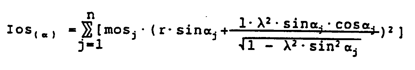
- mos
- oszillierende Masse pro Zylinder
- r
- halber Hub
- l
- Pleulstangenlänge
- λ =
-

- αj =
- Kurbelwinkel des Zylinder j
- I₀
- Moment of inertia of all rotating motor parts
- Ios
- fictitious moment of inertia to take into account the oscillating masses.
Approach:
or approach for cylinder j :
For an n-cylinder reciprocating piston machine, the sum of all oscillating inertial masses takes into account, taking into account the respective phase position of the crank offset α j
- mos
- oscillating mass per cylinder
- r
- half stroke
- l
- Connecting rod length
- λ =
-
- α j =
- Crank angle of the cylinder j
Fig. 3 zeigt beispielsweise den Verlauf dieses Trägheitsmomentes I (α) einer konkreten Maschine als Funktion des Kurbelwinkels α. Es ist unabhängig von der Drehzahl.3 shows, for example, the course of this moment of inertia I (α) of a specific machine as a function of the crank angle α. It is independent of the speed.
Der Energiepegelverlauf ergibt sich aus![]()
![]()
Fig. 4 zeigt ein Beispiel dieses Energiepegel-Verlaufs im Vergleich zu den auf konventionelle Weise gemessenen Zylinderdruckverläufen p und zwar wieder bei niedriger (Fig. 4A) und bei hoher Drehzahl (Fig. 4B). Die Wirkung der einzelnen Zylinder läßt sich an den Differenzen im Energiepegelverlauf erkennen.FIG. 4 shows an example of this energy level curve in comparison to the cylinder pressure curves p measured in a conventional manner, again at low (FIG. 4A) and at high speed (FIG. 4B). The effect of the individual cylinders can be seen from the differences in the energy level curve.
Die Differenzenbildung kann dabei grundsätzlich auf sieben unterschiedlichen Arten erfolgen:
- 1. Betrachtung der Maxima
- 1.a) Differenz zwischen zwei aufeinanderfolgenden relativen Maxima
- 1.b) Differenz zwischen dem einen
Maximum und dem 180° KW davor liegenden Energiepegelwert - 1.c) Differenz zwischen einem
Maximum und dem 180° KW später liegenden Energiepegelwert
- 2. Betrachtung der Minima
- 2.a) Differenz zwischen zwei aufeinanderfolgenden relativen Minima
- 2.b) Differenz zwischen einem
Minimum und dem 180° KW davor liegenden Energiepegelwert - 2.c) Differenz zwischen einem
Minimum und dem 180° KW später liegenden Energiepegelwert
- 3. Vergleich der Energiepegelwerte in den oberen Totpunkten
- 1. Consideration of the maxima
- 1.a) Difference between two successive relative maxima
- 1.b) Difference between the one maximum and the 180 ° KW previous energy level value
- 1.c) Difference between a maximum and the energy level value lying 180 ° KW later
- 2. Consideration of the minima
- 2.a) Difference between two successive relative minima
- 2.b) Difference between a minimum and the energy level value in front of it 180 ° KW
- 2.c) difference between a minimum and the energy level value lying 180 ° KW later
- 3. Comparison of the energy level values in the top dead centers
Während die Methoden 1.a) bis 1.c) deutlich ungenauere Ergebnisse brachten, sind die Methoden 2.a) bis 2.c) und 3. ungefähr gleich genau. Die beste Übereinstimmung wurde mit der Methode 2.b) erreicht.While methods 1.a) to 1.c) produced significantly less precise results, methods 2.a) to 2.c) and 3. are approximately equally accurate. The best agreement was achieved with method 2.b).
Die genannten "gemischten Mitteldrücke" pe*j bzw. pi*j lassen sich folgendermaßen darstellen:
Während der Bestimmung des Einzelzylinder-Drehmomentes - beispielsweise von Zylinder 1 - befinden sich bei einer 4-Zylinder Reihenmaschine (Zündfolge: 1, 2, 4, 3)
- in der Kompression
- :
Zylinder 2, - in der Expansion
- :
Zylinder 1, - beim Ausschieben
- :
Zylinder 3 und - beim Ansaugen
- :
Zylinder 4.
Alle Druckverläufe gemeinsam beeinflussen die Drehbewegung des Schwungrades.The "mixed mean pressures" pe * j and pi * j can be represented as follows:
During the determination of the single cylinder torque - for example from Cylinder 1 - are on a 4-cylinder in-line engine (firing order: 1, 2, 4, 3)
- in compression
- :
Cylinder 2, - in the expansion
- :
Cylinder 1, - when pushing out
- :
Cylinder 3 and - when sucking
- :
Cylinder 4.
All pressure profiles together influence the rotation of the flywheel.
Die gemessenen Zylinderdruckverläufe für dieses beispiel sind in Fig. 5 in Form eines p-V-Diagrammes dargestellt. Punktiert ist der Druckverlauf für den gesamten Zyklus von Zylinder 1 eingetragen. Weiters bedeutet der Bereich von S1 bis E1 Start und Ende des Gasdruck-Einflusses von Zylinder 1, der Bereich von S2 bis E2 Start und Ende des Gasdruck-Einflusses von Zylinder 2, S4 bis E4 Start und Ende des Gasdruck-Einflusses von Zylinder 4 und S3 bis E3 Start und Ende des Gasdruck-Einflusses von Zylinder 3. Mit A ist der Expansionshub von Zylinder 1 gekennzeichnet, mit B der Kompressionshub von Zylinder 2, mit C der Auspuffhub von Zylinder 3 und mit D der Einlaßhub von Zylinder 4.The measured cylinder pressure curves for this example are shown in FIG. 5 in the form of a p-V diagram. The pressure curve for the entire cycle of
Man sieht, daß sich der punktiert eingetragene Verlauf von Zylinder 1 bis auf kleine Unterschiede im Ladungswechsel mit den entsprechenden Teilen der Druckverläufe der Zylinder 2, 3 und 4 deckt. Wären sie absolut identisch, so wäre pi* definitionsgemäß gleich pi. Es wird somit bei der hier betrachteten, erfindungsgemäßen Einzelzylinder-Drehmomentbestimmung mit Hilfe der Energiepegelmethode davon ausgegangen, -daß der Kompressionsdruckverlauf für alle Zylinder ähnlich ist
- und daß im Ladungswechsel keine großen Unterschiede zwischen den einzelnen Zylindern bestehen.It can be seen that the dotted curve of
- And that there are no major differences between the individual cylinders in the gas exchange.
Diese sogenannte Energiepegelmethode ist weiters auch in der Lage, während des Motorauslaufes den effektiven gemischten Mitteldruck (pe*) jedes einzelnen Zylinders in jedem Motorzyklus zu bestimmen:![]()
pi*j ist im Motorauslauf negativ und setzt sich hauptsächlich aus den Verlusten im Ladungswechsel und den Wandwärmeverlusten während der Hochdruckschleife zusammen. Im Rahmen einer Motorreibungsuntersuchung kann pi*j für jeden Zylinder j in einmaliger motortypspezifischer Form als Funktion der Motordrehzahl und der Motortemperatur bestimmt werden. Mit dieser Information kann der Verlauf des Reibmitteldruckes pf*j während des Motorauslaufes motorspezifisch ermittelt werden.This so-called energy level method is also able to determine the effective mixed mean pressure (pe *) of each individual cylinder in each engine cycle during engine shutdown: ![]()
pi * j is negative in the engine stopping and mainly consists of the losses in the gas exchange and the wall heat losses during the high pressure loop. As part of an engine friction analysis, pi * j can be determined for each cylinder j in a unique engine type-specific form as a function of engine speed and engine temperature. With this information, the course of the friction medium pressure pf * j can be determined specifically for the engine during engine stopping.
Die Energiepegelmethode liefert grundsätzlich pe*j bzw. Me*. Hat man im Motorauslauf pf*j bzw. Mf*j als Funktion der Drehzahl bestimmt, so kann in einem darauffolgenden Motorhochlauf oder auch im Leerlauf pi*j bzw. Mi*j errechnet werden:![]()
Dabei wird die Lastabhängigkeit von Mf wieder vernachlässigt, was sich als zumeist durchaus zulässig erwiesen hat. Mit Hilfe von Mi* kann dann beispielsweise die eingespritzte Kraftstoffmenge ohne Einfluß der Motorreibung beurteilt werden.The energy level method always provides pe * j or Me *. If pf * j or Mf * j has been determined as a function of the speed in the engine coasting, pi * j or Mi * j can be calculated in a subsequent engine start-up or also when idling: ![]()
The load dependency of Mf is again neglected, which has mostly proven to be quite permissible. Mi * can then be used, for example, to assess the amount of fuel injected without the influence of engine friction.
Weiters kann aus dem Energiepegelverlauf auch eine Differenz gebildet werden, die einen Teil der Kompressionsarbeit, bzw. einen Teil der Expansionsarbeit eines Zylinders repräsentiert (z.B.: Fig. 4 A, Amplitude A). Findet keine Verbrennung statt, also im Auslauf oder bei geschlepptem Motor, kann dieses Maß sehr gut zum Vergleich der relativen Kompression der Zylinder herangezogen werden. Auch im Fall der Verbrennung kann mit der Amplitude B (Fig. 4 A) fortlaufend überprüft werden, ob die Bedingung gleichmäßiger Kompression erfüllt ist.Furthermore, a difference can be formed from the energy level curve, which represents part of the compression work or part of the expansion work of a cylinder (e.g. Fig. 4 A, amplitude A). If there is no combustion, i.e. in the outlet or when the engine is towed, this measure can be used very well to compare the relative compression of the cylinders. In the case of combustion, too, it can be continuously checked with the amplitude B (FIG. 4 A) whether the condition of uniform compression is fulfilled.
Das bisherige Gesagte bezieht sich grundsätzlich auf freilaufende Brennkraftmaschinen. In Gleichung 1a ist aber der Fall der belasteten Maschine mit Wload bereits berücksichtigt. Messungen an belasteten Maschinen haben bestätigt, daß sich die -Verläufe in entsprechender Form darstellen. Der relative Kompressions-, bzw. Drehmoment-, bzw. Leistungsanteil eines Zylinders läßt sich also an der belasteten Maschine in gleicher Art und Weise bestimmen. Wird darüber hinaus auch die mittlere Last der Maschine - z.B. aus der Abgastemperatur oder aus der Gashebelstellung in Verbindung mit der Drehzahl und einem entsprechenden motortypischen Kennfeld, das einmalig auf einem Motorprüfstand bestimmt wurde - angenähert, so kann das effektive Einzelzylinderdrehmoment, bzw. die effektive Einzelzylinderleistung, wieder absolut angegeben werden:
In Ekin ist dabei natürlich die kinetische Energie des gesamten Antriebsstranges zu berücksichtigen.What has been said so far basically relates to free-running internal combustion engines. In equation 1a, however, the case of the loaded machine with W load is already taken into account. Measurements on loaded machines have confirmed that the curves are in an appropriate form. The relative compression, or torque, or power share of a cylinder can thus be determined in the same way on the loaded machine. If the mean load of the machine is also approximated - e.g. from the exhaust gas temperature or from the throttle lever position in connection with the speed and a corresponding engine-typical characteristic map that was determined once on an engine test bench - then the effective single cylinder torque or the effective single cylinder output can be determined , again absolutely stated:
In Ekin, of course, the kinetic energy of the entire drive train must be taken into account.
Die potentiell gespeicherte Energie wird gegebenenfalls folgendermaßen berücksichtigt:
Unter Epot wird dann die Summe aus Epot h (infolge der geodetischen Höhe der oszillierenden Massen) und Epot c (die noch nicht berücksichtigte Federspeicherenergie in den elastischen Maschinenelementen) erfaßt:![]()
Ist der Anteil der geodätischen Höhe der oszillierenden Massen von Einfluß, so wird für die n-Zylinder Hubkolbenmaschine
hj = geodätische Höhe des Schwerpunkte der oszillierenden Massen im Zylinder j
im Energiepegelverlauf eingerechnet.The potentially stored energy may be taken into account as follows:
The sum of Epot h (due to the geodetic height of the oscillating masses) and Epot c (the spring energy not yet taken into account in the elastic machine elements) is then recorded under Epot: ![]()
If the proportion of the geodetic height of the oscillating masses has an influence, then the n-cylinder reciprocating engine
h j = geodetic height of the center of gravity of the oscillating masses in the cylinder j
included in the energy level curve.
Die Berücksichtigung von Drehschwingungen in der Brennkraftmaschine oder im gesamten Antriebsstrang erfolgt vorzugsweise durch Aufspaltung des winkelabhängigen Maschinenträgheitsmomentes in zwei bis endlich viele (n) repräsentative Teilträgheitsmomente, wobei an jedem dieser Orte k der Verlauf ω(t) gemessen wird. (Dadurch ändert sich auch Ekin)Torsional vibrations in the internal combustion engine or in the entire drive train are preferably taken into account by splitting the angle-dependent machine moment of inertia into two or finally many representative partial moments of inertia, the course ω (t) being measured at each of these locations k. (This also changes Ekin)
Die Federkonstanten der masselos gedachten, elastischen Verbindungselemente müssen bekannt sein, um den Energiepegel vollständig bestimmen zu können.The spring constants of the mass-free, elastic connecting elements must be known in order to be able to determine the energy level completely.
Dämpfungen brauchen nicht angesetzt zu werden, da die entsprechenden Verluste zum Reibungsverlust gezählt werden und damit dem Pegel der gespeicherten Energie nicht mehr angehören: Ansatz elastisch: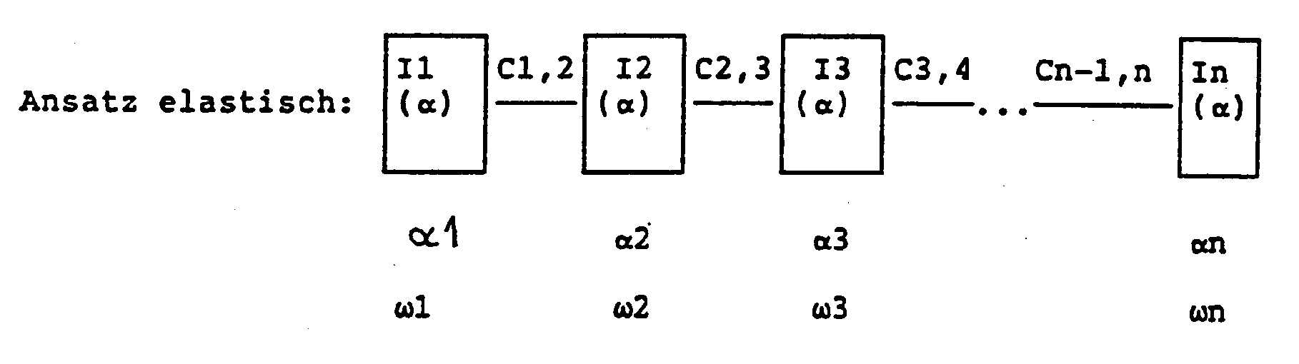


Zur eingangs angesprochenen, bekannten Bestimmung des inneren Einzelzylinder-Drehmomentes zur Überprüfung des erfindungsgemäßen Verfahrens wurde der Zylinderkopf an jedem Zylinder mit einem Quarzdruckaufnehmer für den Gasdruckverlauf ausgerüstet. Die Winkelsignale für die ω-Messung wurden mit Hilfe eines induktiven Gebers erzeugt. Er wurde in einem Abstand von ca 2 mm über dem Kopfkreis des Zahnkranzes montiert. Um indizierte Mitteldrücke berechnen zu können, muß einem gemessenen Druckverlauf möglichst genau die Winkellage des Kompressions-OT zugeordnet werden. Ein Fehler von 1° Kurbelwinkel hat dabei bereits einen pi-Fehler in der Größenordnung von 10 % zur Folge. Daher wurde mit einem zweiten induktiven Geber auch ein OT- bzw. Triggersignal aufgenommen. Das Signal wurde durch den Vorbeigang eines Blechplättchens erzeugt, das am Schwungrad montiert war. Eine Justierung dieses Blättchens war über Langlöcher möglich.For the above-mentioned, known determination of the internal single cylinder torque for checking the method according to the invention, the cylinder head on each cylinder was equipped with a quartz pressure sensor for the gas pressure curve. The angle signals for the ω measurement were generated using an inductive encoder. He was at a distance of about 2 mm mounted above the tip circle of the ring gear. In order to be able to calculate indicated mean pressures, the angular position of the compression TDC must be assigned as precisely as possible to a measured pressure curve. An error of 1 ° crank angle already results in a pi error of the order of 10%. Therefore, an OT or trigger signal was also recorded with a second inductive encoder. The signal was generated by the passage of a sheet metal plate that was mounted on the flywheel. An adjustment of this leaflet was possible via elongated holes.
Die genaue Lage des Kompressions-OT wurde zusätzlich mit Hilfe seines kapazitiven OT-Sensors bestimmt und danach das Blättchen justiert. Die Genauigkeit dieses kapazitiven OT-Sensors ist besser als ± 0,1° Kurbelwinkel.The exact position of the compression TDC was also determined with the aid of its capacitive TDC sensor and the leaflet was then adjusted. The accuracy of this capacitive TDC sensor is better than ± 0.1 ° crank angle.
Die Quarzdruckaufnehmer waren über vier separate Ladungsverstärker an ein Hochgeschwindigkeitsdatenerfassungsgerät angeschlossen. Die Spannungssignale (± 10 V) der induktiven Drehzahlgeber wurden ebenfalls von diesem Gerät aufgenommen.The quartz pressure transducers were connected to a high-speed data acquisition device via four separate charge amplifiers. The voltage signals (± 10 V) of the inductive speed sensors were also recorded by this device.
Die erzeugten Meßfiles wurden auf einem PC (AT - 386) weiter verarbeitet.The generated measurement files were processed on a PC (AT - 386).
Vergleicht man die ermittelte Winkelbeschleunigung aus einem gewöhnlichen Vollasthochlauf mit jener aus einem zweiten Hochlauf, bei dem eine bekannte Zusatzschwungmasse am Schwungrad montiert wurde, so läßt sich aus![]()
das Trägheitsmoment des Motors I₀ berechnen:![]()
- I₁
- bekanntes Trägheitsmoment der Zusatzschwungmasse
- Me
- effektives Motordrehmoment aller Zylinder
calculate the moment of inertia of the motor I₀:
- I₁
- known moment of inertia of the additional flywheel mass
- M e
- effective engine torque of all cylinders
Mit Hilfe von statistischen Verfahren kann aus mehreren (z.B. fünf) Wiederholungen dieser Messung auch ein Bereich angegeben werden, in dem sich das wahre Motorträgheitsmoment mit 95 %-iger Wahrscheinlichkeit befindet.With the help of statistical methods, several (e.g. five) Repetitions of this measurement also indicate a range in which the true motor moment of inertia is with a 95% probability.
Ein möglicher Fehler dieses Verfahrens liegt dabei aber in der Annahme, daß das Motordrehmoment sowohl im raschen als auch im langsameren Vollasthochlauf (mit Zusatzschwungmasse) die gleiche Funktion der Drehzahl wäre. Trotz der mechanischen Blockierung von den förderdruckabhängigen Regelelementen der Einspritzpumpe (Spritzversteller und Vollastmengenregelung) ist das Drehmoment beim langsameren Hochlauf vermutlich etwas größer.A possible error of this method lies in the assumption that the engine torque would be the same function of the speed both in the rapid as well as in the slower full load run-up (with additional flywheel mass). Despite the mechanical blocking of the injection pump-dependent control elements of the injection pump (injection adjuster and full-load quantity control), the torque is probably somewhat greater when the ramp-up is slower.
Daher wurde folgende Vorgangsweise gewählt: Trägheitsmoment und Vertrauensbereiche wurden mit drei verschiedenen Zusatzschwungmassen bestimmt. Die Abhängigkeit der Ergebniswerte von der Größe der Zusatzschwungmasse wurde über Regressionsgeraden auf den Wert der Zusatzschwungmasse 0 extrapoliert: Das Motorträgheitsmoment der hier als Beispiel betrachteten Maschine mit allen rotierenden Massen - reduziert auf Kurbelwellendrehzahl - und ohne Kupplung lag demnach mit 95 %-iger Wahrscheinlichkeit zwischen 0,293 kgm² und 0,3257 kgm². Der Mittelwert beträgt 0,3087 kgm².The following procedure was therefore chosen: The moment of inertia and the confidence intervals were determined with three different additional flywheels. The dependency of the result values on the size of the additional flywheel mass was extrapolated via regression lines to the value of the additional flywheel mass 0: The engine moment of inertia of the machine considered here as an example with all rotating masses - reduced to crankshaft speed - and without clutch was therefore between 95 and 95% between 0.293 kgsqm and 0.3257 kgsqm. The average is 0.3087 kgm².
Dieser Mittelwert erwies sich in der ω-Simulationsrechnung als zu niedrig: der berechnete ω-Verlauf stieg deutlich stärker an als der gemessene.This mean value was found to be too low in the ω simulation calculation: the calculated ω curve increased significantly more than the measured one.
Mit I = 0.3155 kgm² wurde für den berechneten ω-Verlauf die gleiche mittlere Winkelbeschleunigung erhalten wie für den gemessenen.With I = 0.3155 kgm², the same mean angular acceleration was obtained for the calculated ω curve as for the measured one.
Zur Simulation einer Fehlfunktion wurde in die Einspritzleitung zur Düse des Zylinders 4 eine Abzweigung eingebaut. An dieser Abzweigung wurde eine zweite Einspritzdüse angeschlossen.To simulate a malfunction, a branch was installed in the injection line to the nozzle of
Durch Verstellen des Öffnungsdruckes dieser Düse konnte die Einspritzmenge und damit die Einzelzylinder-Leistung von Zylinder 4 geändert werden.By adjusting the opening pressure of this nozzle, the injection quantity and thus the single cylinder output of
Claims (20)
- Diagnostic method for internal combustion engines, in particular for multi-cylinder engines, in which continuous measurements are made of operating magnitudes, in particular cylinder-specific magnitudes, and by evaluation and association of the measured results the individual cylinder torques and performances are determined, and in which, for respective defined crankshaft positions,a) on at least one component of the engine the respective rotational speed or angular velocity ω(α) is measured,b) from the design data of the engine a substitute moment of inertia I (α) dependent on crankshaft position is formed, incorporating the influence of the oscillating masses, andc) the prevailing total energy which is stored in the engine is obtained, and thatd) the individual cylinder torques and performances are determined from this comparison of these total energies in cylinder-specific crankshaft angle ranges.
- Diagnostic method according to claim 1 characterised in that, in the step c), in accordance with the relationship Etotal = Ekin + Epot the respective total energy which is stored in the engine is approached by the overall kinetic energy, Ekin being determined in accordance with the relationship

- Diagnostic method according to claim 1 or 2 for engines with a flywheel which is mounted on one end of the crankshaft and has a starter ring, characterised in that the angular velocity in step a) is measured at the starter ring of the flywheel, preferably by contactless inductive proximity measurement.
- Diagnostic method according to one of claims 1 to 3 characterised in that the association of the measured rotational speed or angular velocity with the respective crank angle is achieved by means of a crankshaft trigger mark and an ignition or injection signal.
- Diagnostic method according to one of claims 1 to 3 characterised in that the occurrence of characteristic crankshaft angular positions, preferably TDC, is determined from the course of the angular velocity.
- Diagnostic method according to one of claims 1 to 5 characterised in that the measurement in step a) is performed at full-load high speed of the free-running engine.
- Diagnostic method according to one of claims 1 to 5 characterised in that the measurement in step a) is performed in the run-down of the free-running engine and/or thereby the cylinder specific engine friction is obtained, preferably while additionally taking into account losses specific to the type of engine in the course of the gas pressure, determined once and for all for an engine type on a test bench.
- Diagnostic method according to one of claims 1 to 5 characterised in that the measurement in step a) is performed on a free-running engine with any desired operating conditions or alterations in operating conditions.
- Diagnostic method according to claims 6 and 7 characterised in that the individual cylinder torques are determined, corresponding in total at least approximately to the internal engine torque.
- Diagnostic method according to one of claims 1 to 9 characterised in that the measurement is carried out on an engine under load, and in addition the average engine load is determined for determination of the absolute values of the individual cylinder torques.
- Diagnostic method according to one of claims 1 to 10 characterised in that the measured values for rotational speed or angular velocity are modified, preferably smoothed with respect to time, before further handling.
- Diagnostic method according to one of claims 1 to 11 characterised in that defined crankshaft angular positions spaced 1° apart are employed.
- Diagnostic method according to one of claims 1 to 12 characterised in that the stored total energy in step c) is determined as Etotal = Ekin + Epot, in which in Epot the rotational oscillation behaviour of the engine as spring-stored energy in the elastic engine components and/or the geodetic height of the oscillating masses is taken into account.
- Diagnostic method according to one of claims 1 to 13 characterised in that operating magnitudes for the relative compressions are determined from the course of the stored energy and are taken into account in the comparison according to step d).
- Apparatus for diagnosis of internal combustion engines with a measuring arrangement for the continuous determination of cylinder-specific operating magnitudes which includes a measuring unit for the continuous measurement of the rotational speed or angular velocity of the engine as well as an associating unit connected to it for associating the respective measured results with defined crankshaft positions of the engine, and an evaluating device connected to it for evaluating, associating and displaying measured results representing individual cylinder performance, the evaluating device having a storage unit in which is contained a respective substitute moment of inertia I (α) of the engine for the defined crankshaft positions, and the evaluating device further including a coupling unit in which the respective total energy of the engine is determined, and a comparison unit being provided in the evaluating unit, in which the individual cylinder torques and performances are determined by comparison of these total energies in cylinder-specific crankshaft position ranges.
- Apparatus according to claim 15 for engines with a flywheel mounted on one end of the crankshaft and having a starter ring, characterised in that there is arranged in the region of the starter ring of the flywheel of the engine under test an angular velocity sensor, preferably a contactlessly operating inductive proximity sensor co-operating with the teeth, and connected to the measuring unit.
- Apparatus according to claim 16 characterised in that in addition a TDC sensor is provided on the flywheel and is connected to the associating unit.
- Apparatus according to one of claims 15 to 17 characterised in that a modulating unit for the measured signal is inserted between the measuring and associating unit and the evaluating device.
- Apparatus according to one of claims 15 to 18 characterised in that the engine under test is connected to a dynamometer for loading it with a load, preferably a respective known load.
- Apparatus according to one of claims 15 to 19 characterised in that a separate arrangement for determining the relative compression of individual cylinders is provided on the engine and connected to the evaluating device.
Applications Claiming Priority (2)
| Application Number | Priority Date | Filing Date | Title |
|---|---|---|---|
| AT2933/89 | 1989-12-22 | ||
| AT2933/89A AT393324B (en) | 1989-12-22 | 1989-12-22 | METHOD AND DEVICE FOR DIAGNOSIS OF INTERNAL COMBUSTION ENGINES |
Publications (2)
| Publication Number | Publication Date |
|---|---|
| EP0434665A1 EP0434665A1 (en) | 1991-06-26 |
| EP0434665B1 true EP0434665B1 (en) | 1994-03-16 |
Family
ID=3542605
Family Applications (1)
| Application Number | Title | Priority Date | Filing Date |
|---|---|---|---|
| EP90890342A Expired - Lifetime EP0434665B1 (en) | 1989-12-22 | 1990-12-19 | Method and device for diagnosis of an internal combustion engine |
Country Status (8)
| Country | Link |
|---|---|
| US (1) | US5157965A (en) |
| EP (1) | EP0434665B1 (en) |
| JP (1) | JPH05332886A (en) |
| AT (1) | AT393324B (en) |
| DE (1) | DE59005011D1 (en) |
| DK (1) | DK0434665T3 (en) |
| ES (1) | ES2025531T3 (en) |
| RU (1) | RU2082139C1 (en) |
Families Citing this family (32)
| Publication number | Priority date | Publication date | Assignee | Title |
|---|---|---|---|---|
| EP0437057B1 (en) * | 1990-01-08 | 1993-11-03 | Hitachi, Ltd. | Method and apparatus for detecting combustion conditions in a multicylinder internal combustion engine |
| AT396842B (en) * | 1992-04-30 | 1993-12-27 | Avl Verbrennungskraft Messtech | METHOD AND DEVICE FOR MOTOR MONITORING |
| US5631411A (en) * | 1992-04-30 | 1997-05-20 | Avl Gesellschaft Fuer Verbrennungskraftmaschinen Und Messtechnik M.B.H. Prof. Dr. Dr. H.C. Hans List | Method and apparatus for engine monitoring |
| US5410253A (en) * | 1993-04-08 | 1995-04-25 | Delco Electronics Corporation | Method of indicating combustion in an internal combustion engine |
| DE4407167C2 (en) * | 1994-03-04 | 1997-08-28 | Daimler Benz Ag | Method for determining operating parameters of an internal combustion engine by evaluating the speed information |
| AT306U1 (en) * | 1994-09-30 | 1995-07-25 | Avl Verbrennungskraft Messtech | METHOD FOR DETERMINING INERTIAL TORQUE |
| EP0704689B1 (en) | 1994-09-30 | 2003-04-16 | AVL List GmbH | Procedure for determining the moment of inertia |
| AT755U1 (en) * | 1995-06-22 | 1996-04-25 | Avl Verbrennungskraft Messtech | METHOD AND DEVICE FOR DIAGNOSING MULTI-CYLINDER INTERNAL COMBUSTION ENGINES |
| EP0763725A3 (en) * | 1995-09-14 | 1999-07-21 | MTU Motoren- und Turbinen-Union Friedrichshafen GmbH | Procedure for determining the difference between the non-uniform cylinder torques in an internal combustion engine and application of the procedure |
| JP2002122493A (en) * | 1997-01-08 | 2002-04-26 | Citizen Watch Co Ltd | Method and device for measuring micro torque and energy |
| ATE342495T1 (en) | 1999-05-31 | 2006-11-15 | Avl List Gmbh | METHOD AND DEVICE FOR DIAGNOSIS OR CONTROL OF INTERNAL COMBUSTION ENGINES |
| DE19928664B4 (en) * | 1999-06-23 | 2006-08-31 | Robert Bosch Gmbh | Method for determining the torque of an internal combustion engine |
| IT1321068B1 (en) * | 2000-11-14 | 2003-12-30 | Fiat Ricerche | METHOD OF DIAGNOSIS OF LOSSES IN A COMMON MANIFOLD INJECTION SYSTEM OF AN INTERNAL COMBUSTION ENGINE. |
| US6708557B2 (en) * | 2002-02-13 | 2004-03-23 | Wisconsin Alumni Research Foundation | Internal combustion engine simulation and testing |
| US6876919B2 (en) * | 2002-06-20 | 2005-04-05 | Ford Global Technologies, Llc | Cylinder specific performance parameter computed for an internal combustion engine |
| EP1818529B1 (en) * | 2004-11-25 | 2013-02-27 | Hitachi Construction Machinery Co., Ltd. | Device and method for protecting engine of construction machine |
| US7623955B1 (en) * | 2008-04-30 | 2009-11-24 | Delphi Technologies, Inc. | Method for estimation of indicated mean effective pressure for individual cylinders from crankshaft acceleration |
| GB2461553B (en) * | 2008-07-03 | 2012-10-10 | Gm Global Tech Operations Inc | A control method and system for a fluid control device, based on position sensor learning |
| US8494756B2 (en) * | 2010-08-19 | 2013-07-23 | GM Global Technology Operations LLC | Control system and method based on estimated engine speed |
| DE102012203671B4 (en) * | 2012-03-08 | 2023-02-09 | Robert Bosch Gmbh | Speed-based combustion position estimation for a combustion engine with at least one cylinder |
| DE102012203669A1 (en) * | 2012-03-08 | 2013-09-12 | Robert Bosch Gmbh | A speed-based estimate of cylinder-filling variables in an internal combustion engine having at least one cylinder |
| DE102012203652B4 (en) * | 2012-03-08 | 2023-03-23 | Robert Bosch Gmbh | Speed-based torque estimation for a combustion engine with at least one cylinder |
| DE102012203650A1 (en) * | 2012-03-08 | 2013-09-12 | Robert Bosch Gmbh | Method for speed-based lambda estimation for an internal combustion engine with at least one cylinder |
| RU2504749C1 (en) * | 2012-05-03 | 2014-01-20 | Открытое акционерное общество "АВТОВАЗ" (ОАО "АВТОВАЗ") | Testing method of transport vehicles equipped with internal combustion engines, as well as of internal combustion engines at their operation on gas fuels |
| DE102012215756A1 (en) * | 2012-09-05 | 2014-03-06 | Robert Bosch Gmbh | Method and arrangement for creating a firing angle map for an internal combustion engine having at least one cylinder |
| JP6088397B2 (en) * | 2013-10-15 | 2017-03-01 | 日本特殊陶業株式会社 | Ignition timing control device and ignition timing control system |
| AT516669B1 (en) * | 2014-11-24 | 2016-08-15 | Ge Jenbacher Gmbh & Co Og | Method for controlling an internal combustion engine |
| RU2589973C2 (en) * | 2014-12-02 | 2016-07-10 | Федеральное государственное бюджетное образовательное учреждение высшего профессионального образования "Иркутская государственная сельскохозяйственная академия" | Determination of ice output at acceleration |
| DE202015003271U1 (en) * | 2015-05-04 | 2016-08-05 | GM Global Technology Operations LLC (n. d. Ges. d. Staates Delaware) | Computer program and computer program product Control of an internal combustion engine and internal combustion engine |
| JP7053384B2 (en) * | 2018-06-19 | 2022-04-12 | 株式会社Soken | Friction force measuring device |
| RU2701418C1 (en) * | 2019-04-18 | 2019-09-26 | Федеральное государственное бюджетное образовательное учреждение высшего образования "Поволжский государственный технологический университет" | Method of dynamic control of efficiency of direct use of mechanical energy in a system "drive internal combustion engine - piston compressor" |
| EP3963304A4 (en) * | 2019-04-29 | 2023-01-04 | Horiba Instruments Incorporated | Heavy duty engine regulatory testing apparatus and method |
Family Cites Families (6)
| Publication number | Priority date | Publication date | Assignee | Title |
|---|---|---|---|---|
| US3921446A (en) * | 1971-04-07 | 1975-11-25 | Karl Ludloff | Method of measuring torque |
| US4179922A (en) * | 1977-03-25 | 1979-12-25 | Harris Corporation | Data acquisition for use in determining malfunctions of cylinders of an internal combustion engine |
| US4292670A (en) * | 1979-06-11 | 1981-09-29 | Cummins Engine Company, Inc. | Diagnosis of engine power and compression balance |
| US4301678A (en) * | 1979-12-20 | 1981-11-24 | United Technologies Corporation | Relative power contribution of an internal combustion engine |
| US4539841A (en) * | 1984-02-13 | 1985-09-10 | General Motors Corporation | Method of determining engine cylinder compression pressure and power output |
| US4550595A (en) * | 1984-05-11 | 1985-11-05 | Borg-Warner Corporation | Torque measurement circuit and method |
-
1989
- 1989-12-22 AT AT2933/89A patent/AT393324B/en not_active IP Right Cessation
-
1990
- 1990-12-19 EP EP90890342A patent/EP0434665B1/en not_active Expired - Lifetime
- 1990-12-19 ES ES90890342T patent/ES2025531T3/en not_active Expired - Lifetime
- 1990-12-19 DE DE90890342T patent/DE59005011D1/en not_active Expired - Fee Related
- 1990-12-19 DK DK90890342.0T patent/DK0434665T3/en not_active Application Discontinuation
- 1990-12-21 RU SU904894028A patent/RU2082139C1/en active
- 1990-12-21 US US07/631,878 patent/US5157965A/en not_active Expired - Fee Related
- 1990-12-21 JP JP2405251A patent/JPH05332886A/en active Pending
Also Published As
| Publication number | Publication date |
|---|---|
| ES2025531T3 (en) | 1994-11-16 |
| JPH05332886A (en) | 1993-12-17 |
| US5157965A (en) | 1992-10-27 |
| DK0434665T3 (en) | 1994-04-05 |
| RU2082139C1 (en) | 1997-06-20 |
| DE59005011D1 (en) | 1994-04-21 |
| ES2025531T1 (en) | 1992-04-01 |
| AT393324B (en) | 1991-09-25 |
| EP0434665A1 (en) | 1991-06-26 |
| ATA293389A (en) | 1991-02-15 |
Similar Documents
| Publication | Publication Date | Title |
|---|---|---|
| EP0434665B1 (en) | Method and device for diagnosis of an internal combustion engine | |
| DE3021814C2 (en) | Method for operating a diagnostic device for cylinders of multi-cylinder internal combustion engines and diagnostic device for these cylinders | |
| DE102017204579B4 (en) | Internal combustion engine control and control method | |
| EP1034416B2 (en) | Method for evaluating the march of pressure in a combustion chamber | |
| DE19622448B4 (en) | Method for detecting misfiring | |
| DE3021333C2 (en) | Method for operating a diagnostic device for turbochargers of internal combustion engines as well as diagnostic device for turbochargers of internal combustion engines | |
| DE10321665A1 (en) | System and method for diagnosis and calibration of internal combustion engines | |
| DE3704837A1 (en) | CYLINDER PRESSURE SENSOR OUTPUT COMPENSATION METHOD FOR INTERNAL COMBUSTION ENGINES | |
| DE3833323A1 (en) | INTERNAL COMBUSTION ENGINE WITH VARIABLE COMPRESSION RATIO | |
| DE3316484A1 (en) | DEVICE FOR AUTOMATIC DIAGNOSIS OF A FOREIGN DRIVEN 4-STROKE INTERNAL COMBUSTION ENGINE | |
| DE4005597C2 (en) | Air-fuel ratio control system for an internal combustion engine | |
| EP0383797B1 (en) | Process for determining and evaluating the combustion pressure of an internal combustion engine | |
| DE4445684C2 (en) | Procedure for determining torques, work and performance on internal combustion engines | |
| EP0474711A1 (en) | Process for determining the combustion air mass in the cylinders of an internal combustion engine. | |
| DE19814732A1 (en) | Rotational speed detection method for a multicylinder internal combustion engine, used for sensing combustion misfires | |
| DE19941171B4 (en) | Method for determining the torque applied by an internal combustion engine | |
| DE4114797A1 (en) | Determining working stroke in four stroke IC engine - using crank angle and cylinder pressure sensors for signalling monitor unit and referencing engine controller | |
| DE4040648C2 (en) | Procedure for the test bench-free determination of technical parameters of internal combustion engines and their single cylinders | |
| DE19627540B4 (en) | Misfire detection method | |
| AT396842B (en) | METHOD AND DEVICE FOR MOTOR MONITORING | |
| EP1138899A2 (en) | Method for detecting the working stroke of a single-cylinder four-cycle engine | |
| DE3021573C2 (en) | Diagnostic device and procedure for its operation | |
| EP0463537B1 (en) | Method for off-bench determining of technical characteristics of combustion engines and their single cylinders, and apparatus making use of this method | |
| DE19956936A1 (en) | Method for protecting a catalytic converter from exhaust gas during starting up an internal combustion engine measures fuel-air mixture comparing it with a preset threshold and shutting off fuel feed if threshold is exceeded. | |
| DE19941172C2 (en) | Method for determining the actual torque applied by an internal combustion engine |
Legal Events
| Date | Code | Title | Description |
|---|---|---|---|
| PUAI | Public reference made under article 153(3) epc to a published international application that has entered the european phase |
Free format text: ORIGINAL CODE: 0009012 |
|
| AK | Designated contracting states |
Kind code of ref document: A1 Designated state(s): BE CH DE DK ES FR GB IT LI NL SE |
|
| ITCL | It: translation for ep claims filed |
Representative=s name: MODIANO & ASSOCIATI S.R.L. |
|
| TCNL | Nl: translation of patent claims filed | ||
| 17P | Request for examination filed |
Effective date: 19910806 |
|
| GBC | Gb: translation of claims filed (gb section 78(7)/1977) | ||
| EL | Fr: translation of claims filed | ||
| 17Q | First examination report despatched |
Effective date: 19920929 |
|
| GRAA | (expected) grant |
Free format text: ORIGINAL CODE: 0009210 |
|
| AK | Designated contracting states |
Kind code of ref document: B1 Designated state(s): BE CH DE DK ES FR GB IT LI NL SE |
|
| REG | Reference to a national code |
Ref country code: DK Ref legal event code: T3 |
|
| GBT | Gb: translation of ep patent filed (gb section 77(6)(a)/1977) |
Effective date: 19940314 |
|
| REF | Corresponds to: |
Ref document number: 59005011 Country of ref document: DE Date of ref document: 19940421 |
|
| ET | Fr: translation filed | ||
| ITF | It: translation for a ep patent filed |
Owner name: MODIANO & ASSOCIATI S.R.L. |
|
| REG | Reference to a national code |
Ref country code: ES Ref legal event code: FG2A Ref document number: 2025531 Country of ref document: ES Kind code of ref document: T3 |
|
| K1C3 | Correction of patent application (complete document) published |
Effective date: 19910626 |
|
| PLBE | No opposition filed within time limit |
Free format text: ORIGINAL CODE: 0009261 |
|
| STAA | Information on the status of an ep patent application or granted ep patent |
Free format text: STATUS: NO OPPOSITION FILED WITHIN TIME LIMIT |
|
| EAL | Se: european patent in force in sweden |
Ref document number: 90890342.0 |
|
| 26N | No opposition filed | ||
| PGFP | Annual fee paid to national office [announced via postgrant information from national office to epo] |
Ref country code: FR Payment date: 19961119 Year of fee payment: 7 |
|
| PGFP | Annual fee paid to national office [announced via postgrant information from national office to epo] |
Ref country code: SE Payment date: 19961125 Year of fee payment: 7 |
|
| PGFP | Annual fee paid to national office [announced via postgrant information from national office to epo] |
Ref country code: CH Payment date: 19961129 Year of fee payment: 7 |
|
| PGFP | Annual fee paid to national office [announced via postgrant information from national office to epo] |
Ref country code: GB Payment date: 19961202 Year of fee payment: 7 |
|
| PGFP | Annual fee paid to national office [announced via postgrant information from national office to epo] |
Ref country code: BE Payment date: 19961204 Year of fee payment: 7 |
|
| PGFP | Annual fee paid to national office [announced via postgrant information from national office to epo] |
Ref country code: DK Payment date: 19961218 Year of fee payment: 7 |
|
| PGFP | Annual fee paid to national office [announced via postgrant information from national office to epo] |
Ref country code: ES Payment date: 19961230 Year of fee payment: 7 Ref country code: NL Payment date: 19961230 Year of fee payment: 7 |
|
| PG25 | Lapsed in a contracting state [announced via postgrant information from national office to epo] |
Ref country code: GB Free format text: LAPSE BECAUSE OF NON-PAYMENT OF DUE FEES Effective date: 19971219 Ref country code: DK Free format text: LAPSE BECAUSE OF NON-PAYMENT OF DUE FEES Effective date: 19971219 |
|
| PG25 | Lapsed in a contracting state [announced via postgrant information from national office to epo] |
Ref country code: SE Free format text: LAPSE BECAUSE OF NON-PAYMENT OF DUE FEES Effective date: 19971220 |
|
| PG25 | Lapsed in a contracting state [announced via postgrant information from national office to epo] |
Ref country code: LI Free format text: LAPSE BECAUSE OF NON-PAYMENT OF DUE FEES Effective date: 19971231 Ref country code: BE Free format text: LAPSE BECAUSE OF NON-PAYMENT OF DUE FEES Effective date: 19971231 Ref country code: FR Free format text: THE PATENT HAS BEEN ANNULLED BY A DECISION OF A NATIONAL AUTHORITY Effective date: 19971231 Ref country code: CH Free format text: LAPSE BECAUSE OF NON-PAYMENT OF DUE FEES Effective date: 19971231 |
|
| BERE | Be: lapsed |
Owner name: AVL G.- FUR VERBRENNUNGSKRAFTMASCHINEN UND MESSTE Effective date: 19971231 |
|
| PG25 | Lapsed in a contracting state [announced via postgrant information from national office to epo] |
Ref country code: NL Free format text: LAPSE BECAUSE OF NON-PAYMENT OF DUE FEES Effective date: 19980701 |
|
| GBPC | Gb: european patent ceased through non-payment of renewal fee |
Effective date: 19971219 |
|
| REG | Reference to a national code |
Ref country code: CH Ref legal event code: PL |
|
| NLV4 | Nl: lapsed or anulled due to non-payment of the annual fee |
Effective date: 19980701 |
|
| EUG | Se: european patent has lapsed |
Ref document number: 90890342.0 |
|
| REG | Reference to a national code |
Ref country code: FR Ref legal event code: ST |
|
| PG25 | Lapsed in a contracting state [announced via postgrant information from national office to epo] |
Ref country code: ES Free format text: LAPSE BECAUSE OF NON-PAYMENT OF DUE FEES Effective date: 19981220 |
|
| REG | Reference to a national code |
Ref country code: DK Ref legal event code: EBP |
|
| REG | Reference to a national code |
Ref country code: ES Ref legal event code: FD2A Effective date: 19990114 |
|
| PG25 | Lapsed in a contracting state [announced via postgrant information from national office to epo] |
Ref country code: IT Free format text: LAPSE BECAUSE OF NON-PAYMENT OF DUE FEES;WARNING: LAPSES OF ITALIAN PATENTS WITH EFFECTIVE DATE BEFORE 2007 MAY HAVE OCCURRED AT ANY TIME BEFORE 2007. THE CORRECT EFFECTIVE DATE MAY BE DIFFERENT FROM THE ONE RECORDED. Effective date: 20051219 |
|
| PGFP | Annual fee paid to national office [announced via postgrant information from national office to epo] |
Ref country code: DE Payment date: 20071204 Year of fee payment: 18 |
|
| PG25 | Lapsed in a contracting state [announced via postgrant information from national office to epo] |
Ref country code: DE Free format text: LAPSE BECAUSE OF NON-PAYMENT OF DUE FEES Effective date: 20090701 |