EP0434580A2 - MÀ©thode de renforcement de l'intégrité structurelle d'un point d'un article coulé par pulvérisation - Google Patents
MÀ©thode de renforcement de l'intégrité structurelle d'un point d'un article coulé par pulvérisation Download PDFInfo
- Publication number
- EP0434580A2 EP0434580A2 EP90420551A EP90420551A EP0434580A2 EP 0434580 A2 EP0434580 A2 EP 0434580A2 EP 90420551 A EP90420551 A EP 90420551A EP 90420551 A EP90420551 A EP 90420551A EP 0434580 A2 EP0434580 A2 EP 0434580A2
- Authority
- EP
- European Patent Office
- Prior art keywords
- substrate
- deposit
- spray
- vacuum
- joint
- Prior art date
- Legal status (The legal status is an assumption and is not a legal conclusion. Google has not performed a legal analysis and makes no representation as to the accuracy of the status listed.)
- Withdrawn
Links
Images

Classifications
-
- C—CHEMISTRY; METALLURGY
- C23—COATING METALLIC MATERIAL; COATING MATERIAL WITH METALLIC MATERIAL; CHEMICAL SURFACE TREATMENT; DIFFUSION TREATMENT OF METALLIC MATERIAL; COATING BY VACUUM EVAPORATION, BY SPUTTERING, BY ION IMPLANTATION OR BY CHEMICAL VAPOUR DEPOSITION, IN GENERAL; INHIBITING CORROSION OF METALLIC MATERIAL OR INCRUSTATION IN GENERAL
- C23C—COATING METALLIC MATERIAL; COATING MATERIAL WITH METALLIC MATERIAL; SURFACE TREATMENT OF METALLIC MATERIAL BY DIFFUSION INTO THE SURFACE, BY CHEMICAL CONVERSION OR SUBSTITUTION; COATING BY VACUUM EVAPORATION, BY SPUTTERING, BY ION IMPLANTATION OR BY CHEMICAL VAPOUR DEPOSITION, IN GENERAL
- C23C4/00—Coating by spraying the coating material in the molten state, e.g. by flame, plasma or electric discharge
- C23C4/02—Pretreatment of the material to be coated, e.g. for coating on selected surface areas
-
- C—CHEMISTRY; METALLURGY
- C23—COATING METALLIC MATERIAL; COATING MATERIAL WITH METALLIC MATERIAL; CHEMICAL SURFACE TREATMENT; DIFFUSION TREATMENT OF METALLIC MATERIAL; COATING BY VACUUM EVAPORATION, BY SPUTTERING, BY ION IMPLANTATION OR BY CHEMICAL VAPOUR DEPOSITION, IN GENERAL; INHIBITING CORROSION OF METALLIC MATERIAL OR INCRUSTATION IN GENERAL
- C23C—COATING METALLIC MATERIAL; COATING MATERIAL WITH METALLIC MATERIAL; SURFACE TREATMENT OF METALLIC MATERIAL BY DIFFUSION INTO THE SURFACE, BY CHEMICAL CONVERSION OR SUBSTITUTION; COATING BY VACUUM EVAPORATION, BY SPUTTERING, BY ION IMPLANTATION OR BY CHEMICAL VAPOUR DEPOSITION, IN GENERAL
- C23C4/00—Coating by spraying the coating material in the molten state, e.g. by flame, plasma or electric discharge
- C23C4/18—After-treatment
-
- Y—GENERAL TAGGING OF NEW TECHNOLOGICAL DEVELOPMENTS; GENERAL TAGGING OF CROSS-SECTIONAL TECHNOLOGIES SPANNING OVER SEVERAL SECTIONS OF THE IPC; TECHNICAL SUBJECTS COVERED BY FORMER USPC CROSS-REFERENCE ART COLLECTIONS [XRACs] AND DIGESTS
- Y10—TECHNICAL SUBJECTS COVERED BY FORMER USPC
- Y10T—TECHNICAL SUBJECTS COVERED BY FORMER US CLASSIFICATION
- Y10T29/00—Metal working
- Y10T29/49—Method of mechanical manufacture
- Y10T29/49316—Impeller making
- Y10T29/49318—Repairing or disassembling
-
- Y—GENERAL TAGGING OF NEW TECHNOLOGICAL DEVELOPMENTS; GENERAL TAGGING OF CROSS-SECTIONAL TECHNOLOGIES SPANNING OVER SEVERAL SECTIONS OF THE IPC; TECHNICAL SUBJECTS COVERED BY FORMER USPC CROSS-REFERENCE ART COLLECTIONS [XRACs] AND DIGESTS
- Y10—TECHNICAL SUBJECTS COVERED BY FORMER USPC
- Y10T—TECHNICAL SUBJECTS COVERED BY FORMER US CLASSIFICATION
- Y10T29/00—Metal working
- Y10T29/49—Method of mechanical manufacture
- Y10T29/49316—Impeller making
- Y10T29/4932—Turbomachine making
Definitions
- the present invention relates to processes for enhancement of the structural integrity of a metallurgical diffusion bond joint of a structural spray cast article wherein a solid metal substrate and a spray cast metal deposit are diffusion bonded together.
- Compressor and turbine rotors (or wheels) as well as centrifugal impellers used in gas turbine engines represent load-bearing components which would have an equiaxed fine grain microstructure in the hub-to-rim regions for optimum low cycle fatigue resistance at service temperature and an equiaxed cast grain, directionally solidified columnar grain or single crystal grain structure in the blades for optimum high temperature stress rupture strength at service temperature.
- coarser grain structures are known to offer better elevated temperature stress rupture properties than a fine grain structure.
- fine grain structure offers better low cycle fatigue properties.
- low cycle fatigue properties within a cast component depend on the crystallographic orientation of grains relative to the local distribution of stress(es).
- An unfavorably oriented coarse, columnar grain in a conventionally cast component can contribute to premature fatigue failure of the component.
- Grainex® investment casting process An improved investment casting process, known as the Grainex® investment casting process, was developed to enhance the uniformity of the microstructure of integrally cast bladed rotors (specifically integral turbine wheels) to meet new challenges of component performance and reliability demanded by increased thrust and horsepower applications.
- the Grainex process includes motion of the mold during solidification of the melt and also, a post-casting HIP (hot isostatic pressing) treatment. This process develops a substantially uniform fine, equiaxed grain structure through the hub, web and rim regions of the casting.
- This microstructure provides a significant improvement in the low cycle fatigue properties in these sections of the cast turbine wheel while providing stress rupture properties in the blades similar to those obtainable in conventionally investment cast bladed rotors.
- MX® investment casting process Another improved investment casting, process, known as the MX® investment casting process, was also developed to enhance the uniformity of the microstructure of castings.
- the MX process involves filling a properly heated mold with molten metal having little superheat (e.g., within 11°C of its measured melting temperature) and then solidifying the molten metal in the mold at a rate to form a casting having a substantially equiaxed cellular, non-dendritic microstructure uniformly throughout with attendant improvement in the mechanical properties of the casting.
- Integrally bladed rotors have also been fabricated by machining processes which utilize either ingot or consolidated metal powder starting stock.
- the powder metal rotors are generally consolidated by hot isostatic processing (HIP) and demonstrate reduced alloy segregation compared to ingot metallurgy.
- Powder metal rotors are, however, susceptible to thermally induced porosity (TIP) from residual argon used in powder atomization. Any oxygen contamination of powders can form an oxide network resulting in metallographically detectable prior particle boundaries which are known sites of fracture initiation.
- Advanced powder metal manufacturing and consolidating techniques coupled with advanced forging processes have provided the capability to produce fine grain rotors which exhibit improved low cycle fatigue properties as compared to conventional investment cast rotors.
- the forged rotors typically exhibit inferior stress rupture properties compared to conventional investment cast rotors.
- a radially inwardly facing surface of the blade ring is machined to precise diameter to form a bonding surface adapted to mate with the radially outwardly facing bonding surface of a hub or disk made of another material.
- the blade ring is positioned over the hub and oxygen and other contaminants are removed from the bonding surfaces by vacuum treatment, followed by sealing the external joint lines with braze material. Hot isostatic pressing is then used to diffusion bond the blade ring to the hub.
- This approach has the disadvantage of requiring several separate processes: (1) casting the blade ring; (2) precision machining the inner diameter of the blade ring; (3) powder metal HIP consolidation; (4) precision machining the outer diameter of the powder metal hub, (5) assembly of the blade ring and powder metal hub; and (6) a second HIP operation to achieve final solid state diffusion bonding.
- Each of these processes is expensive and may create additional costs arising from defect scrap losses.
- U.S. Patent 4,270,256 describes a somewhat similar process for making a hybrid turbine rotor wherein an expendable blade fixturing ring is used to position the blades for bonding directly to a hub in a hot isostatic pressing step. The blade fixturing ring is removed after the blades are bonded to the hub.
- Another approach used in the art employs powder metal in an investment mold which has directionally solidified or single crystal cast blades positioned within it.
- the mold is loaded in a metal can, covered with an inert pressure-transmitting media, vacuum sealed and hot isostatically pressed.
- This combined blade/powder metal approach has less process steps than the interference fit approach described immediately above but is severely limited in dimensional control due to blade/mold movement during consolidation of the 65-70% dense powder.
- a relatively new low pressure, high velocity plasma spray method to produce fine grain, load-bearing structural components is illustrated in U.S. Patents 4,418,124 and 4,487,466.
- This low pressure, high velocity plasma spray method to produce structural components employs a spraying procedure described in U.S. Patent 3,839,618.
- Attempts have been made to use the low pressure, high velocity plasma spray technique to fabricate dual alloy turbine wheels.
- a plasma gun in a dynamic partial vacuum (low pressure) is used to plasma spray molten metal onto a solid metal substrate in the form of an integrally bladed dish-shaped member.
- metal powder feedstock is injected into the plasma gun and propelled to the substrate in a carrier gas.
- a plasma jet deposits molten droplets of the spray cast metal on the surface of the solid substrate where the droplets solidify incrementally until the desired structural shape (e.g., a rotor hub preform) is obtained.
- the droplets are deposited by line-of-sight to produce simple near-net-shape configurations with a joint between the initial solid substrate (e.g., investment cast substrate) and the spray cast metal deposit.
- the spray cast deposit can be different in composition and/or microstructure from the initial solid substrate.
- the preform is hot isostatically pressed (i.e., HIP'ed) to substantially eliminate voids primarily in the spray cast metal and diffusion bond the spray cast metal and solid substrate at the bond joint therebetween.
- the invention envisions an improved method of making a structural (load-bearing), multi-property article wherein a molten metal is spray cast on a metal substrate and the spray cast metal deposit and the substrate are treated so as to form a metallurgical diffusion bond joint therebetween.
- the invention contemplates enhancing the structural integrity of the diffusion bond joint in sustaining a load thereacross in service without exhibiting failure solely in the metallurgical diffusion bond joint between the substrate and the deposit.
- the invention contemplates subjecting the surface of the solid metal substrate to one or more surface treatments in selected sequence with low pressure, high velocity plasma spray casting of the molten metal thereon (either fully or partially molten droplets/particles) such that the surface treatments, preferably in conjunction with subsequent hot isostatic pressing of the substrate and spray cast deposit, enhance the structural integrity of the diffusion bond joint between the substrate and the spray cast deposit.
- the invention also contemplates employing the surface treatments individually or in various combinations depending on the degree of similarity or dissimilarity of the compositions of the spray cast metal and the substrate.
- the method involves heating the substrate surface in the presence of a melting point depressant, preferably a boron-bearing layer at the substrate surface, such that an exposed in-situ liquid phase or layer is formed on the surface.
- a melting point depressant preferably a boron-bearing layer at the substrate surface.
- the molten metal is then sprayed onto the exposed in-situ liquid phase to incrementally build-up a solidified spray cast deposit on the substrate surface.
- the spray cast deposit and the substrate are then hot isostatically pressed in such a manner as to enhance the as-sprayed metallurgical diffusion bond, preferably to the extent of promoting epitaxial grain growth across the interfacial bond region between the substrate and the spray cast deposit, to enhance the structural integrity of the metallurgical diffusion bond joint in sustaining a load thereacross without exhibiting failure solely in the bond joint and to fully densify the spray cast material.
- a structural, multi-property article is thereby formed in accordance with this working embodiment of the invention.
- the substrate surface is heated and then reverse arc cleaned to form the exposed in-situ liquid phase thereon acceptable for receiving the spray cast deposit.
- the substrate surface is knurled prior to applying the melting point depressant thereon. Knurling of the substrate surface forces any interfacial crack formed in proximity thereto in the structural article under loading to deviate from a strictly planar path, thereby requiring increased energy for the crack to propagate in the interfacial bond region between the bonded substrate and deposit of the article.
- the method involves initially vacuum cleaning the substrate surface by exposure to a vacuum of at least 1.33 10 ⁇ 2 MPa at a suitable elevated temperature prior to spray casting. Then, the substrate surface is heated and reverse arc cleaned in the spray chamber immediately prior to spray casting the molten metal thereon. The spray cast deposit and the substrate are thereafter hot isostatically pressed to provide the desired metallurgical diffusion bond joint therebetween to form the structural article.
- the substrate advantageously comprises an equiaxed, single crystal or directionally solidified columnar grain metal member while the spray cast deposit comprises an equiaxed fine grain microstructure.
- the equiaxed, single crystal or columnar grained metal member may comprise a bladed dish-shaped component of a turbine rotor while the fine grained spray cast deposit may comprise the hub of the turbine rotor.
- a multi-property structural article e.g., turbine rotor is thereby provided in accordance with the invention.
- the invention is effective to improve the structural integrity of the metallurgical diffusion bond joint in such structural, multi-property articles.
- the integrity of the diffusion bond joint is improved to such an extent that the bond joint can sustain a load thereacross under intended service conditions without exhibiting failure solely in the joint. That is, the bond joint is not a preferential failure site of such articles.
- the invention relates to a method of making a structural, multi-property article by spraying molten metal onto at least one solid metal substrate using low pressure, high velocity plasma spraying procedures similar to those described in U.S. Patents 3,839,618; 4,418,124 and 4,447,466.
- the method finds particular utility in making structural, multi-property articles for service at high temperature and can be used to form metal articles having different microstructures in different locations.
- a multiple property turbine wheel or rotor having a fine grained hub and single crystal, directionally solidified or cast equiaxed grain blades can be fabricated in accordance with the invention.
- the detailed description and examples set forth hereinbelow are directed to manufacture of multi-property turbine wheels or rotors, the invention is not so limited and may be employed in the manufacture of myriad other structural, multi-property articles. Moreover, although the detailed description and examples set out hereinbelow are directed to nickel-base superalloys, the invention is not so limited and is operable with other superalloys as well as other metal and alloy systems that are capable of being formed into a molten metal spray and solidified to form a structural article that can have useful properties imparted thereto through appropriate thermal treatments.
- the first step of the method is to provide a solid metal substrate 10, see Fig. 1, adapted to both receive the molten metal being sprayed on its surface and to solidify the spray cast metal in the appropriate shape and microstructure.
- the solid metal substrate 10 preferably comprises a bladed dish-shaped component 9 of a turbine engine rotor.
- the bladed dish-shaped component 9 includes a cylindrical (or other shape) cavity 12 for receiving the spray cast metal deposit as described in detail hereinbelow.
- the cavity 12 is formed by a rim section 15 and a bottom wall 17.
- the bottom wall 17 as well as portions of the spray cast metal 11 are removed (e.g., machined off) in subsequent processing to yield the turbine rotor 20 (e.g., see Figs. 2 and 3).
- the rim section 15 includes a plurality of circumferentially spaced apart integral blades 16 which may have a microstructure uniquely suited to the conditions imposed on the blades in service (e.g., the blades 16 may have an equiaxed, directionally solidified or single crystal microstructure depending upon the intended service conditions for the rotor 20).
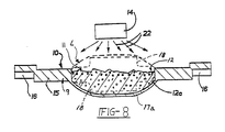
- the cylindrical surface 12a of the cavity 12 receives the molten metal deposit 11 sprayed thereon from a plasma spray nozzle 14 (schematically depicted).
- the spray cast deposit 11 is built up above the cavity 12 to a level L (see phantom line in Fig. 1) such that the hub 18, Figs. 2 and 3, can be machined from the deposit.
- the dish-shaped component 9 of Fig. 8 includes a downwardly bowed or arcuate, removable bottom wall 17a to receive sufficient spray cast metal 11 to be machined into a central hub 18 (see phantom lines) extending axially on opposite sides of the rim section 15.
- the invention envisions forming a metallurgical diffusion bond joint J, Fig. 2, of enhanced structural integrity between the metal substrate 10 (or bladed component 9) and the spray cast metal 11.
- a metallurgical diffusion bond joint is a continuous metallic structure of comingled atoms across the interface of the substrate 10 and the spray cast metal 11 being joined. The presence of epitaxial grain growth across the interface is considered to evidence a preferred, optimized metallurgical diffusion bond joint and to infer that the substrate surface 12a is atomically clean just prior to spraying of the spray cast metal 11 thereon.
- Figs. 2 and 3 the spray cast metal deposit 11 is shown machined to form the hub 18 of the gas turbine rotor 20.
- An axially-extending passage (not shown) may be ultimately machined in the hub 18 to receive the drive shaft of the gas turbine engine in known manner.
- the formation of a diffusion bond joint J of enhanced structural integrity between the surface 12a of the metal substrate 10 and the spray cast metal 11 is effected by applying one or more surface treatments (to be described) to the surface 12a of the cavity 12 in proper sequence with spray casting of the molten metal 11 thereon and subsequent hot isostatic pressing of the substrate and spray cast deposit.
- the intent of the surface treatments is to reduce and possibly eliminate the presence of certain tramp elements, such as S, Si, O, P, etc. in a substrate surface layer to hinder or prevent migration of such tramp elements to the substrate surface 12a and to the subsequently formed bond joint J during preheating of the substrate 10 prior to spray casting and during subsequent heating cycles.
- the invention involves the discovery that in structural spray cast articles made prior to this invention, such tramp elements were present at the bond joint J (as verified by Auger electron surface analysis) and adversely affected the bond joint structural integrity as measured by mechanical properties, specifically elevated temperature stress rupture properties.
- the surface treatments of the present invention used to minimize the presence of these undesirable elements at the substrate surface 12a and at the diffusion bond joint J to enhance the bond joint integrity include the following:
- the present invention involves the further discovery that different surface treatments have different effects on bond joint structural integrity depending upon the similarity or dissimilarity of the compositions of the substrate metal and the spray cast metal.
- the vacuum cleaning treatment alone, has been found to substantially enhance the structural integrity of the bond joint as illustrated in the examples set forth hereinbelow.
- the boronizing/heating treatment with or without knurling, but with development of the exposed molten layer has been found to substantially enhance the structural integrity of the bond joint as illustrated in the examples set forth hereinbelow.
- the molten metal is sprayed onto the surface 12a of the solid (e.g., cast) metal substrate 10 after the surface 12a is subjected to one or more of the aforementioned surface treatments (a)-(d) referred to hereinabove depending upon the compositional similarities or dissimilarities between the substrate and the spray cast deposit, and after preheating and cleaning of the surface 12a as described hereinbelow.
- a plasma spray nozzle 14 for projecting sprayed molten metal (represented by arrows 22) onto surface 12a of the cavity 12.
- the molten metal 22 is sprayed by means of the introduction of metal powder (e.g., -325 mesh) into a high velocity thermal plasma.
- metal powder e.g., -325 mesh
- Such an apparatus generates a high temperature plasma of flowing inert gas. Solid metal powder is injected into and fully or partially melted by the high temperature plasma and the resulting fully or partially molten droplets/particles are projected, by movement of the plasma, toward the substrate surface 12a that is prepared to receive them.
- the solid metal substrate 10 may be moved and/or the plasma gun indexed in order to impart a configuration to the deposited metal appropriate for the particular application.
- the spray cast metal 11 is adherent to the substrate surface 12a to form a preform comprising the spray cast metal 11 deposited and incrementally solidified onto the solid metal substrate 10.
- An as-sprayed metallurgical diffusion bond is formed between the substrate 10 and the spray cast deposit 11 as well as throughout the spray cast deposit 11.
- the nozzle 14 is in a fixed position with respect to the cavity 12 and the substrate 10 is rotated with respect to the nozzle 14 to deposit the metal 11 within and above the cavity 12 in the appropriate configuration (e.g., to level L).
- the cavity 12 receiving the molten metal 22 has an irregular configuration, it may be necessary to move both the solid metal substrate 10 as well as the nozzle 14 in order to minimize the formation of voids at the interface between the surface 12a and the spray cast metal 11.
- the process is conducted with a controlled inert atmosphere (e.g., Ar and He)
- the surface 12a of the cavity 12 and the surface of the spray cast deposit 11 should be free of surface contamination.
- a subsequent hot isostatic pressing operation is used to close any minor voids at the interface, fully densify the deposit 11 and enhance the as-sprayed metallurgical diffusion bond joint between the spray cast deposit 11 and the solid metal substrate 10.
- the substrate 10 prior to low pressure, high velocity spray casting in the spray chamber, is preheated in the spray chamber in a controlled, low pressure atmosphere (Ar and He) by impingement with a thermal plasma and the substrate surface 12a is then immediately reverse arc cleaned (RAC'ed) in a thermal plasma.
- Preheating of the solid metal substrate affects the rate of heat transfer when the molten metal spray subsequently strikes the substrate surface 12a on which it is deposited. Because steep thermal gradients between the spray cast deposit and the substrate can result in residual stresses across their interface, the amount of preheating is controlled to minimize such gradients.
- preheating the solid metal substrate to a temperature in the range of from 1093°C to 1204°C is preferred.
- the solid metal substrate 10 can be preheated by means of the thermal plasma or other means (e.g., induction heating) prior to the deposition of the spray cast metal 11, thereby providing an efficient production process capable of being automated.
- the spray chamber (not shown) receiving the substrate 10 is typically first evacuated to about 0.13 - 2 MPa, and then backfilled to 4 103 - 6.6 103 MPa with Ar and He.
- the substrate 10 is then preheated to a desired preheat temperature by impinging a thermal plasma generated by the nozzle 14 on the surface 12a.
- Reverse arc cleaning (RAC) is carried out generally by maintaining the arc at about 100-250 A between the spray nozzle gun (anode) and the substrate surface (cathode) 12a at a chamber pressure in the range of about 30 to about 9.3 103 MPa Both preheating and reverse arc cleaning are conducted in the controlled atmosphere of argon and helium.
- the substrate surface 12a can be preheated and then reverse arc cleaned (RAC) in multiple sequences prior to spray casting. However, only the final reverse arc clean (RAC) step (just prior to the onset of spray casting) should be allowed to form the exposed in-situ molten phase or layer when the substrate is boronized.
- the time of RAC can be used to control cleaning of the substrate surface 12a and uniformity of the molten layer formed.
- the molten metal sprayed onto the substrate surface 12a is rapidly solidified because of the temperature differential between the sprayed molten metal and the solid metal substrate 10 even when the solid metal substrate 10 is preheated. This affords the opportunity to control the microstructure of the spray cast metal 11.
- the grain size of the spray cast metal 11 can be varied and controlled.
- the molten metal solidifies incrementally to the solid metal substrate 10 and then to the previously deposited solidified spray cast metal 11 to build up the spray cast metal deposit on the substrate 10.
- the spray cast metal 11 is subsequently rendered fully dense with a desired fine grain size (e.g., in the range of from ASTM 4 to ASTM 10) by appropriate thermal treatments.
- a desired fine grain size e.g., in the range of from ASTM 4 to ASTM 10.
- the preform thusly formed is hot isostatically pressed to virtually eliminate any voids in the spray cast metal 11 and metallurgically diffusion bond the spray cast metal 11 and the surface 12a of the solid metal substrate 10.
- Hot isostatic pressing is preferably conducted in such a manner as to promote epitaxial grain growth across the interfacial bond region between the substrate surface 12a and the spray cast metal 11.
- hot isostatic pressing is carried out under gas pressure thereby applying an isostatic pressure on the preform.
- the preform can be heat treated to obtain the desired mechanical properties for both the spray cast metal 11 and the solid metal substrate 10.
- the process of the invention includes the formation during the final stages of spray casting of a gas impervious layer on the outermost surface (i.e., uppermost surface in Fig. 1) of the spray cast metal 11 to allow removal of residual microporosity by the subsequent hot isostatic pressing treatment.
- the gas impervious layer provides a means of transmitting the gas pressure during hot isostatic pressing to densify the spray cast metal 11 and eliminate any residual voids therein.
- the present invention is practiced with isostatic pressures of 103 to 172 MPa at temperatures of between about 1065°C to about 1232°C for about 2 to about 4 hours when the substrate and the spray cast metal are typical nickel base superalloys.
- the invention involves the discovery that the different surface treatments (a)-(d) described hereinabove have different effects on the structural integrity of structural spray cast articles depending upon the similarity or dissimilarity of the compositions of the substrate metal 10 and the spray cast metal 11.
- a set of preliminary tests was conducted to spray cast low carbon Astroloy (LC Astroloy) nickel base superalloy onto an investment cast Mar-M247 nickel base superalloy substrate as representative of dissimilar compositions.
- Another set of preliminary tests was conducted to spray cast LC Astroloy onto a LC Astroloy substrate as representative of the same or similar compositions.
- the LC Astroloy substrate itself had been spray cast and hot isostatically pressed under the same spraying and pressing conditions as described hereinafter for the specimens.
- the investment cast Mar-M247 substrate comprised a generally flat, square plate of nominal 5 cm width, 5 cm length and 1.9 cm tickness.
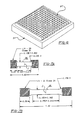
- a knurled specimen plate P is shown in Fig. 6
- the substrate surface 12a typically was solvent cleaned (e.g., using 1,1,1-trichloroethane and then Freon solvent) prior to vacuum cleaning and/or boronizing.
- the LC Astroloy was spray cast to a thickness of about 1.9 cm onto the Mar-M247 substrate plate as it was rotated with the nozzle 14 perpendicular to the substrate plate.
- the spray gun was translated relative to the rotating substrate to insure build-up of a uniform deposit in the cavity 12.
- the specimen plate Prior to molten metal spraying, the specimen plate was low pressure plasma preheated (LPP) with the plasma gun at a chamber pressure of about 5.3 103 MPa (Ar and He) with a gun power of approximately 70 KW until a surface temperature of 538°C. was observed as indicated by the pyrometer. Then, the preheated specimen plate was low temperature reverse arc cleaned (LT RAC) at 538°C at about 125 A until clean. For specimens that were previously boronized, no molten layer was formed during the LT RAC.
- LPP low pressure plasma preheated
- LT RAC low temperature reverse arc cleaned
- the LPP preheat of the specimen plate was continued at 6.6 103 MPa until the temperature of the plate surface was about 1182°C.
- high temperature reverse arc clean (HT RAC) was initiated.
- the HT RAC was maintained until the surface was observed to be clean (e.g., substantially free of any oxides formed during preheating) and a uniform molten surface layer was observed thereon.
- the HT RAC treatment provides the required surface energy input to clean the specimen and, if it is boronized, to also melt the boronized surface layer.
- the HT RAC was turned off and powder feeding into the existing plasma plume was immediately started to impinge fully molten droplets on the plate surface with a spray chamber pressure of about 10 microns or less. A zero time lag between HT RAC "off” and powder feed "on” is desired.
- the plate was cooled under a vacuum of less than 10 microns.
- the chamber was then argon backfilled to atmosphere prior to specimen removal.
- the spray cast preforms were hot isostatically pressed at 1185°C and 172 MPa for 4 hours. Thereafter, the preforms were heat treated as follows: 1115°C for 2 hours/AC (air cool) + 871°C for 8 hours/AC + 982°C for 4 hours/AC + 648°C for 24 hours/AC + 760°C for 8 hours/AC to ambient temperature.
- Table I sets forth 760°C/552 MPa stress rupture test results for the surface treatments (a)-(d) of the invention described hereinabove for the aforementioned dissimilar compositions.
- the configuration of the stress rupture specimens is shown in Fig. 7A.
- the stress rupture specimens are machined from the center of the spray cast plates P with the longitudinal axis of the stress rupture specimens normal to the plate surface such that the diffusion bond joint is normal to the longitudinal axis of the stress rupture specimens (e.g., see Fig. 7A), and centered in the gage section.
- the Group I specimens involved only vapor honing of the substrate surface 12a using commercially available alumina grit prior to preheating and reverse arc cleaning.
- the Group II specimens were vacuum cleaned in accordance with surface treatment (a) set forth above (e.g., vacuum level of at least 1.33 10 ⁇ 2 MPa for 3 hours at 1177°C.
- the specimens of Groups II and IV were boronized in accordance with surface treatment (b) set forth above; e.g., 0.6 mg/cm2 to 2.6 mg/cm2 boron was applied to the substrate surface 12a by Materials Development Corp., Medford, Massachusetts to yield a diffused boron enriched surface layer at the substrate surface 12a.
- the Group IV specimens were heated sufficiently to form a uniform exposed molten layer on the substrate surface at the onset of spray casting whereas the Group III specimens were not so heated and did not develop the uniform exposed molten layer.
- the specimens of Group V were treated similarly to the Group IV specimens but the substrate surface was knurled prior to being boronized; e.g., the specimens had a 0.10 cm ⁇ 0.10 cm ⁇ 0.10 cm pyramidal knurl pattern, Fig. 6.
- Specimens of Groups VI and VII were both vacuum cleaned and boronized in accordance with the surface treatments (a) and (b) set forth above. However, the Group VI specimens were heated sufficiently to form the exposed molten layer on the substrate surface at the onset of spray casting whereas the Group VII specimens were not so heated.
- each dish specimen D was positioned on a rotatable table with the sidewall S of the dish specimen extending vertically such that the cavity C could receive the spray cast deposit of LC Astroloy.
- Spray casting of the LC Astroloy was conducted using a spray gun oriented at 44 degrees to the dish side walls and at 46 degrees to the horizontal bottom and top lip of the dish specimen while the table was rotated. The spray gun was translated relative to the rotating dish specimen to insure build-up of a uniform deposit. All of the dish specimens were subjected to the vacuum cleaning treatment (a) and boronizing treatment (b) described above prior to placement in the spray chamber.
- the dish specimens were subjected to low pressure plasma preheat (LPP), low temperature reverse clean (LTRAC) and high temperature reverse arc clean (HTRAC) procedures as described hereinabove for the plate specimens with care taken to insure a desired uniform temperature from the top to the bottom of the sidewall S during spray casting.
- LPP low pressure plasma preheat
- LTRAC low temperature reverse clean
- HTRAC high temperature reverse arc clean
- Table II sets forth stress rupture properties for the dish specimens.
- the stress rupture specimens shown in Fig. 7B were machined radially from the dish specimens D with the longitudinal axis of the stress rupture specimens coaxial to the axis of one of the large or small pins R,R′ adjacent the top or bottom of the sidewall S such that bond joint J was normal to the longitudinal axis of the stress rupture specimen.
- Table III reveals the results of 760°C/551 MPa stress rupture tests of stress rupture specimens, Fig. 7B, machined from LC Astroloy/IN713LC dish specimens where LC Astroloy was spray cast in an IN713LC dish specimen, Fig. 5 which had been vacuum cleaned, boronized, preheated and HT RAC'ed to develop a molten layer at the onset of spray casting as explained hereinabove. After spray casting, these dish specimens were hot isostatically pressed at 1228°C at 103 MPa for 4 hours and then heat treated as described hereinabove for the plate specimens of Table I.
- the presence of epitaxial grain growth across the diffusion bond joint after HIP is preferred to further enhance bond structural integrity as evidenced by parent metal failures in the stress rupture tests.
- the substrate comprised a flat, square plate of nominal 5 cm width, length and 1.9 cm thickness.
- the LC Astroloy substrate plate was formed by spray casting and hot isostatic pressing, but not bonding to any other substrate, under the same conditions as described hereinafter for the specimens. Specimens were prepared to investigate the effect of vacuum cleaning of the substrate surface on the structural integrity of the bond joint of the structural spray cast specimen.
- the vacuum cleaning treatment (as well as preheating and reverse arc cleaning) used to prepare the specimens was similar to that set forth above for the plate specimens of dissimilar composition.
- the vacuum cleaned specimens were compared against similar specimens which were vapor honed prior to preheating and reverse arc cleaning.
- the LC Astroloy was spray cast onto the LC Astroloy substrate plate to a thickness of about 1.9 cm using the same technique employed for spray casting the Mar-M247 on LC Astroloy.
- the spray cast preforms were hot isostatically pressed at 1185°C and 172 MPa hours. Thereafter, the preforms were subjected to the same heat treatment described above for the plate specimens of dissimilar composition.
- Table IV sets forth 760°C/551 MPa rupture test results for the surface treatments investigated.
- the configuration of the stress rupture specimens is shown in Fig. 7A.
- Table IV demonstrates that the structural integrity of the bond joint between similar compositions of the substrate metal and the spray cast deposit can be enhanced by applying the vacuum cleaning surface treatment to the substrate surface prior to metal spray casting.
- the improvement with the vacuum cleaning treatment alone is believed to be due to the removal from the plate surface of certain tramp elements (mentioned hereinabove) which are deleterious to formation of a satisfactory metallurgical diffusion bond joint; i.e., a metallurgical diffusion bond joint which does not exhibit failure solely along the joint.
- the enhancement of diffusion bond joint integrity of structural spray cast articles as measured by stress rupture tests can be significantly improved by the application of the above discussed surface treatment processes (a)-(d) to the substrate 10 prior to deposition of the spray cast metal 11 and metallurgical diffusion bonding.
- the invention recognizes that the compositional difference between the materials of the substrate and the spray cast will impact the surface treatment processes necessary to enhance the bond joint integrity.
Applications Claiming Priority (2)
| Application Number | Priority Date | Filing Date | Title |
|---|---|---|---|
| US45295889A | 1989-12-19 | 1989-12-19 | |
| US452958 | 1989-12-19 |
Publications (1)
| Publication Number | Publication Date |
|---|---|
| EP0434580A2 true EP0434580A2 (fr) | 1991-06-26 |
Family
ID=23798659
Family Applications (1)
| Application Number | Title | Priority Date | Filing Date |
|---|---|---|---|
| EP90420551A Withdrawn EP0434580A2 (fr) | 1989-12-19 | 1990-12-17 | MÀ©thode de renforcement de l'intégrité structurelle d'un point d'un article coulé par pulvérisation |
Country Status (4)
| Country | Link |
|---|---|
| US (1) | US5318217A (fr) |
| EP (1) | EP0434580A2 (fr) |
| JP (1) | JPH06212389A (fr) |
| CA (1) | CA2030427A1 (fr) |
Cited By (3)
| Publication number | Priority date | Publication date | Assignee | Title |
|---|---|---|---|---|
| EP1995344A1 (fr) * | 2007-05-25 | 2008-11-26 | InnCoa GmbH | Revêtement doté d'une gestion ultérieure par diffusion |
| FR2967693A1 (fr) * | 2010-11-19 | 2012-05-25 | Peugeot Citroen Automobiles Sa | Procede pour l'application d'un revetement sur un carter cylindre en alliage d'aluminium |
| US9724780B2 (en) | 2014-06-05 | 2017-08-08 | Honeywell International Inc. | Dual alloy turbine rotors and methods for manufacturing the same |
Families Citing this family (18)
| Publication number | Priority date | Publication date | Assignee | Title |
|---|---|---|---|---|
| US7043819B1 (en) * | 1996-12-23 | 2006-05-16 | Recast Airfoil Group | Methods for forming metal parts having superior surface characteristics |
| US20030088980A1 (en) * | 1993-11-01 | 2003-05-15 | Arnold James E. | Method for correcting defects in a workpiece |
| US5525429A (en) * | 1995-03-06 | 1996-06-11 | General Electric Company | Laser shock peening surface enhancement for gas turbine engine high strength rotor alloy repair |
| US5732467A (en) * | 1996-11-14 | 1998-03-31 | General Electric Company | Method of repairing directionally solidified and single crystal alloy parts |
| US20040018299A1 (en) * | 1996-12-23 | 2004-01-29 | Arnold James E. | Method of forming a diffusion coating on the surface of a workpiece |
| US6331361B1 (en) * | 1998-11-19 | 2001-12-18 | Hickham Industries, Inc. | Methods for manufacture and repair and resulting components with directionally solidified or single crystal materials |
| US6510694B2 (en) | 2000-07-10 | 2003-01-28 | Lockheed Corp | Net molded tantalum carbide rocket nozzle throat |
| US6464129B2 (en) * | 2000-12-22 | 2002-10-15 | Triumph Group, Inc. | Method of diffusion bonding superalloy components |
| US6805971B2 (en) | 2002-05-02 | 2004-10-19 | George E. Talia | Method of making coatings comprising an intermetallic compound and coatings made therewith |
| US6984358B2 (en) * | 2002-09-13 | 2006-01-10 | Lockheed Martin Corporation | Diffusion bonding process of two-phase metal alloys |
| US6935006B2 (en) * | 2002-12-18 | 2005-08-30 | Honeywell International, Inc. | Spun metal form used to manufacture dual alloy turbine wheel |
| US20050241147A1 (en) * | 2004-05-03 | 2005-11-03 | Arnold James E | Method for repairing a cold section component of a gas turbine engine |
| US7259350B2 (en) * | 2004-08-26 | 2007-08-21 | United Technologies Corporation | Turbine component crack repair using cathodic arc and/or low pressure plasma spraying and HIP |
| EP1772228A1 (fr) * | 2005-10-07 | 2007-04-11 | Siemens Aktiengesellschaft | Procédé pour la réparation d'une pièce à microstructure orientée. |
| DE102006057912A1 (de) * | 2006-12-08 | 2008-06-12 | Mtu Aero Engines Gmbh | Leitschaufelkranz sowie Verfahren zum Herstellen desselben |
| ES2706986T3 (es) * | 2012-03-28 | 2019-04-02 | Alfa Laval Corp Ab | Nuevo concepto de soldadura fuerte |
| DE102017009948A1 (de) * | 2017-10-26 | 2019-05-02 | Forschungszentrum Jülich GmbH Fachbereich Patente | Verfahren zur Reparatur einkristalliner Werkstoffe |
| KR102655542B1 (ko) * | 2019-09-13 | 2024-04-09 | 프랙스에어 에스.티. 테크놀로지, 인코포레이티드 | 증가된 결정질의 조밀한 개선된 코팅의 생성 방법 |
Family Cites Families (14)
| Publication number | Priority date | Publication date | Assignee | Title |
|---|---|---|---|---|
| US3839618A (en) * | 1972-01-03 | 1974-10-01 | Geotel Inc | Method and apparatus for effecting high-energy dynamic coating of substrates |
| US4008052A (en) * | 1975-04-30 | 1977-02-15 | Trw Inc. | Method for improving metallurgical bond in bimetallic castings |
| US4096615A (en) * | 1977-05-31 | 1978-06-27 | General Motors Corporation | Turbine rotor fabrication |
| US4270256A (en) * | 1979-06-06 | 1981-06-02 | General Motors Corporation | Manufacture of composite turbine rotors |
| US4335997A (en) * | 1980-01-16 | 1982-06-22 | General Motors Corporation | Stress resistant hybrid radial turbine wheel |
| US4581300A (en) * | 1980-06-23 | 1986-04-08 | The Garrett Corporation | Dual alloy turbine wheels |
| US4418124A (en) * | 1980-10-06 | 1983-11-29 | General Electric Company | Plasma spray-cast components |
| US4447466A (en) * | 1981-08-14 | 1984-05-08 | General Electric Company | Process for making plasma spray-cast components using segmented mandrels |
| US4562090A (en) * | 1983-11-30 | 1985-12-31 | Gray Tool Company | Method for improving the density, strength and bonding of coatings |
| DE3422718A1 (de) * | 1984-06-19 | 1986-01-09 | Plasmainvent AG, Zug | Vakuum-plasma-beschichtungsanlage |
| US4529452A (en) * | 1984-07-30 | 1985-07-16 | United Technologies Corporation | Process for fabricating multi-alloy components |
| US4659288A (en) * | 1984-12-10 | 1987-04-21 | The Garrett Corporation | Dual alloy radial turbine rotor with hub material exposed in saddle regions of blade ring |
| US4705203A (en) * | 1986-08-04 | 1987-11-10 | United Technologies Corporation | Repair of surface defects in superalloy articles |
| US4878953A (en) * | 1988-01-13 | 1989-11-07 | Metallurgical Industries, Inc. | Method of refurbishing cast gas turbine engine components and refurbished component |
-
1990
- 1990-11-21 CA CA002030427A patent/CA2030427A1/fr not_active Abandoned
- 1990-12-17 EP EP90420551A patent/EP0434580A2/fr not_active Withdrawn
- 1990-12-18 JP JP2417862A patent/JPH06212389A/ja active Pending
-
1991
- 1991-11-14 US US07/794,320 patent/US5318217A/en not_active Expired - Fee Related
Cited By (4)
| Publication number | Priority date | Publication date | Assignee | Title |
|---|---|---|---|---|
| EP1995344A1 (fr) * | 2007-05-25 | 2008-11-26 | InnCoa GmbH | Revêtement doté d'une gestion ultérieure par diffusion |
| FR2967693A1 (fr) * | 2010-11-19 | 2012-05-25 | Peugeot Citroen Automobiles Sa | Procede pour l'application d'un revetement sur un carter cylindre en alliage d'aluminium |
| US9724780B2 (en) | 2014-06-05 | 2017-08-08 | Honeywell International Inc. | Dual alloy turbine rotors and methods for manufacturing the same |
| US10399176B2 (en) | 2014-06-05 | 2019-09-03 | Honeywell International Inc. | Dual alloy turbine rotors and methods for manufacturing the same |
Also Published As
| Publication number | Publication date |
|---|---|
| JPH06212389A (ja) | 1994-08-02 |
| US5318217A (en) | 1994-06-07 |
| CA2030427A1 (fr) | 1991-06-20 |
Similar Documents
| Publication | Publication Date | Title |
|---|---|---|
| US5318217A (en) | Method of enhancing bond joint structural integrity of spray cast article | |
| US5273708A (en) | Method of making a dual alloy article | |
| US4921405A (en) | Dual structure turbine blade | |
| US8206117B2 (en) | Turbine components and methods of manufacturing turbine components | |
| US6355086B2 (en) | Method and apparatus for making components by direct laser processing | |
| US4851188A (en) | Method for making a turbine blade having a wear resistant layer sintered to the blade tip surface | |
| US9457531B2 (en) | Bi-cast turbine rotor disks and methods of forming same | |
| EP1478482B1 (fr) | Procede de suppression de defauts de moulage | |
| CA1138170A (fr) | Faconnage de pieces de precision | |
| US7479299B2 (en) | Methods of forming high strength coatings | |
| US8956478B2 (en) | Process for joining refractory ceramic parts by spark plasma sintering (SPS) | |
| US4418124A (en) | Plasma spray-cast components | |
| EP2278045A1 (fr) | methods de rénovation de cibles de pulvérisation en tantale et cibles rénovées | |
| EP2692464A2 (fr) | Composants d'aluminure de titane et procédés de fabrication desdits composants à partir d'articles formés par un processus de consolidation | |
| US5273204A (en) | Method for joining materials by metal spraying | |
| Das et al. | Direct laser fabrication of superalloy cermet abrasive turbine blade tips | |
| US4447466A (en) | Process for making plasma spray-cast components using segmented mandrels | |
| US5312650A (en) | Method of forming a composite article by metal spraying | |
| RU2619419C2 (ru) | Способ нанесения алюминида титана и изделие с поверхностью из алюминида титана | |
| JP2001232447A (ja) | 陰極および陰極アーク堆積用陰極の製造法 | |
| US4690875A (en) | High vacuum cast ingots | |
| US20040126266A1 (en) | Method for manufacturing composite articles and the articles obtained therefrom | |
| JPH02277760A (ja) | ニッケル又はコバルトを基礎とする保護層を有する構成部材及びその製造方法 | |
| VerSnyder | Keynote Lecture Superalloy Technology-Today and Tomorrow | |
| JPH11335801A (ja) | スプレ―形成法により形成され熱処理された超合金物体及び該超合金物体の製造方法 |
Legal Events
| Date | Code | Title | Description |
|---|---|---|---|
| PUAI | Public reference made under article 153(3) epc to a published international application that has entered the european phase |
Free format text: ORIGINAL CODE: 0009012 |
|
| AK | Designated contracting states |
Kind code of ref document: A2 Designated state(s): DE FR GB |
|
| STAA | Information on the status of an ep patent application or granted ep patent |
Free format text: STATUS: THE APPLICATION HAS BEEN WITHDRAWN |
|
| 18W | Application withdrawn |
Withdrawal date: 19920118 |
|
| R18W | Application withdrawn (corrected) |
Effective date: 19920118 |