EP0433852B1 - Gitter für die Osteosynthese oder zum Befestigen von künstlichen Körperteilen - Google Patents
Gitter für die Osteosynthese oder zum Befestigen von künstlichen Körperteilen Download PDFInfo
- Publication number
- EP0433852B1 EP0433852B1 EP90123827A EP90123827A EP0433852B1 EP 0433852 B1 EP0433852 B1 EP 0433852B1 EP 90123827 A EP90123827 A EP 90123827A EP 90123827 A EP90123827 A EP 90123827A EP 0433852 B1 EP0433852 B1 EP 0433852B1
- Authority
- EP
- European Patent Office
- Prior art keywords
- grid
- bone
- webs
- holes
- osteosynthesis
- Prior art date
- Legal status (The legal status is an assumption and is not a legal conclusion. Google has not performed a legal analysis and makes no representation as to the accuracy of the status listed.)
- Revoked
Links
Images


Classifications
-
- A—HUMAN NECESSITIES
- A61—MEDICAL OR VETERINARY SCIENCE; HYGIENE
- A61B—DIAGNOSIS; SURGERY; IDENTIFICATION
- A61B17/00—Surgical instruments, devices or methods
- A61B17/56—Surgical instruments or methods for treatment of bones or joints; Devices specially adapted therefor
- A61B17/58—Surgical instruments or methods for treatment of bones or joints; Devices specially adapted therefor for osteosynthesis, e.g. bone plates, screws or setting implements
- A61B17/68—Internal fixation devices, including fasteners and spinal fixators, even if a part thereof projects from the skin
- A61B17/80—Cortical plates, i.e. bone plates; Instruments for holding or positioning cortical plates, or for compressing bones attached to cortical plates
- A61B17/8085—Cortical plates, i.e. bone plates; Instruments for holding or positioning cortical plates, or for compressing bones attached to cortical plates with pliable or malleable elements or having a mesh-like structure, e.g. small strips
-
- A—HUMAN NECESSITIES
- A61—MEDICAL OR VETERINARY SCIENCE; HYGIENE
- A61F—FILTERS IMPLANTABLE INTO BLOOD VESSELS; PROSTHESES; DEVICES PROVIDING PATENCY TO, OR PREVENTING COLLAPSING OF, TUBULAR STRUCTURES OF THE BODY, e.g. STENTS; ORTHOPAEDIC, NURSING OR CONTRACEPTIVE DEVICES; FOMENTATION; TREATMENT OR PROTECTION OF EYES OR EARS; BANDAGES, DRESSINGS OR ABSORBENT PADS; FIRST-AID KITS
- A61F2/00—Filters implantable into blood vessels; Prostheses, i.e. artificial substitutes or replacements for parts of the body; Appliances for connecting them with the body; Devices providing patency to, or preventing collapsing of, tubular structures of the body, e.g. stents
-
- A—HUMAN NECESSITIES
- A61—MEDICAL OR VETERINARY SCIENCE; HYGIENE
- A61F—FILTERS IMPLANTABLE INTO BLOOD VESSELS; PROSTHESES; DEVICES PROVIDING PATENCY TO, OR PREVENTING COLLAPSING OF, TUBULAR STRUCTURES OF THE BODY, e.g. STENTS; ORTHOPAEDIC, NURSING OR CONTRACEPTIVE DEVICES; FOMENTATION; TREATMENT OR PROTECTION OF EYES OR EARS; BANDAGES, DRESSINGS OR ABSORBENT PADS; FIRST-AID KITS
- A61F2/00—Filters implantable into blood vessels; Prostheses, i.e. artificial substitutes or replacements for parts of the body; Appliances for connecting them with the body; Devices providing patency to, or preventing collapsing of, tubular structures of the body, e.g. stents
- A61F2/02—Prostheses implantable into the body
- A61F2/30—Joints
- A61F2/30721—Accessories
- A61F2/30749—Fixation appliances for connecting prostheses to the body
-
- A—HUMAN NECESSITIES
- A61—MEDICAL OR VETERINARY SCIENCE; HYGIENE
- A61F—FILTERS IMPLANTABLE INTO BLOOD VESSELS; PROSTHESES; DEVICES PROVIDING PATENCY TO, OR PREVENTING COLLAPSING OF, TUBULAR STRUCTURES OF THE BODY, e.g. STENTS; ORTHOPAEDIC, NURSING OR CONTRACEPTIVE DEVICES; FOMENTATION; TREATMENT OR PROTECTION OF EYES OR EARS; BANDAGES, DRESSINGS OR ABSORBENT PADS; FIRST-AID KITS
- A61F2220/00—Fixations or connections for prostheses classified in groups A61F2/00 - A61F2/26 or A61F2/82 or A61F9/00 or A61F11/00 or subgroups thereof
- A61F2220/0008—Fixation appliances for connecting prostheses to the body
Definitions
- the invention relates to a grid for osteosynthesis or for attaching artificial body parts with the features of the preamble of claim 1.
- Osteosynthesis is the operative connection of the end points of a broken bone using mechanical aids.
- fixation In the case of fractures (fractures) and osteotomies (surgical cutting of a bone), particularly in the area of the human skull, a so-called fixation is necessary, i.e. a firm positioning of the fragments to each other.
- wire seams are therefore only rarely used and for small fragments, but where threading is required is extremely difficult and often leads to complete denudation of the bone, ie an undesirable removal of the periosteum.
- Known plate systems for osteosynthesis have brought improvements over the wire seam, but they also have disadvantages.
- the fracture must be exposed and prepared relatively extensively, which delays the healing process.
- Known plate systems also have the disadvantage that the bone fragments are essentially stabilized only two-dimensionally. However, if several large-area plates are used, the soft tissues that lie above the plates are also kept away from the bone, which can also hinder the healing process.
- the known plate systems also have the disadvantage that they can only be adapted to the bone structure with great effort. If this adjustment does not succeed exactly, there is a risk of the bone parts being distorted.
- DE-U-88 07 909 describes a bone plate for osteosynthesis with grids for anchoring the plate, in which elongated webs are provided between individual screw hole mounts. However, free-standing bars such as arms reach outwards and no bars are provided between outside screw holes.
- the affected bone surface Before the osteosynthesis material described above is attached to the bone by means of screws or the like, the affected bone surface must be exposed. As a result of this denusion of the bone, the vascular supply to the affected bone parts is interrupted, which can lead to a flat breakdown of bone material in the denuded area until the vascular supply is restored due to the natural healing process.
- the prior art can be improved in that the surgeon should be given the opportunity to expose the bone surface as little as possible.
- the osteosynthesis material should only cover a relatively small area of the bone so that the vascular supply can be produced as quickly and as extensively as possible during the healing process. Bone degradation under the osteosynthesis material should be avoided as much as possible.
- the present invention has for its object to provide a grid for osteosynthesis and for attaching artificial body parts, such as epitheses, which on the one hand enables a favorable course of bone healing and on the other hand a high three-dimensional stability of the system of grid, bone and screws.
- this object is achieved in that the connecting line of the center points of any two holes of the lattice lies within the outer border of the lattice and that the lattice does not cover more than 45% of the bone occupied by it.
- the grid according to the invention is preferably designed such that the connecting line of any two adjacent holes that lie at the edge of the grid is in each case the center line of a web.
- the invention is based on the knowledge that the surgeon can then achieve optimum results with regard to the stability of the system and at the same time with regard to the healing process if, on the one hand, to promote the three-dimensional stability of the grid, the connecting line of all possible pairs of holes in the grid is in each case within the outer border of the grid and on the other hand the bone coverage is as low as possible.
- the grid according to the invention can be prepared on site by the surgeon in order to adapt it to the requirements of the individual case.
- the surgeon can cut the grid so that a web remains between two edge holes, leaving a two-dimensional piece of grid from which, if necessary, extending arms protrude. If this two-dimensional structure, which is stabilized at its edges by webs, is screwed to the bone, a three-dimensional stable structure is created overall.
- the invention thus relates to a tradable product which is designed in such a way that it can be modified in many ways by simple manipulations on site in accordance with the requirements of the individual case.
- the invention therefore provides a delicate web construction, with the stiffening and stability being achieved by means of narrow webs.
- a lattice-like structure can be easily adapted to the individual bone structure and nevertheless provides good three-dimensional stability, in particular if screws at the corners of a square formed by the lattice are screwed through the holes in the bone.
- the fine webs at least partially each have a length of more than 4 mm and a width of less than 1.5 mm, preferably less than 1 mm.
- the webs at least partially have a length of more than 5 mm, wherein they have the widths indicated above over this entire length.
- a particularly extensive freedom of design is given to the surgeon when the grids according to the invention have different web structures, i.e. Lengths of the webs and their geometric arrangements are provided so that the grids can be optimally adapted to the given problem either by removing certain parts on site.
- the grid for osteosynthesis according to the invention has the advantage over conventional plate systems that the stability of the fixation is essentially determined by the shape of the grid, but not by the thickness or length of the plate.
- the invention Grid can be designed so that it can be easily adapted to the required geometry of the osteosynthesis. It is flexible and only becomes stable after screwing due to the three-dimensional stiffening. Intermaxillary fixation is not required.
- the grid according to the invention has the advantage that excessive denudation (exposure) of the bone can be avoided.
- the lattice according to the invention is attached, only relatively little periosteum needs to be removed. Since the periost (connective tissue skin layer around the bone) ensures the renewal of bone (endosteal ossification) through the supply of nutrients to the bone, which ensures lifelong bone renewal, the healing process can take place more quickly and less prone to malfunctions in an osteosynthesis according to the invention.
- a grid according to the invention can be placed parallel to the fracture, the periosteum must be pushed off in the immediate vicinity of the fracture or osteotomy gap. This fact also enables a better blood supply to the fragments and thus a better healing process when using a grid according to the invention.
- a grid according to the invention enables individual adaptation to extremely complicated geometric requirements due to the break. If the grid according to the invention is provided, for example, in pieces of 6 x 6 cm edge length, the surgeon can cut out desired pieces on site from such a grid piece depending on the osteotomy or the course of the fracture. Particularly in the case of broken fragments, small fragments with individual, individually bent finger projections can be easily fixed in this way. The fragments do not need to be fixed with additional wire seams and denudation can also be largely avoided.
- gratings according to the invention also have the advantage that large areas of tissue do not have to be exposed when they are attached. Therefore, the subsequent removal of a grating according to the invention from the break point is relatively simple and can even be carried out under local anesthesia. Even when the grille is removed, only the former operating area has to be exposed slightly.
- the delicate grid according to the invention has the advantage of not being applied. This is both medically and aesthetically advantageous.
- a variant of the invention relates to the attachment of epitheses, in particular in the area of the human face, instead of osteosynthesis.
- the grid according to the invention described in the claims is also suitable for this purpose.
- aids such as glasses or a prosthesis are generally used to fasten epitheses (artificial ears, noses, eyes, etc.) in the area of the face.
- Known devices for attaching epitheses also have the disadvantage that the position and shape of the epithesis cannot always be optimal, since unfavorable boundary conditions are subject to the placement of the implants, i.e. cannot place the implants where they would be desirable for an ideal fit of the epithesis.
- Such a grid according to the invention for fastening epitheses has all the advantages mentioned above in connection with osteosynthesis.
- the grid according to the invention has the advantage when fastening epitheses that the grid can be anchored to the solid bone with two to three short screws.
- the use of short screws means that thick bone structures are not required to secure the epithesis, and disruptions to the bone infrastructure are largely avoided. This is particularly important in the area of the brain skull and in children.
- the grid according to the invention is fastened to the bone with relatively short 2 to 4 mm screws, with very good stability being provided since the thin grid bars between the screws are quickly overgrown by the bone.
- Another important advantage of the grid according to the invention is that it can be fastened to the bone at a different location than the location intended for the epithesis.
- a lattice according to the invention can be used like a "crane” in such a way that it is attached with certain parts to a cheap piece of bone, while for example a few centimeters away the epithesis can then be attached to an extension of the lattice.
- this "crane” or “boom principle” it is therefore possible to position an epithesis at one location and to fasten it with the aid of the grid according to the invention, to which no bone is available below the epithesis.
- the grid according to the invention also makes it possible to individually adapt the epithesis position.
- the epithesis can be installed in a single operation, since the grid can be attached to the bone at a very different location than at the location of the epithesis to be fixed, i.e. the point of passage through the skin is not determined by the location of the attachment of the epithesis, but can be relocated to a more favorable location.
- the grating 10 shown in Fig. 1 is enlarged twice over its real scale, i.e. the real edge length is approximately 5 cm x 5 cm.
- the grid 10 has a multiplicity of webs 12 each forming individual squares.
- the grid is made in one piece from titanium.
- the individual webs 12 are each connected to one another in the form of a matrix via rings 14.
- the rings 14 are just large enough to accommodate holes 20 through which e.g. Screws are insertable.
- the holes 20 may also be internally threaded to allow the attachment of epitheses or the like.
- Rectangular free spaces 16 are left between the webs 12.
- the holes 20 are each provided with countersinks 18 so that screws can be countersunk coplanar with the surface of the grid.
- the distance L1 between two adjacent web crossing points is 1 cm in the embodiment shown in FIG. 1. Deviations from this of ⁇ 2 mm also enable favorable web structures.
- the webs 12 are relatively narrow over their entire free length L2, in the illustrated embodiment, their width B is not more than 1 mm.
- the height (in the plane of the drawing) of the entire grid is uniform and, in the exemplary embodiment shown, not greater than 1 mm.
- FIG. 2 shows a modification of the grid shown in FIG. 1, the length of the webs being different, which gives the surgeon greater freedom of design when using the grid.
- the grid shown in FIGS. 1 and 2 can be cut and bent on site with simple tools according to the requirements (see above).
- Fig. 3 shows modifications of the web and ring structure.
- the grid 10 has very different arrangements of rings and webs, the webs 22, 24 not running between rings 14, but rather being intended to effect an additional stabilization of the grid.
- the structure of the grating shown in FIG. 3 is self-evident without a description. The structure shown is part of the invention.
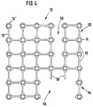
- FIG. 4 shows a grid according to FIG. 1, which has been cut to size by way of example in order to illustrate the different possible uses of a basic grid according to FIGS. 1 to 3.
- a gap 50 is cut into the grid 10 according to FIG. 4 by removing the webs 12.
- a free finger 54 can be created according to FIG. 4, bottom right, which projects like a cantilever from a plot of land with four holes for fastening screws.
- Free webs 58 which can hold smaller fragments or debris, protrude into a gap 56. 4, top left, shows a free-standing ring 14 'on a web 12'.
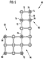
- FIG. 5 shows a grid 60 which has been prepared starting from a grid according to FIG. 1.
- the grid 60 is designed so that it has a bracket 62, to which the epithesis is later to be attached, and a base part 63, which is attached to the bone with screws 66, 68, 70, 72.
- a gap 64 is left where no attachment is required.
- Screws 74, 76, 78 serve to fasten an epithesis to the grid 60.
- FIG. 5 shows that the place of fastening the grid (base part 63) can be quite far from the place of fastening the epithesis (bracket 62). Starting from a grid according to one of FIGS. 1 to 3, there are many design options.
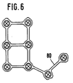
- FIG. 6 shows a configuration which is particularly advantageous in the event of broken fragments with very small fragments.
- Such small fragments can be fixed well with individual, individually bent finger extensions 80 according to FIG. 6.
- the finger extension (extension arm) 80 can be unwound by the surgeon as desired.
- Such individually bent finger extensions allow adaptation to the anatomy of the bone in all three levels.
- the lattice configurations described above are distinguished from the prior art on the one hand by the fact that they are convex and on the other hand by the fact that they are relatively small Cover the area with respect to the bone.
- convex means that the grid in its traded form is designed so that the connecting line of the centers of any two pairs of holes lies within the outer border of the grid, ie within the outer contour of the material parts of the grid.
- the connecting line of any two adjacent edge holes of the grating should coincide as far as possible with a web, whereby the three-dimensional stability of an optionally cut grating, which is screwed to a bone to be healed, is significantly promoted.
- the surface coverage of the grid with respect to the bone is not more than 45%, preferably not more than 35% and even more preferably not more than 30%.
- the term "surface coverage” describes in% the ratio of the total area between the outer contours of the grid including the perforations to the total area of the metal.
- the areas can be formed by parallel projection onto a plane that is parallel to the main plane of the grid, i.e. only two-dimensional extensions of the grid in its main plane are included in the calculation of the degree of coverage of the grid, but not profiles of the grid perpendicular to the main plane.
Landscapes
- Health & Medical Sciences (AREA)
- Orthopedic Medicine & Surgery (AREA)
- Life Sciences & Earth Sciences (AREA)
- General Health & Medical Sciences (AREA)
- Surgery (AREA)
- Biomedical Technology (AREA)
- Heart & Thoracic Surgery (AREA)
- Engineering & Computer Science (AREA)
- Veterinary Medicine (AREA)
- Animal Behavior & Ethology (AREA)
- Public Health (AREA)
- Oral & Maxillofacial Surgery (AREA)
- Transplantation (AREA)
- Cardiology (AREA)
- Neurology (AREA)
- Nuclear Medicine, Radiotherapy & Molecular Imaging (AREA)
- Vascular Medicine (AREA)
- Medical Informatics (AREA)
- Molecular Biology (AREA)
- Prostheses (AREA)
- Surgical Instruments (AREA)
Description
- Die Erfindung betrifft ein Gitter für die Osteosynthese oder zum Befestigen von künstlichen Körperteilen mit den Merkmalen des Oberbegriffs des Patentanspruchs 1.
- Unter der Osteosynthese versteht man die operative Verbindung der Endstellen eines Knochenbruchs durch mechanische Hilfsmittel.
- Bei Frakturen (Brüchen) und Osteotomien (operative Durchtrennung eines Knochens) insbesondere im Bereich des menschlichen Schädels ist eine sogenannte Fixation notwendig, d.h. eine feste Positionierung der Fragmente zueinander.
- Zum Fixieren der miteinander zu verbindenden Knochenstücke sind im Stand der Technik verschiedene Plattensysteme und auch Drahtnähte bekannt.
- Die Verwendung von Draht hat den Nachteil einer mangelhaften Funktionsstabilität. Drahtnähte kommen deshalb nur noch selten und bei kleinen Fragmenten zur Anwendung, wo jedoch die Einfädelung äußerst schwierig ist und oftmals zu einer völligen Denudierung des Knochens führt, d.h. einer unerwünschten Entfernung der Knochenhaut.
- Bekannte Plattensysteme für die Osteosynthese haben gegenüber der Drahtnaht zwar Verbesserungen gebracht, sind jedoch ebenfalls mit Nachteilen behaftet. So muß die Fraktur relativ umfangreich freigelegt und präpariert werden, was den Heilungsprozeß verzögert. Auch haben bekannte Plattensysteme den Nachteil, daß eine Stabilisierung der Knochenfragmente im wesentlichen nur zweidimensional erfolgt. Werden aber mehrere großflächige Platten verwendet, so werden auch die über den Platten zum Liegen kornenden Weichteile vom Knochen abgehalten, was den Heilungsprozeß ebenfalls behindern kann. Überdies haben die bekannten Plattensysteme auch den Nachteil, daß sie nur mit sehr viel Aufwand exakt an den Knochenbau angepaßt werden können. Gelingt diese Anpassung nicht exakt, so besteht die Gefahr eines Verziehens der Knochenteile.
- Aus dem DE-GM 87 06 912 sind sogenannte Kleinknochenplatten bekannt, bei denen zwischen einzelnen ringförmigen Lochfassungen Stege vorgesehen sind. Diese Kleinknochenplatten sind aber nicht netzförmig und sie decken im Verhältnis zu ihrer Gesamtgröße eine relativ große Knochenfläche ab. Entsprechendes gilt für die US-PS 2 494 229 und das DE-GM 85 28 003. Auch die EP 0 291 632 A1 beschreibt Kleinknochenplatten, bei der im Verhältnis zur Gesamtfläche der Knochenplatte ein relativ großer Anteil des Knochens abgedeckt wird.
- Das DE-U-88 07 909 beschreibt eine Knochenplatte für die Osteosynthese mit Gittern zum Verankern der Platte, bei denen langgestreckte Stege zwischen einzelnen Schraublochfassungen vorgesehen sind. Dabei greifen aber freistehende Stege wie Arme nach außen und zwischen außenliegenden Schraubenlöchern sind keine Stege vorgesehen.
- Bevor das vorstehend beschriebene Osteosynthesematerial mittels Schrauben od. dergl. am Knochen befestigt wird, ist die betroffene Knochenfläche freizulegen. In Folge dieser Denudierung des Knochens wird die Gefäßversorgung der betroffenen Knochenteile unterbrochen, was zu einem flächigen Abbau von Knochenmaterial im denudierten Bereich führen kann bis die Gefäßversorgung aufgrund des natürlichen Heilungsprozesses wieder hergestellt ist. Der Stand der Technik ist dahingehend verbesserungfähig, als dem Chirurgen die Möglichkeit gegeben werden sollte, die Knochenoberfläche nur so gering als möglich freizulegen. Und das Osteosynthesematerial sollte in montiertem Zustand nur eine relativ geringe Knochenfläche abdecken, damit während des Heilungsvorganges die Gefäßversorgung so schnell wie möglich und so flächendeckend wie möglich hergestellt werden kann. Ein Abbau von Knochen unter dem Osteosynthesematerial sollte soweit als möglich vermieden werden.
- Neben der anzustrebenden möglichst geringen Flächenabdeckung des Osteosynthesematerials in bezug auf die Gesamtfläche des Gitters ist aber auch eine hohe mechanische Stabilität des Gesamtsystems aus im Knochen verschraubtem Gitter und dem zu verheilenden Knochen erforderlich. Die Forderungen nach möglichst geringer Flächenabdeckung einerseits und hoher mechanischer Stabilität andererseits sind gegenläufig.
- Der vorliegenden Erfindung liegt die Aufgabe zugrunde, ein Gitter für die Osteosynthese sowie zum Befestigen von künstlichen Körperteilen, wie Epithesen, zu schaffen, welches einerseits einen günstigen Verlauf der Knochenheilung und andererseits eine hohe dreidimensionale Stabilität des Systems aus Gitter, Knochen und Schrauben ermöglicht.
- Erfindungsgemäß wird diese Aufgabe dadurch gelöst, daß die Verbindungslinie der Mittelpunkte jeweils zweier beliebiger Löcher des Gitters innerhalb der äußeren Umrandung des Gitters liegt und daß das Gitter nicht mehr als 45 % des von ihm belegten Knochens abdeckt.
- Bevorzugt ist das erfindungsgemäße Gitter so ausgestaltet, daß die Verbindungslinie von jeweils zwei beliebigen benachbarten Löchern, die am Rand des Gitters liegen, jeweils die Mittellinie eines Steges ist.
- Die Erfindung beruht auf der Erkenntnis, daß der Chirurg dann optimale Ergebnisse hinsichtlich der Stabilität des Systems und gleichzeitig hinsichtlich des Heilungsverlaufes erzielen kann, wenn einerseits zur Förderung der dreidimensionalen Stabilität des Gitters die Verbindungslinie von allen möglichen Loch-Paaren des Gitters jeweils innerhalb der äußeren Umrandung des Gitters liegt und andererseits die Knochenabdeckung möglichst gering ist.
- Das erfindungsgemäße Gitter kann vom Chirurgen vor Ort präpariert werden, um es an die Erfordernisses des Einzelfalles anzupassen. Dabei kann der Chirurg das Gitter so zurechtschneiden, daß zwischen zwei Randlöchern ein Steg stehen bleibt und so ein zweidimensionales Gitterstück verbleibt, von dem gegebenenfalls ausgreifende Arme abstehen. Wird dieses zweidimensionale, an seinen Rändern durch Stege stabilisierte Gebilde mit dem Knochen verschraubt, so entsteht insgesamt eine dreidimensionale stabile Struktur.
- Weitere bevorzugte Ausgestaltungen des Erfindungsgegenstandes sind in den Unteransprüchen beschrieben.
- Die Erfindung bezieht sich somit auf ein handelbares Produkt, welches so gestaltet ist, daß es durch einfache Manipulationen vor Ort vielfältig entsprechend den Anforderungen des Einzelfalles abwandelbar ist.
- Mit durch die Löcher in den Knochen eingedrehten Schrauben entsteht als Grundgerüst ein Quader (dreidimensional).
- Im Unterschied zum Stand der Technik, bei dem großflächige Platten mit einer Vielzahl von Löchern versehen sind, sieht also die Erfindung eine grazile Stegkonstruktion vor, wobei die Versteifung und die Stabilität durch schmale Stege erreicht wird. Eine solche gitterförmige Struktur läßt sich leicht an den individuellen Knochenbau anpassen und liefert trotzdem eine gute dreidimensionale Stabilität, insbesondere wenn Schrauben an den Ecken eines durch das Gitter gebildeten Vierecks durch die Löcher in den Knochen eingeschraubt werden.
- Gemäß einer bevorzugten Ausgestaltung der Erfindung weisen die feinen Stege zumindest teilweise jeweils eine Länge von mehr als 4 mm und eine Breite von weniger als 1,5 mm, vorzugsweise weniger als 1 mm auf.
- Gemäß einer anderen bevorzugten Weiterbildung der Erfindung ist vorgesehen, daß die Stege zumindest teilweise eine Länge von mehr als 5 mm aufweisen, wobei sie über diese gesamte Länge die vorstehend angegebenen Breiten aufweisen.
- Eine besonders umfangreiche Gestaltungsfreiheit wird dem Chirurgen dann in die Hand gegeben, wenn die erfindungsgemäßen Gitter mit unterschiedlichen Steg-Strukturen, d.h. Längen der Stege und ihren geometrischen Anordnungen, bereitgestellt werden, so daß vor Ort die Gitter wahlweise durch Entfernen bestimmter Partien dem gegebenen Problem optimal angepaßt werden können.
- Das erfindungsgemäße Gitter für die Osteosynthese hat gegenüber herkömmlichen Plattensystemen den Vorteil, daß die Stabilität der Fixation im wesentlichen durch die Form des Gitters bedingt ist, nicht aber durch die Stärke oder Länge der Platte. Das erfindungsgemäße Gitter kann so gestaltet werden, daß es einfach an die geforderte Geometrie der Osteosynthese anpaßbar ist. Es ist gut biegsam und wird erst nach der Verschraubung aufgrund der dreidimensionalen Versteifung stabil. Eine intermaxilläre Fixation ist nicht erforderlich.
- Weiter hat das erfindungsgemäße Gitter den Vorteil, daß eine übermäßige Denudierung (Freilegung) des Knochens vermieden werden kann. Bei der Anbringung des erfindungsgemäßen Gitters braucht nur relativ wenig Periost abgeschoben zu werden. Da das Periost (bindegewebige Hautschicht um den Knochen) durch Nährstoffzufuhr zum Knochen, die das ganze Leben fortdauernde Knochenerneuerung (endostale Ossifikation) gewährleistet, kann bei einer erfindungsgemäßen Osteosynthese der Heilungsprozeß rascher und störungsunanfälliger erfolgen.
- Da ein erfindungsgemäßes Gitter parallel zur Fraktur gelegt werden kann, muß in unmittelbarer Nähe des Fraktur- bzw. des Osteotomiespaltes das Periost abgeschoben werden. Auch dieser Umstand ermöglicht bei Verwendung eines erfindungsgemäßen Gitters eine bessere Blutversorgung der Fragmente und damit einen besseren Heilungsverlauf.
- Weiter ermöglicht ein erfindungsgemäßes Gitter eine individuelle Anpassung an extrem komplizierte geometrische Anforderungen aufgrund des Bruches. Wird das erfindungsgemäße Gitter beispielsweise in Stücken von 6 x 6 cm Kantenlänge bereitgestellt, so kann der Chirurg vor Ort aus einem solchen Gitterstück je nach der vorliegenden Osteotomie bzw. dem Frakturverlauf gewünschte Stücke herausschneiden. Besonders bei Trümmerbrüchen sind auf diese Weise Kleinstfragmente mit einzelnen, individuell angebogenen Fingerfortsätzen gut fixierbar. Die Fragmente brauchen nicht durch zusätzliche Drahtnähte fixiert zu werden und auch eine Denudierung kann weitgehend vermieden werden.
- Weiter haben erfindungsgemäße Gitter auch den Vorteil, daß bei ihrer Anbringung nicht große Areale von Gewebe freigelegt werden müssen. Deshalb ist auch die spätere Entfernung eines erfindungsgemäßen Gitters von der Bruchstelle relativ einfach und kann sogar in Lokalanästhesie durchgeführt verden. Auch beim Entfernen des Gitters muß nur das ehemalige Operationsgebiet geringfügig freigelegt werden.
- Darüberhinaus hat das erfindungsgemäße grazile Gitter den Vorteil, nicht aufzutragen. Dies ist sowohl medizinisch als auch ästhetisch von Vorteil.
- Eine Variante der Erfindung betrifft statt der Osteosynthese die Befestigung von Epithesen, insbesondere im Bereich des menschlichen Gesichtes. Das in den Ansprüchen beschriebene erfindungsgemäße Gitter ist auch für diesen Zweck geeignet.
- Zur Befestigung von Epithesen (künstlichen Ohren, Nasen, Augen etc.) im Bereich des Gesichtes werden gemaß dem Stand der Technik in der Regel Hilfsmittel wie eine Brille oder eine Prothese verwendet.
- Eine andere Lösung zum Befestigen von Epithesen im Bereich des Gesichtes sieht vor, daß einzelne Implantate im Schädelknochen fixiert werden, an denen dann die Epithese befestigt wird, wie bei Implantaten in der Mundhöhle zur Fixation von Zahnprothesen. Der Nachteil eines solchen Implantatsystems liegt vor allem darin, daß genügend Knochen vorhanden sein muß, um die Implantatpfosten aufnehmen zu können. So ist es häufig nicht möglich, am Ort der zu befestigenden Epithese die Implantatpfosten zu setzen. Auch haben solche Implantatpfosten den Nachteil, daß sie ein sogenanntes "zweistufiges" Verfahren erfordern, wobei zunächst der Implantatpfosten in den Knochen eingefügt wird und dort eine längere Zeit ohne Belastung durch die Epithese verbleibt, um einheilen zu können. Erst danach wird mit zeitlichem Abstand von einigen Monaten dann auf dem oder den Implantatpfosten die Epithese bei einer zweiten Operation befestigt.
- Auch haben bekannte Vorrichtungen zum Befestigen von Epithesen den Nachteil, daß die Stellung und die Form der Epithese nicht immer optimal sein kann, da man beim Setzen der Implantate ungünstigen Randbedingungen unterliegt, d.h. die Implantate nicht dort setzen kann, wo sie für einen idealen Sitz der Epithese wünschenswert wären.
- Ein solches erfindungsgemäßes Gitter zum Befestigen von Epithesen weist alle oben in Zusammenhang mit der Osteosynthese genannten Vorteile auf.
- Darüberhinaus hat das erfindungsgemäße Gitter beim Befestigen von Epithesen den Vorteil, daß mit zwei bis drei kurzen Schrauben das Gitter am festen Knochen verankert werden kann. Durch die Verwendung von kurzen Schrauben sind keine dicken Knochenstrukturen zum Befestigen der Epithese notwendig und es werden auch Störungen der Infrastruktur des Knochens weitgehend vermieden. Dies ist insbesondere im Bereich des Gehirnschädels und bei Kindern wichtig.
- Das erfindungsgemäße Gitter wird mit relativ kurzen 2- bis 4-mm-Schrauben am Knochen befestigt, wobei eine sehr gute Stabilität gegeben ist, da die dünnen Gitter-Stege zwischen den Schrauben sehr schnell vom Knochen überwachsen werden.
- Ein weiterer wesentlicher Vorteil des erfindungsgemäßen Gitters liegt darin, daß es an einem anderen Ort am Knochen befestigbar ist als der für die Epithese vorgesehene Ort. Ein erfindungsgemäßes Gitter kann wie ein "Kran" derart eingesetzt werden, daß es mit bestimmten Teilen an einem günstigen Knochenstück befestigt wird, während z.B. einige Zentimeter davon entfernt dann an einem Ausleger des Gitters die Epithese befestigt werden kann. Auf der Basis dieses "Kran"- bzw."Auslegerprinzips" ist es also möglich, eine Epithese an einem Ort zu positionieren und mit Hilfe des erfindungsgemäßen Gitters zu befestigen, an dem unterhalb der Epithese gar kein Knochen zur Verfügung steht.
- Auch ermöglicht es das erfindungsgemäße Gitter, die Epithesenstellung individuell anzupassen.
- Weiterhin kann mit einem erfindungsgemäßen Gitter die Epithese in einem einzigen Arbeitsgang installiert werden, da die Befestigung des Gitters am Knochen an ganz anderer Stelle stattfinden kann als am Ort der zu fixierenden Epithese, d.h. die Durchtrittsstelle durch die Haut ist nicht durch den Ort der Befestigung der Epithese festgelegt, sondern kann an eine günstigere Stelle verlegt werden.
- Alle diese Möglichkeiten standen bei herkömmlichen Schraubenimplantaten nicht zur Verfügung.
- Nachfolgend wird die Erfindung anhand der Zeichnung näher erläutert. Es zeigt:
- Fig. 1
- eine Draufsicht auf ein Gitter;
- Fig. 2
- eine Draufsicht auf ein anderes Ausführungsbeispiels eines Gitters;
- Fig. 3
- ein weiteres Ausführungsbeispiel eines Gitters mit abgewandelten Stegformen; und
- Fig. 4, 5 und 6
- Gitter gemäß Fig. 1, die vom Benutzer zurechtgeschnitten sind.
- Das in Fig. 1 gezeigte Gitter 10 ist gegenüber seinem realen Maßstab zweifach vergrößert, d.h. die reale Kantenlänge beträgt etwa 5 cm x 5 cm.
- Das Gitter 10 weist eine Vielzahl von jeweils einzelne Quadrate bildenden Stegen 12 auf. Das Gitter besteht insgesamt einstückig aus Titan.
- Die einzelnen Stege 12 sind jeweils matrixförmig über Ringe 14 miteinander verbunden. Die Ringe 14 sind gerade so groß, daß sie Löcher 20 aufnehmen können, durch welche z.B. Schrauben durchsteckbar sind. Die Löcher 20 können auch mit Innengewinde versehen sein, um die Befestigung von Epithesen oder dergleichen zu ermöglichen.
- Zwischen den Stegen 12 sind rechteckförmige Freiräume 16 freigelassen.
- Die Löcher 20 sind jeweils mit Ansenkungen 18 versehen, so daß Schrauben koplanar mit der Oberfläche des Gitters versenkt werden können.
- Der Abstand L₁ zweier benachbarter Steg-Kreuzungspunkte beträgt beim in Fig. 1 dargestellten Ausführungsbeispiel 1 cm. Abweichungen hiervon von ± 2 mm ermöglichen ebenfalls günstige Stegstrukturen. Die Stege 12 sind über ihre gesamte freie Länge L₂ relativ schmal, beim dargestellten Ausführungsbeispiel beträgt ihre Breite B nicht mehr als 1 mm.
- Die Höhe (in der Zeichnungsebene) des gesamten Gitters ist gleichmäßig und beim dargestellten Ausführungsbeispiel nicht größer als 1 mm.
- Fig. 2 zeigt eine Abwandlung des in Fig. 1 dargestellten Gitters, wobei die Länge der Stege unterschiedlich ist, was dem Chirurgen erweiterte Gestaltungsfreiheit beim Einsatz des Gitters ermöglicht. Das in den Fig. 1 und 2 dargestellte Gitter kann vor Ort mit einfachen Werkzeugen gemäß den Anforderungen zurechtgeschnitten und -gebogen werden (siehe oben).
- Die unterschiedlichen Längen L₃ und L₄ gemäß Fig. 2 ermöglichen einerseits eine Konzentration von Schrauben bei beengten Verhältnissen und andererseits die Überbrückung längerer Strecken mit wenig Material.
- Fig. 3 zeigt Abwandlungen der Steg- und Ringstruktur. Das Gitter 10 weist sehr unterschiedliche Anordnungen von Ringen und Stegen auf, wobei die Stege 22, 24 nicht zwischen Ringen 14 verlaufen, sondern eine zusätzliche Stabilisierung des Gitters in sich bewirken sollen. Der Aufbau des in Fig. 3 gezeigten Gitters versteht sich von selbst ohne Beschreibung. Die dargestellte Struktur ist Teil der Erfindung.
- Fig. 4 zeigt ein Gitter gemäß Fig. 1, das beispielhaft zurechtgeschnitten ist, um die unterschiedlichen Einsatzmöglichkeiten eines Grundgitters gemäß den Fig. 1 bis 3 zu veranschaulichen.
- In das Gitter 10 gemäß Fig. 4 ist zum Beispiel eine Lücke 50 durch Entfernen der Stege 12 geschnitten. Hierdurch entsteht ein freier Arm 52, der vom Chirurgen leicht an die Erfordernisse geometrisch anpaßbar ist. Durch Wegnahme von Stegen 12 und Ringen 14 kann gemäß Fig. 4, rechts unten, ein freier Finger 54 geschaffen werden, der wie ein Ausleger von einem vier Löcher zum Befestigen von Schrauben aufweisenden Grundstück absteht. In eine Lücke 56 ragen freie Stege 58, die kleinere Fragmente oder Trümmer halten können. Weiterhin zeigt Fig. 4, links oben, einen freistehenden Ring 14' an einem Steg 12'.
- Durch die Wegnahme von Stegen und die Bildung der in Fig. 4 gezeigten Lücken ist es möglich, die Denudierung des Knochens auf das unumgängliche Maß zu beschränken.
- Fig. 5 zeigt ein Gitter 60, das ausgehend von einem Gitter gemäß Fig. 1 präpariert worden ist. Das Gitter 60 ist so gestaltet, daß es zum einen einen Ausleger 62 aufweist, an dem später die Epithese befestigt werden soll, sowie ein Grundteil 63, das mit Schrauben 66, 68, 70, 72 am Knochen befestigt ist. Dort wo keine Befestigung erforderlich ist, ist eine Lücke 64 gelassen.
- Schrauben 74, 76, 78 dienen zur Befestigung einer Epithese am Gitter 60. Fig. 5 zeigt, daß der Ort der Befestigung des Gitters (Grundteil 63) recht weit vom Ort der Befestigung der Epithese (Ausleger 62) entfernt sein kann. Ausgehend von einem Gitter gemäß einer der Fig. 1 bis 3 sind vielfältige Gestaltungsmöglichkeiten gegeben.
- Fig. 6 zeigt eine Konfiguration, die besonders bei Trümmerbrüchen mit Kleinstfragnenten vorteilhaft ist. Mit einzelnen, individuell angebogenen Fingerfortsätzen 80 gemäß Fig. 6 können solche Kleinstfragmente gut fixiert werden. Der Fingerfortsatz (Verlängerungsarm) 80 kann vom Chirurgen wunschgemäß abgewickelt werden. Solche individuell angebogenen Fingerfortsätze ermöglichen in allen drei Ebenen eine Anpassung an die Anatomie des Knochens.
- Die vorstehend beschriebenen Gitterkonfigurationen zeichnen sich gegenüber dem Stand der Technik zum einen dadurch aus, daß sie konvex sind und zum anderen dadurch, daS sie eine relativ geringe Flächenabdeckung bezüglich des Knochens bewirken. Der Begriff "konvex" bedeutet, daß das Gitter in seiner gehandelten Form so gestaltet ist, daß die Verbindungslinie der Mittelpunkte zweiter beliebiger Loch-Paare innerhalb der äußeren Umrandung des Gitters liegt, d.h. innerhalb der äußeren Kontur der materiellen Teile des Gitters. Dabei soll die Verbindungslinie von jeweils zwei beliebigen benachbarten Rand-Löchern des Gitters möglichst mit einem Steg zusammenfallen, wodurch die dreidimensionale Stabilität eines gegebenfalls zurechtgeschnittenen Gitters, das mit einem zu verheilenden Knochen verschraubt ist, erheblich gefördert wird. Gleichzeitig beträgt die Flächenabdeckung des Gitters bezüglich des Knochens nicht mehr als 45 %, bevorzugt nicht mehr als 35 % und noch weiter bevorzugt nicht mehr als 30 %. Der Begriff "Flächenabdeckung" beschreibt in % das Verhältnis der Gesamtfläche zwischen den äußeren Konturen des Gitters einschließlich der Perforationen zur Gesamtfläche des Metalles. Dabei können die Flächen durch Parallel-Projektion auf eine Ebene oebildet werden, die parallel zur Hauptebene des Gitters liegt, d.h. in die Berechnung des Abdeckungsgrades des Gitters gehen nur zweidimendionale Erstreckungen des Gitters in seiner Hauptebene ein, nicht aber Profilierungen des Gitters senkrecht zur Hauptebene.
Claims (8)
- Gitter für die Osteosynthese oder zum Befestigen von künstlichen Körperteilen, wie Epithesen, mit einer Mehrzahl von netzartig angeordneten Stegen (12), wobei an zumindest einem Teil der Kreuzungspunkte der Stege Löcher (20) für Befestigungsschrauben vorgesehen sind,
dadurch gekennzeichnet, daß
die gerade Verbindungslinie von jeweils zwei beliebigen benachbarten Löchern (20), die am Rand des Gitters (10) liegen, jeweils die Mittellinie eines Steges (12) ist und innerhalb der äußeren Umrandung des Gitters liegt, und daß das Gitter einen Knochen-Abdeckungsgrad von nicht mehr als 45% aufweist. - Gitter nach Anspruch 1,
dadurch gekennzeichnet, daß
zumindest ein Teil der Stege (12) jeweils eine Länge (L₂) von mehr als 4 mm und eine Breite (B) von weniger als 1,5 mm aufweist. - Gitter nach Anspruch 1,
dadurch gekennzeichnet, daß
zumindest ein Teil der Stege (12) jeweils eine Länge (L₂) von mehr als 4 mm und eine Breite (B) von weniger als 1,5 mm aufweist. - Gitter nach einem der vorhergehenden Ansprüche,
dadurch gekennzeichnet, daß
die Stege (12) eine Höhe kleiner als 1,2 mm, vorzugsweise kleiner als 1 mm aufweisen. - Gitter nach einem der vorhergehenden Ansprüche,
dadurch gekennzeichnet, daß
zumindest ein Teil der Löcher (20) ein Innengewinde aufweist. - Gitter nach einem der vorhergehenden Ansprüche,
dadurch gekennzeichnet, daß
das Gitter im Bereich zumindest eines Teils der Kreuzungspunkte der Stege (12) Ringe (14) zur Aufnahme der Löcher (20) aufweist. - Gitter nach einm der vorhergehenden Ansprüche,
dadurch gekennzeichnet, daß
seine äußere Umrandung quadratisch, rechteckförmig, kreisförmig, dreieckförmig, ellipsenförmig oder rautenförmig ist. - Gitter nach einem der vorhergehenden Ansprüche,
dadurch gekennzeichnet, daß
es nicht mehr als 35%, vorzugsweise nicht mehr als 30% des von ihm belegten Knochens abdeckt.
Priority Applications (1)
| Application Number | Priority Date | Filing Date | Title |
|---|---|---|---|
| DE9018077U DE9018077U1 (de) | 1989-12-22 | 1990-12-11 | Gitter für die Osteosynthese und zum Befestigen von künstlichen Körperteilen |
Applications Claiming Priority (2)
| Application Number | Priority Date | Filing Date | Title |
|---|---|---|---|
| DE3942676 | 1989-12-22 | ||
| DE3942676 | 1989-12-22 |
Publications (2)
| Publication Number | Publication Date |
|---|---|
| EP0433852A1 EP0433852A1 (de) | 1991-06-26 |
| EP0433852B1 true EP0433852B1 (de) | 1996-03-13 |
Family
ID=6396257
Family Applications (1)
| Application Number | Title | Priority Date | Filing Date |
|---|---|---|---|
| EP90123827A Revoked EP0433852B1 (de) | 1989-12-22 | 1990-12-11 | Gitter für die Osteosynthese oder zum Befestigen von künstlichen Körperteilen |
Country Status (3)
| Country | Link |
|---|---|
| EP (1) | EP0433852B1 (de) |
| AT (1) | ATE135183T1 (de) |
| DE (3) | DE4028021C1 (de) |
Cited By (15)
| Publication number | Priority date | Publication date | Assignee | Title |
|---|---|---|---|---|
| US6618623B1 (en) | 2000-11-28 | 2003-09-09 | Neuropace, Inc. | Ferrule for cranial implant |
| US7158833B2 (en) | 2000-11-28 | 2007-01-02 | Neuropace, Inc. | Ferrule for cranial implant |
| US8073544B2 (en) | 2000-04-05 | 2011-12-06 | Neuropace, Inc. | Neurostimulator involving stimulation strategies and process for using it |
| US8224452B2 (en) | 2000-04-05 | 2012-07-17 | Neuropace Inc. | Differential neurostimulation therapy driven by physiological therapy |
| US8298292B2 (en) | 2003-04-16 | 2012-10-30 | Howmedica Osteonics Corp. | Craniofacial implant |
| US8398720B2 (en) | 2003-04-16 | 2013-03-19 | Orthovita, Inc. | Craniofacial implant |
| US8795377B2 (en) | 2010-03-10 | 2014-08-05 | Ossdsign Ab | Implants and methods for correcting tissue defects |
| US9220597B2 (en) | 2013-02-12 | 2015-12-29 | Ossdsign Ab | Mosaic implants, kits and methods for correcting bone defects |
| US9463046B2 (en) | 2011-08-22 | 2016-10-11 | Ossdsign Ab | Implants and methods for using such implants to fill holes in bone tissue |
| US10076416B2 (en) | 2013-02-12 | 2018-09-18 | Ossdsign Ab | Mosaic implants, kits and methods for correcting bone defects |
| US10881519B2 (en) | 2014-08-14 | 2021-01-05 | Ossdsign Ab | Bone implants for correcting bone defects |
| US10898332B2 (en) | 2015-11-24 | 2021-01-26 | Ossdsign Ab | Bone implants and methods for correcting bone defects |
| USD909580S1 (en) | 2019-04-05 | 2021-02-02 | Sunnybrook Research Institute | Surgical mesh implant |
| US12508054B2 (en) | 2018-10-16 | 2025-12-30 | Ossdsign Ab | Implants for filling bore holes in bone and methods for filling bore holes in bone |
| US12629252B2 (en) | 2018-04-06 | 2026-05-19 | Sunnybrook Research Institute | Formable mesh for correcting bone defects |
Families Citing this family (18)
| Publication number | Priority date | Publication date | Assignee | Title |
|---|---|---|---|---|
| DE4111856C1 (de) * | 1991-04-11 | 1992-07-16 | Oswald Leibinger Gmbh, 7202 Muehlheim, De | |
| US5346492A (en) * | 1992-03-30 | 1994-09-13 | Timesh, Inc. | Perforated metallic panels and strips for internal fixation of bone fractures and for reconstructive surgery |
| US5468242A (en) * | 1993-11-19 | 1995-11-21 | Leibinger Gmbh | Form-fitting mesh implant |
| DE19603887C2 (de) | 1996-02-03 | 1998-07-02 | Lerch Karl Dieter | Anordnung zum Fixieren eines aus der Schädelkapsel zum Zwecke des operativen Eingriffs herausgetrennten Knochenstücks am verbliebenen Schädelbein |
| WO1997029708A1 (en) | 1996-02-14 | 1997-08-21 | Walter Lorenz Surgical, Inc. | Bone fastener and instrument for insertion thereof |
| US5718705A (en) * | 1996-07-16 | 1998-02-17 | Sammarco; Giacomo J. | Internal fixation plate |
| US5690631A (en) * | 1996-09-11 | 1997-11-25 | Walter Lorenz Surgical, Inc. | Multi-configurable plating system |
| US5766176A (en) * | 1996-09-11 | 1998-06-16 | Walter Lorenz Surgical, Inc. | Formable mesh |
| US5752958A (en) * | 1997-04-02 | 1998-05-19 | Wellisz; Tadeusz Z. | Bone fixation plate |
| US5980540A (en) * | 1997-04-11 | 1999-11-09 | Kinamed, Inc. | Perforated cover for covering spaces in the cranium and conforming to the shape of the cranium |
| US5916200A (en) * | 1997-10-01 | 1999-06-29 | Walter Lorenz Surgical, Inc. | Apparatus and method for stabilization of a cranial shunt |
| US6093188A (en) * | 1997-11-10 | 2000-07-25 | Murray; William M. | Adjustable bone fixation plate |
| DE29909025U1 (de) * | 1999-05-25 | 1999-11-04 | Lipat Consulting Ag, Basel | Osteosynthetische Knochenplatte |
| US6379363B1 (en) | 1999-09-24 | 2002-04-30 | Walter Lorenz Surgical, Inc. | Method and apparatus for reattachment of a cranial flap using a cranial clamp |
| WO2002013716A1 (de) | 2000-08-16 | 2002-02-21 | Medartis Ag | Zahnschiene |
| FR2829685B1 (fr) | 2001-09-14 | 2004-07-23 | Obl | Implant-plaque |
| US6685707B2 (en) | 2001-09-25 | 2004-02-03 | Walter Lorenz Surgical, Inc. | Cranial clamp and method for fixating a bone plate |
| EP1708629A4 (de) * | 2004-01-08 | 2011-08-17 | David Mark Allison | Knochenfixiervorrichtung |
Family Cites Families (7)
| Publication number | Priority date | Publication date | Assignee | Title |
|---|---|---|---|---|
| FR742618A (de) * | 1933-03-10 | |||
| US2494229A (en) * | 1946-07-08 | 1950-01-10 | John G Collison | Bone surgery |
| US3710789A (en) * | 1970-12-04 | 1973-01-16 | Univ Minnesota | Method of repairing bone fractures with expanded metal |
| DE8528003U1 (de) * | 1985-10-02 | 1986-01-09 | Oswald Leibinger GmbH, 7202 Mühlheim | Knochenplatte |
| DE8706912U1 (de) * | 1987-05-14 | 1987-08-27 | Howmedica GmbH, 2314 Schönkirchen | Kleinknochenplatte und Schrauben, insbesondere für die Versorgung von Frakturen des Schädel- und Gesichtsskeletts o. dgl. |
| US4905679A (en) * | 1988-02-22 | 1990-03-06 | M P Operation, Inc. | Bone fracture reduction device and method of internal fixation of bone fractures |
| DE8807909U1 (de) * | 1988-06-18 | 1988-10-20 | Howmedica GmbH, 2314 Schönkirchen | Knochenplatte, insbesondere Kleinknochenplatte |
-
1990
- 1990-09-04 DE DE4028021A patent/DE4028021C1/de not_active Expired - Lifetime
- 1990-12-11 AT AT90123827T patent/ATE135183T1/de active
- 1990-12-11 EP EP90123827A patent/EP0433852B1/de not_active Revoked
- 1990-12-11 DE DE59010194T patent/DE59010194D1/de not_active Revoked
- 1990-12-11 DE DE9018077U patent/DE9018077U1/de not_active Expired - Lifetime
Cited By (20)
| Publication number | Priority date | Publication date | Assignee | Title |
|---|---|---|---|---|
| US8073544B2 (en) | 2000-04-05 | 2011-12-06 | Neuropace, Inc. | Neurostimulator involving stimulation strategies and process for using it |
| US8224452B2 (en) | 2000-04-05 | 2012-07-17 | Neuropace Inc. | Differential neurostimulation therapy driven by physiological therapy |
| US8326417B2 (en) | 2000-04-05 | 2012-12-04 | Neuropace, Inc. | Neurostimulator involving stimulation strategies and process for using it |
| US8412333B2 (en) | 2000-04-05 | 2013-04-02 | Neuropace, Inc. | Neurostimulator involving stimulation strategies and process for using it |
| US8694106B2 (en) | 2000-04-05 | 2014-04-08 | Neuropace, Inc. | Neurostimulator involving stimulation strategies and process for using it |
| US7158833B2 (en) | 2000-11-28 | 2007-01-02 | Neuropace, Inc. | Ferrule for cranial implant |
| US6618623B1 (en) | 2000-11-28 | 2003-09-09 | Neuropace, Inc. | Ferrule for cranial implant |
| US8298292B2 (en) | 2003-04-16 | 2012-10-30 | Howmedica Osteonics Corp. | Craniofacial implant |
| US8398720B2 (en) | 2003-04-16 | 2013-03-19 | Orthovita, Inc. | Craniofacial implant |
| US8795377B2 (en) | 2010-03-10 | 2014-08-05 | Ossdsign Ab | Implants and methods for correcting tissue defects |
| US9445900B2 (en) | 2010-03-10 | 2016-09-20 | Ossdsign Ab | Implants and methods for correcting tissue defects |
| US9463046B2 (en) | 2011-08-22 | 2016-10-11 | Ossdsign Ab | Implants and methods for using such implants to fill holes in bone tissue |
| US9220597B2 (en) | 2013-02-12 | 2015-12-29 | Ossdsign Ab | Mosaic implants, kits and methods for correcting bone defects |
| US10076416B2 (en) | 2013-02-12 | 2018-09-18 | Ossdsign Ab | Mosaic implants, kits and methods for correcting bone defects |
| US10881519B2 (en) | 2014-08-14 | 2021-01-05 | Ossdsign Ab | Bone implants for correcting bone defects |
| US10898332B2 (en) | 2015-11-24 | 2021-01-26 | Ossdsign Ab | Bone implants and methods for correcting bone defects |
| US11865005B2 (en) | 2015-11-24 | 2024-01-09 | Ossdsign Ab | Bone implants and methods for correcting bone defects |
| US12629252B2 (en) | 2018-04-06 | 2026-05-19 | Sunnybrook Research Institute | Formable mesh for correcting bone defects |
| US12508054B2 (en) | 2018-10-16 | 2025-12-30 | Ossdsign Ab | Implants for filling bore holes in bone and methods for filling bore holes in bone |
| USD909580S1 (en) | 2019-04-05 | 2021-02-02 | Sunnybrook Research Institute | Surgical mesh implant |
Also Published As
| Publication number | Publication date |
|---|---|
| DE9018077U1 (de) | 1994-09-15 |
| DE4028021C1 (en) | 1991-05-29 |
| EP0433852A1 (de) | 1991-06-26 |
| ATE135183T1 (de) | 1996-03-15 |
| DE59010194D1 (de) | 1996-04-18 |
Similar Documents
| Publication | Publication Date | Title |
|---|---|---|
| DE4028021C1 (en) | Grid for osteosynthesis - has cross bars with bores at nodes to receive fixing screws | |
| EP1211993B1 (de) | Fixationssystem für knochen | |
| DE69029245T2 (de) | Fixierung eines Knochenbruchs und Fixierungsvorrichtungen mit Identitätskennzeichnungen | |
| DE69620930T2 (de) | Platte und Stift | |
| EP0347874B1 (de) | Vorrichtung zum Verbinden eines, insbesondere im Bereich des Oberschenkelhalses, gebrochenen Knochens | |
| DE69608968T2 (de) | Teleskopische knochenplatte zur knochenverlängerung durch streck-osteogenesis | |
| EP3294168B1 (de) | Orthognatisches säge- und positionierungsimplantat | |
| DE69207733T2 (de) | Wiederherstellungsimplantat für Augenhöhlen | |
| EP2062548B1 (de) | Medizinische Membranen zur Knochenregeneration | |
| DE69422268T2 (de) | Formschlüssiges Gitter-Implantat | |
| WO2005048857A1 (de) | Osteosyntheseplatten-set | |
| EP0510390A1 (de) | Platte zum Abdecken eines Bohrloches in einem Schädeldach im Zusammenhang mit dem Fixieren eines Schädel-Knochendeckels | |
| EP1464295A2 (de) | Implantat | |
| EP2648647A1 (de) | Verbesserte distraktionsmembran | |
| DE4004941A1 (de) | System fuer die durchfuehrung chirurgischer eingriffe, beispielsweise bei der behandlung von bruechen der wirbelsaeule, oder von degenerativen oder geschwulstschaedigungen | |
| EP1202675A1 (de) | Chirurgischer führungskörper | |
| WO2015155296A1 (de) | Praeformiertes implantat zur reposition und fixation einer zentrolateralen mittelgesichtsfraktur | |
| DE3803435C1 (en) | Implanted splint for rib fractures | |
| DE29820487U1 (de) | Laterales Kieferimplantat | |
| DE9014613U1 (de) | Gitter für die Osteosynthese und zum Befestigen von künstlichen Körperteilen | |
| EP3651685B1 (de) | Knochenaugmentationsstück und bausatz aus knochenaugmentationsstück mit eingesetztem (zahn-) implantat | |
| DE69618591T2 (de) | Mehrrichtungs-mandibulare Streckvorrichtung | |
| DE10335281A1 (de) | Gitteranordnung für die Osteosynthese | |
| EP3530224A1 (de) | Handgelenksarthrodeseplatte | |
| DE9309720U1 (de) | Subperiostales Implantat |
Legal Events
| Date | Code | Title | Description |
|---|---|---|---|
| PUAI | Public reference made under article 153(3) epc to a published international application that has entered the european phase |
Free format text: ORIGINAL CODE: 0009012 |
|
| AK | Designated contracting states |
Kind code of ref document: A1 Designated state(s): AT BE CH DE FR GB IT LI SE |
|
| 17P | Request for examination filed |
Effective date: 19910723 |
|
| 17Q | First examination report despatched |
Effective date: 19930719 |
|
| RAP1 | Party data changed (applicant data changed or rights of an application transferred) |
Owner name: LEIBINGER GMBH |
|
| GRAA | (expected) grant |
Free format text: ORIGINAL CODE: 0009210 |
|
| ITF | It: translation for a ep patent filed | ||
| AK | Designated contracting states |
Kind code of ref document: B1 Designated state(s): AT BE CH DE FR GB IT LI SE |
|
| PG25 | Lapsed in a contracting state [announced via postgrant information from national office to epo] |
Ref country code: LI Free format text: LAPSE BECAUSE OF NON-PAYMENT OF DUE FEES Effective date: 19960313 Ref country code: CH Free format text: LAPSE BECAUSE OF NON-PAYMENT OF DUE FEES Effective date: 19960313 |
|
| REF | Corresponds to: |
Ref document number: 135183 Country of ref document: AT Date of ref document: 19960315 Kind code of ref document: T |
|
| GBT | Gb: translation of ep patent filed (gb section 77(6)(a)/1977) |
Effective date: 19960313 |
|
| REF | Corresponds to: |
Ref document number: 59010194 Country of ref document: DE Date of ref document: 19960418 |
|
| ET | Fr: translation filed | ||
| PLBQ | Unpublished change to opponent data |
Free format text: ORIGINAL CODE: EPIDOS OPPO |
|
| PLBI | Opposition filed |
Free format text: ORIGINAL CODE: 0009260 |
|
| 26 | Opposition filed |
Opponent name: SYNTHES AG CHUR Effective date: 19910909 |
|
| PLBQ | Unpublished change to opponent data |
Free format text: ORIGINAL CODE: EPIDOS OPPO |
|
| PLBI | Opposition filed |
Free format text: ORIGINAL CODE: 0009260 |
|
| PLBF | Reply of patent proprietor to notice(s) of opposition |
Free format text: ORIGINAL CODE: EPIDOS OBSO |
|
| PLAB | Opposition data, opponent's data or that of the opponent's representative modified |
Free format text: ORIGINAL CODE: 0009299OPPO |
|
| 26 | Opposition filed |
Opponent name: MEDICON EG Effective date: 19961212 Opponent name: SOFAMOR DANEK Effective date: 19961210 Opponent name: GEBR. MARTIN GMBH & CO. KG Effective date: 19961206 Opponent name: SYNTHES AG CHUR Effective date: 19910909 |
|
| R26 | Opposition filed (corrected) |
Opponent name: SYNTHES AG CHUR * 961206 GEBR. MARTIN GMBH & CO. K Effective date: 19960909 |
|
| PLBF | Reply of patent proprietor to notice(s) of opposition |
Free format text: ORIGINAL CODE: EPIDOS OBSO |
|
| PLBF | Reply of patent proprietor to notice(s) of opposition |
Free format text: ORIGINAL CODE: EPIDOS OBSO |
|
| PLBF | Reply of patent proprietor to notice(s) of opposition |
Free format text: ORIGINAL CODE: EPIDOS OBSO |
|
| PGFP | Annual fee paid to national office [announced via postgrant information from national office to epo] |
Ref country code: SE Payment date: 19981027 Year of fee payment: 9 Ref country code: CH Payment date: 19981027 Year of fee payment: 9 |
|
| PGFP | Annual fee paid to national office [announced via postgrant information from national office to epo] |
Ref country code: AT Payment date: 19981028 Year of fee payment: 9 |
|
| PGFP | Annual fee paid to national office [announced via postgrant information from national office to epo] |
Ref country code: BE Payment date: 19981222 Year of fee payment: 9 |
|
| PLBQ | Unpublished change to opponent data |
Free format text: ORIGINAL CODE: EPIDOS OPPO |
|
| PLAB | Opposition data, opponent's data or that of the opponent's representative modified |
Free format text: ORIGINAL CODE: 0009299OPPO |
|
| R26 | Opposition filed (corrected) |
Opponent name: SOFAMOR DANEK * 19961212 MEDICON EG Effective date: 19961210 |
|
| PLAB | Opposition data, opponent's data or that of the opponent's representative modified |
Free format text: ORIGINAL CODE: 0009299OPPO |
|
| PG25 | Lapsed in a contracting state [announced via postgrant information from national office to epo] |
Ref country code: AT Free format text: LAPSE BECAUSE OF NON-PAYMENT OF DUE FEES Effective date: 19991211 |
|
| PG25 | Lapsed in a contracting state [announced via postgrant information from national office to epo] |
Ref country code: SE Free format text: LAPSE BECAUSE OF NON-PAYMENT OF DUE FEES Effective date: 19991212 |
|
| PG25 | Lapsed in a contracting state [announced via postgrant information from national office to epo] |
Ref country code: BE Free format text: LAPSE BECAUSE OF NON-PAYMENT OF DUE FEES Effective date: 19991231 |
|
| R26 | Opposition filed (corrected) |
Opponent name: SOFAMOR DANEK GROUP, INC. * 19961212 MEDICON EG Effective date: 19961210 |
|
| BERE | Be: lapsed |
Owner name: LEIBINGER G.M.B.H. Effective date: 19991231 |
|
| EUG | Se: european patent has lapsed |
Ref document number: 90123827.9 |
|
| PGFP | Annual fee paid to national office [announced via postgrant information from national office to epo] |
Ref country code: GB Payment date: 20001107 Year of fee payment: 11 |
|
| PGFP | Annual fee paid to national office [announced via postgrant information from national office to epo] |
Ref country code: FR Payment date: 20001204 Year of fee payment: 11 |
|
| PGFP | Annual fee paid to national office [announced via postgrant information from national office to epo] |
Ref country code: DE Payment date: 20001222 Year of fee payment: 11 |
|
| RDAH | Patent revoked |
Free format text: ORIGINAL CODE: EPIDOS REVO |
|
| RDAG | Patent revoked |
Free format text: ORIGINAL CODE: 0009271 |
|
| STAA | Information on the status of an ep patent application or granted ep patent |
Free format text: STATUS: PATENT REVOKED |
|
| 27W | Patent revoked |
Effective date: 20010218 |
|
| GBPR | Gb: patent revoked under art. 102 of the ep convention designating the uk as contracting state |
Free format text: 20010218 |