EP0432103A2 - Thermostatventil zur Regelung des Durchflusses des Kühlmittels für Brennkraftmaschinen - Google Patents
Thermostatventil zur Regelung des Durchflusses des Kühlmittels für Brennkraftmaschinen Download PDFInfo
- Publication number
- EP0432103A2 EP0432103A2 EP90830460A EP90830460A EP0432103A2 EP 0432103 A2 EP0432103 A2 EP 0432103A2 EP 90830460 A EP90830460 A EP 90830460A EP 90830460 A EP90830460 A EP 90830460A EP 0432103 A2 EP0432103 A2 EP 0432103A2
- Authority
- EP
- European Patent Office
- Prior art keywords
- support
- flange part
- casing
- valve
- thermostatic valve
- Prior art date
- Legal status (The legal status is an assumption and is not a legal conclusion. Google has not performed a legal analysis and makes no representation as to the accuracy of the status listed.)
- Withdrawn
Links
Images


Classifications
-
- F—MECHANICAL ENGINEERING; LIGHTING; HEATING; WEAPONS; BLASTING
- F01—MACHINES OR ENGINES IN GENERAL; ENGINE PLANTS IN GENERAL; STEAM ENGINES
- F01P—COOLING OF MACHINES OR ENGINES IN GENERAL; COOLING OF INTERNAL-COMBUSTION ENGINES
- F01P11/00—Component parts, details, or accessories not provided for in, or of interest apart from, groups F01P1/00 - F01P9/00
- F01P11/02—Liquid-coolant filling, overflow, venting, or draining devices
- F01P11/0285—Venting devices
-
- G—PHYSICS
- G05—CONTROLLING; REGULATING
- G05D—SYSTEMS FOR CONTROLLING OR REGULATING NON-ELECTRIC VARIABLES
- G05D23/00—Control of temperature
- G05D23/01—Control of temperature without auxiliary power
- G05D23/02—Control of temperature without auxiliary power with sensing element expanding and contracting in response to changes of temperature
- G05D23/021—Control of temperature without auxiliary power with sensing element expanding and contracting in response to changes of temperature the sensing element being a non-metallic solid, e.g. elastomer, paste
- G05D23/022—Control of temperature without auxiliary power with sensing element expanding and contracting in response to changes of temperature the sensing element being a non-metallic solid, e.g. elastomer, paste the sensing element being placed within a regulating fluid flow
-
- G—PHYSICS
- G05—CONTROLLING; REGULATING
- G05D—SYSTEMS FOR CONTROLLING OR REGULATING NON-ELECTRIC VARIABLES
- G05D23/00—Control of temperature
- G05D23/01—Control of temperature without auxiliary power
- G05D23/02—Control of temperature without auxiliary power with sensing element expanding and contracting in response to changes of temperature
- G05D23/024—Control of temperature without auxiliary power with sensing element expanding and contracting in response to changes of temperature the sensing element being of the rod type, tube type, or of a similar type
- G05D23/025—Control of temperature without auxiliary power with sensing element expanding and contracting in response to changes of temperature the sensing element being of the rod type, tube type, or of a similar type the sensing element being placed within a regulating fluid flow
-
- F—MECHANICAL ENGINEERING; LIGHTING; HEATING; WEAPONS; BLASTING
- F01—MACHINES OR ENGINES IN GENERAL; ENGINE PLANTS IN GENERAL; STEAM ENGINES
- F01P—COOLING OF MACHINES OR ENGINES IN GENERAL; COOLING OF INTERNAL-COMBUSTION ENGINES
- F01P7/00—Controlling of coolant flow
- F01P7/14—Controlling of coolant flow the coolant being liquid
- F01P7/16—Controlling of coolant flow the coolant being liquid by thermostatic control
Definitions
- the present invention relates in general to thermostatic valves which are connected in circuits for the circulation of heat-exchange fluids, and in particular to thermostatic valves used for regulating the flow of the cooling liquid in internal combustion engines.
- the invention relates to a thermostatic valve of the type comprising a hollow support with a flange part and a centering element which is fixed coaxially to the flange part and carries a heat-sensitive element including a cylindrical casing which contains an expansible material with a high coefficient of thermal expansion and a reaction rod which projects from one end of the casing and reacts against a bearing part fixed to the flange part of the support, the casing being movable axially relative to the rod through the centering element from a contracted rest position, as a result of the thermal expansion of the expansible material, and carrying a coaxial valve obturator plate adapted to cooperate with an annular valve seat formed in the flange part of the support, and resilient means which tend to keep the casing in the contracted position which corresponds to the closure of the valve.
- the support is usually constituted by a metal element and most of its components, particularly the centering element, are constituted by parts which are made separately and then fixed to the flange part of the support. This structure is therefore quite complex and expensive to manufacture and assemble.
- the object of the present invention is to avoid the aforesaid disadvantage and to provide a thermostatic valve of the type defined above which is simpler and cheaper to produce.
- valve support is constituted by a plastics body moulded in one piece with the bearing part and the flange part, and in that the centering element of the support comprises two opposite axial legs also formed in one piece with the body and having respective tooth-shaped end catches which engage a transverse bridge through which the casing of the heat-sensitive element is slidable.
- the tooth-shaped catches and the corresponding engagement ends of the transverse bridge of the centering element are shaped so as to prevent the axial legs of the support body from moving apart radially.
- the flange part of the support may be moulded in one piece with the body of an air valve.
- thermostatic valve is used for regulating the flow of the cooling liquid in an internal combustion engine for motor vehicles.
- the valve 1 comprises essentially a heat-sensitive element 2 and a hollow support 3 by means of which the heat sensitive element 2 is fitted, in known manner, in the cooling circuit of the engine.
- the heat-sensitive element 2 is formed by a cylindrical casing 4 containing a heat-sensitive material with a high coefficient of thermal expansion, for example, a waxy material which expands rapidly within a predetermined temperature range.
- a reaction rod 5 is slidable axially in the casing 4 and projects from one end thereof.
- An annular plate 6 with a bent peripheral sealing edge 7 is fixed to the outside of the casing 4 and constitutes a valve obturator.
- the obturator 6 is subjected to the action of a helical compression spring 8, in the manner explained below.
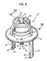
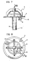
- the support 3 which is shown in greater detail in Figures 6 to 8, is constituted by a plastics body moulded in one piece with an annular flange 9 surmounted by four equiangularly-spaced arcuate elements 10 which terminate in a central hollow bearing part 11.
- the flange part 9 is formed with an internal annular valve seat 12 and two diametrally opposite legs 13, also moulded integrally, project from its face opposite the bearing part 11.
- the free ends of the legs 11 are formed with two internal notches 14 defined, at the ends of the legs 13, by respective tooth-shaped catches 15 which converge inwardly of the support 1.
- the flange part 9 may be provided with an air valve 16 constituted by a through-hole 17 and three integral appendages 18 which project axially from the same side as the legs 13 and between which a ball obturator 19 is movable, as shown in detail in Figure 9.
- the heat-sensitive element 2 is inserted coaxially in the support 3 with the free end of the reaction rod 5 engaged in the hollow bearing part 11 and the cylindrical casing 4 guided for axial sliding through a transverse bridge with a central centering and guide hole 21.
- the ends 22 of the transverse bridge 20 are of a shape complementary with that of the teeth 15 of the legs 13 of the support 3 and have respective depressions 23 as stiffeners and for preventing rotation.
- the ends 22 are inserted in the notches 14 and bear against the teeth 15.
- the transverse bridge 20 is kept in this bearing position by the compression spring 8 whose end remote from the obturator plate 6 bears against the bridge 20 near the central aperture 21.
- the spring 8 tends to urge the sealing edge 7 of the annular plate 6 against the annular valve seat 12 so that, in use, it closes the passage for the liquid through the valve 1.
- the heat-sensitive material in the casing 4 expands rapidly, exerting an axial force on the reaction rod 5. Since, as stated, the free end of the rod 5 is inserted in the bearing part 11, the casing 4 is translated axially, moving through the guide hole 21 in the transverse bridge 20 and compressing the spring 8. The plate 6 thus moves away from the valve seat 12, gradually opening the passage for the cooling liquid through the valve 1.
- the legs 13 of the support 3 are longer than in the previous embodiment and, at its end opposite the reaction rod 5, the casing 4 of the heat-sensitive element 2 has a shank 24 carrying a second plate obturator 25 for a by-pass valve, opposed by a helical compression spring 26.
Landscapes
- Engineering & Computer Science (AREA)
- Physics & Mathematics (AREA)
- Fluid Mechanics (AREA)
- General Physics & Mathematics (AREA)
- Automation & Control Theory (AREA)
- Chemical & Material Sciences (AREA)
- Combustion & Propulsion (AREA)
- Mechanical Engineering (AREA)
- General Engineering & Computer Science (AREA)
- Temperature-Responsive Valves (AREA)
- Heat-Pump Type And Storage Water Heaters (AREA)
Applications Claiming Priority (2)
| Application Number | Priority Date | Filing Date | Title |
|---|---|---|---|
| IT05343089U IT222295Z2 (it) | 1989-10-20 | 1989-10-20 | Valvola termostatica per la regolazione del flusso del liquido di raffreddamento di motori endotermici. |
| IT5343089U | 1989-10-20 |
Publications (2)
| Publication Number | Publication Date |
|---|---|
| EP0432103A2 true EP0432103A2 (de) | 1991-06-12 |
| EP0432103A3 EP0432103A3 (en) | 1992-12-16 |
Family
ID=11282691
Family Applications (1)
| Application Number | Title | Priority Date | Filing Date |
|---|---|---|---|
| EP19900830460 Withdrawn EP0432103A3 (en) | 1989-10-20 | 1990-10-16 | A thermostatic valve for regulating the flow of the cooling liquid in internal combustion engines |
Country Status (2)
| Country | Link |
|---|---|
| EP (1) | EP0432103A3 (de) |
| IT (1) | IT222295Z2 (de) |
Cited By (10)
| Publication number | Priority date | Publication date | Assignee | Title |
|---|---|---|---|---|
| FR2675878A1 (fr) * | 1991-04-23 | 1992-10-30 | Behr Thomson Dehnstoffregler | Soupape thermostatique. |
| FR2715208A1 (fr) * | 1994-01-18 | 1995-07-21 | Vincent Eric | Clapet ressort pour fluide. |
| FR2716519A1 (fr) * | 1994-02-18 | 1995-08-25 | Vernet Sa | Perfectionnement aux thermostats à boîtier intégré. |
| EP0681098A1 (de) * | 1994-05-07 | 1995-11-08 | Gustav Wahler GmbH u. Co | Thermostatventil |
| EP0810069A1 (de) * | 1996-05-28 | 1997-12-03 | QUINTON HAZELL plc | Bausatz zum Ersetzen von thermostatischen Ventilvorrichtungen |
| EP0825372A1 (de) * | 1996-08-19 | 1998-02-25 | Behr Thermot-tronik Italia S.p.A. | Thermostat-Ventilanordnung |
| CN102207023A (zh) * | 2010-03-29 | 2011-10-05 | 富士精工株式会社 | 恒温器装置 |
| WO2018093342A1 (en) * | 2016-11-18 | 2018-05-24 | Kirpart Otomotiv Parcalari Sanayi Ve Ticaret Anonim Sirketi | Thermostat assembly with self air bleeding valve |
| WO2019203758A3 (en) * | 2018-02-02 | 2020-02-06 | Kirpart Otomotiv Parcalari Sanayi Ve Ticaret A.S | Air venting valve formation method by fastening thermo-actuator inside valve structure without any additional operation or part and a thermostat assembly therefore |
| WO2023129032A1 (en) * | 2021-12-31 | 2023-07-06 | Kirpart Otomotiv Parcalari Sanayi Ve Ticaret Anonim Sirketi | A thermostat assembly with self-air bleeding valve structure, having unengaged lockable frames |
Citations (5)
| Publication number | Priority date | Publication date | Assignee | Title |
|---|---|---|---|---|
| FR1351153A (fr) * | 1963-03-15 | 1964-01-31 | Mecano Bundy Gmbh | Soupape thermostatique, en particulier pour radiateurs |
| FR1565568A (de) * | 1968-03-14 | 1969-05-02 | ||
| DE2239201A1 (de) * | 1972-08-09 | 1974-02-28 | Italiana Tubi Metall | Thermostatische vorrichtung zur steuerung des kuehlfluessigkeitsdurchflusses am ausgang einer brennkraftmaschine |
| FR2374579A1 (fr) * | 1976-12-18 | 1978-07-13 | Braukmann Armaturen | Soupape thermostatique, notamment pour circuit de refroidissement de moteur a combustion interne |
| US4300718A (en) * | 1980-04-10 | 1981-11-17 | Ford Motor Company | Engine cooling system air venting arrangement |
-
1989
- 1989-10-20 IT IT05343089U patent/IT222295Z2/it active IP Right Grant
-
1990
- 1990-10-16 EP EP19900830460 patent/EP0432103A3/en not_active Withdrawn
Patent Citations (5)
| Publication number | Priority date | Publication date | Assignee | Title |
|---|---|---|---|---|
| FR1351153A (fr) * | 1963-03-15 | 1964-01-31 | Mecano Bundy Gmbh | Soupape thermostatique, en particulier pour radiateurs |
| FR1565568A (de) * | 1968-03-14 | 1969-05-02 | ||
| DE2239201A1 (de) * | 1972-08-09 | 1974-02-28 | Italiana Tubi Metall | Thermostatische vorrichtung zur steuerung des kuehlfluessigkeitsdurchflusses am ausgang einer brennkraftmaschine |
| FR2374579A1 (fr) * | 1976-12-18 | 1978-07-13 | Braukmann Armaturen | Soupape thermostatique, notamment pour circuit de refroidissement de moteur a combustion interne |
| US4300718A (en) * | 1980-04-10 | 1981-11-17 | Ford Motor Company | Engine cooling system air venting arrangement |
Cited By (13)
| Publication number | Priority date | Publication date | Assignee | Title |
|---|---|---|---|---|
| FR2675878A1 (fr) * | 1991-04-23 | 1992-10-30 | Behr Thomson Dehnstoffregler | Soupape thermostatique. |
| FR2715208A1 (fr) * | 1994-01-18 | 1995-07-21 | Vincent Eric | Clapet ressort pour fluide. |
| FR2716519A1 (fr) * | 1994-02-18 | 1995-08-25 | Vernet Sa | Perfectionnement aux thermostats à boîtier intégré. |
| EP0681098A1 (de) * | 1994-05-07 | 1995-11-08 | Gustav Wahler GmbH u. Co | Thermostatventil |
| AU716092B2 (en) * | 1996-05-28 | 2000-02-17 | Quinton Hazell Automotive Limited | Kits for replacement of thermostatic valve assemblies |
| EP0810069A1 (de) * | 1996-05-28 | 1997-12-03 | QUINTON HAZELL plc | Bausatz zum Ersetzen von thermostatischen Ventilvorrichtungen |
| EP0825372A1 (de) * | 1996-08-19 | 1998-02-25 | Behr Thermot-tronik Italia S.p.A. | Thermostat-Ventilanordnung |
| CN102207023A (zh) * | 2010-03-29 | 2011-10-05 | 富士精工株式会社 | 恒温器装置 |
| EP2372124A3 (de) * | 2010-03-29 | 2013-08-07 | Fuji Bellows Co., Ltd. | Thermostatvorrichtung |
| CN102207023B (zh) * | 2010-03-29 | 2015-09-02 | 富士精工株式会社 | 恒温器装置 |
| WO2018093342A1 (en) * | 2016-11-18 | 2018-05-24 | Kirpart Otomotiv Parcalari Sanayi Ve Ticaret Anonim Sirketi | Thermostat assembly with self air bleeding valve |
| WO2019203758A3 (en) * | 2018-02-02 | 2020-02-06 | Kirpart Otomotiv Parcalari Sanayi Ve Ticaret A.S | Air venting valve formation method by fastening thermo-actuator inside valve structure without any additional operation or part and a thermostat assembly therefore |
| WO2023129032A1 (en) * | 2021-12-31 | 2023-07-06 | Kirpart Otomotiv Parcalari Sanayi Ve Ticaret Anonim Sirketi | A thermostat assembly with self-air bleeding valve structure, having unengaged lockable frames |
Also Published As
| Publication number | Publication date |
|---|---|
| IT8953430V0 (it) | 1989-10-20 |
| IT8953430U1 (it) | 1991-04-20 |
| EP0432103A3 (en) | 1992-12-16 |
| IT222295Z2 (it) | 1995-02-17 |
Similar Documents
| Publication | Publication Date | Title |
|---|---|---|
| EP0432103A2 (de) | Thermostatventil zur Regelung des Durchflusses des Kühlmittels für Brennkraftmaschinen | |
| US4055298A (en) | Thermally responsive by-pass valve device providing maximum flow area | |
| US5738276A (en) | Valve | |
| US20010002646A1 (en) | Multifunction rocker switch | |
| US4961530A (en) | Engine cooling system, structure therefor and methods of making the same | |
| US8827172B2 (en) | Thermostat valve | |
| US4562953A (en) | Valve seat structure for automotive thermostatic fluid control valve device | |
| US4089461A (en) | Thermostatic radiator valve | |
| US4257553A (en) | Valve construction and method of making the same | |
| US3045918A (en) | Actuator | |
| US3973729A (en) | Vent valve arrangement | |
| US3858800A (en) | Thermally responsive valve apparatus | |
| EP1752628B1 (de) | Thermostatventil für Schmierkreislauf eines Verbrennungsmotors eines Kraftfahrzeugs | |
| EP0947676A2 (de) | Kühlungsanlage für eine Brennkraftmaschine eines Kraftfahrzeuges | |
| GB2286675A (en) | Case for thermostat | |
| US3696997A (en) | Valve repsonsive to temperature changes over a limited range | |
| DK0666521T3 (da) | Termostatventil med forindstilling af gennemstrømningsmængden | |
| US4981260A (en) | Failsafe thermostat for water-cooled engines | |
| US4870944A (en) | Auxiliary air control valve for engine | |
| US3645443A (en) | Automobile thermostat | |
| US4353501A (en) | Fusible aquatic device that will override the failure of a defective thermostat or the like within a motor | |
| CA1273616A (en) | Thermostat with bypass valve | |
| DE4231649C2 (de) | Dreiwege-Thermostatventil für einen Kühl- bzw. Heizkreislauf eines Automobils | |
| JP2581274Y2 (ja) | 開弁温度可変式サーモスタット | |
| CA1077906A (en) | Thermostatic radiator valve |
Legal Events
| Date | Code | Title | Description |
|---|---|---|---|
| PUAI | Public reference made under article 153(3) epc to a published international application that has entered the european phase |
Free format text: ORIGINAL CODE: 0009012 |
|
| AK | Designated contracting states |
Kind code of ref document: A2 Designated state(s): AT BE CH DE DK ES FR GB GR IT LI LU NL SE |
|
| PUAL | Search report despatched |
Free format text: ORIGINAL CODE: 0009013 |
|
| AK | Designated contracting states |
Kind code of ref document: A3 Designated state(s): AT BE CH DE DK ES FR GB GR IT LI LU NL SE |
|
| STAA | Information on the status of an ep patent application or granted ep patent |
Free format text: STATUS: THE APPLICATION IS DEEMED TO BE WITHDRAWN |
|
| 18D | Application deemed to be withdrawn |
Effective date: 19930617 |