EP0432054A2 - Elektronischer Schutzschalter mit als Flachanzeige ausgebildeter Frontfläche - Google Patents
Elektronischer Schutzschalter mit als Flachanzeige ausgebildeter Frontfläche Download PDFInfo
- Publication number
- EP0432054A2 EP0432054A2 EP90420477A EP90420477A EP0432054A2 EP 0432054 A2 EP0432054 A2 EP 0432054A2 EP 90420477 A EP90420477 A EP 90420477A EP 90420477 A EP90420477 A EP 90420477A EP 0432054 A2 EP0432054 A2 EP 0432054A2
- Authority
- EP
- European Patent Office
- Prior art keywords
- trigger
- display device
- display
- type
- memory
- Prior art date
- Legal status (The legal status is an assumption and is not a legal conclusion. Google has not performed a legal analysis and makes no representation as to the accuracy of the status listed.)
- Granted
Links
Images

Classifications
-
- H—ELECTRICITY
- H02—GENERATION; CONVERSION OR DISTRIBUTION OF ELECTRIC POWER
- H02H—EMERGENCY PROTECTIVE CIRCUIT ARRANGEMENTS
- H02H3/00—Emergency protective circuit arrangements for automatic disconnection directly responsive to an undesired change from normal electric working condition with or without subsequent reconnection ; integrated protection
- H02H3/006—Calibration or setting of parameters
Definitions
- the invention relates to an electronic trip device comprising an electronic processing assembly, comprising a microprocessor and at least one backed-up random access memory, receiving output signals from means for measuring the current flowing through the conductors to be protected and intended to produce a trip signal in cases of predetermined trigger parameters being exceeded by said signals, a front panel comprising indications relating to the type of trigger, means for signaling a fault, and a display device intended to display the trigger parameters and / or various quantities measured by the trigger.
- the front face of the trigger comprises at least means for signaling a fault, generally in the form of an indicator light, electromechanical means, potentiometers, switches or keys, making it possible to adjust the thresholds of release, and a label on which are printed the information relating to the manufacturer and type of release.
- a display device is provided for displaying measured values and / or trigger parameters (EP 279,691).
- the number of different labels that can be associated with a trigger can be very high, on the order of a hundred, due to the large number of possible options.
- the object of the invention is to standardize the triggers, without limiting the number of possible options and by eliminating if possible any risk of error of adequacy between the label disposed on the front face of the trigger and the functions actually performed by the trigger.
- the front face of the trigger consists of a flat screen display device, controlled by the microprocessor and connected to an internal battery so as to permanently display various data contained in the memory and constituted at least at the same time by indications relating to the type of trigger, by the trigger parameters and by the signaling of a fault, the trigger comprising reception means connected to the microprocessor and intended to cooperate with means of transmission of a remote control device comprising means for remotely modifying the trigger parameters contained in the memory.
- the label and the signaling devices on the front face are replaced by a liquid crystal display controlled by the microprocessor of the release.
- This display preferably occupies the entire front face.
- the information displayed must correspond to the data in the memory which is taken into account by the trigger during signal processing.
- a single standard display replaces the various labels hitherto necessary to personalize a trigger according to the various possible options.
- the display is preferably a liquid crystal display.
- a remote control to modify the trigger parameters makes it possible to exclude any electromechanical element, potentiometer, switch or key, from the front face of the trigger. This essentially eliminates the problems of electrostatic discharges.
- the processing assembly can then be placed on one (or more) printed circuit board which, in the absence of mechanical parts, can be covered with varnish, thereby improving the response of the assembly to climatic constraints.
- the elimination of these electromechanical elements also allows a significant gain in volume on the printed circuit boards.
- the indications relating to the type of trigger are introduced into the remote memory by means of a specific remote control device, and preferably these indications cannot be modified subsequently, after their introduction into the memory.
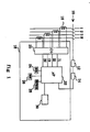
- a three-phase electrical distribution network comprising three phase conductors 1,2,3 and a neutral conductor N comprises a circuit breaker 10 capable of interrupting the circuit in the open position.
- the mechanism 12 of the circuit breaker 10 is controlled by a polarized relay 14 for controlling tripping of the circuit breaker in the event of an overload or a short circuit.
- Each conductor (1,2,3, N) is associated with a current transformer 16 which delivers an analog signal representative of the current flowing through the associated conductor.
- These signals are applied to the trigger 18 which includes a rectification and shaping circuit 20, the outputs I1, I2, I3 and IN of which are applied to an electronic processing unit with microprocessor 22, one output of which controls the polarized relay 14.
- the microprocessor is connected to various auxiliaries (not shown) necessary for its operation, and to at least one read-only memory (ROM) 24 and a random access memory (RAM) 26.
- ROM read-only memory
- RAM random access memory
- the microprocessor is connected to a third memory 28, which is a backed-up random access memory or, preferably, an electrically erasable programmable read-only memory (EEPROM or NOVRAM).
- EEPROM or NOVRAM electrically erasable programmable read-only memory
- the microprocessor is, moreover, connected to a display device 30.
- the trip device provides, in a known manner, various protection functions when a fault or an overload appears in the distribution network to be protected.
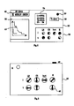
- the front face of the trigger 18, arranged so as to be seen by a user is constituted by the front face of the display device 30, the latter being a display of the liquid crystal type.
- this information is represented by a combination of alphanumeric signs (LR, CR, Inst, H, I, t) and diagrams of analog type, in the form of circular segments, corresponding to a graphical representation of potentiometers or switches.
- Other zones, 34 and 36, of the display device can be used to display measured values, for example phase (I1, I2, I3) and neutral (IN) currents as well as temperature (T ).
- the display also indicates a certain amount of information representative of the type of trigger.
- this information is both of the alphanumeric type (ST 2000, parameters of zone 32 corresponding to the functions actually performed by the trigger) and graphic type like the trigger curves (zone 38).
- the signaling of a fault is also carried out by the display.
- a point 40 located on the long delay tripping curve indicates tripping due to a long delay fault.
- This same point for example by flashing, can also be used to signal an overshoot of the long delay threshold which has not yet led to a trip.
- the front face of the trigger 18 thus comprises, on the display device 30, all the information concerning the trigger which interests a user.
- the information is displayed under the control of the microprocessor, the various information to be displayed being contained in the memory 28 (EEPROM). If the trip device is a trip device with its own current, that is to say powered by the network to be protected, there is provided in the trip device a battery or an auxiliary battery so as to keep the display even when the circuit breaker is open.
- the displayed data corresponding to the data stored in the trigger and used by the microprocessor to perform the various protection functions provided in a particular trigger there is no risk of error of adequacy between the information displayed on the face before the trigger and the functions actually performed by the trigger.
- there is no risk that the type of trigger and the trigger curves do not correspond to the type of trigger actually used whereas such an error was possible in the triggers according to the prior art where a label was glued to the front of the trigger during its manufacture.
- the front of the trigger does not have a potentiometer, switch or button, allowing modification of the trigger parameters.
- an infrared link makes it possible to modify the triggering parameters from a remote control device 44.
- the remote control device 44 includes a plurality of potentiometers 46 making it possible to adjust the various trigger parameters.
- This device is preferably constituted by a standard box comprising as many potentiometers, switches or keys, as it is necessary to modify the triggering parameters of a trigger comprising the maximum of possible options.
- a transmission key M causes the transmission of the corresponding data, via a transmitter 48 of the remote control device and a receiver 50 arranged on the front face of the trigger. The reception of data by the receiver 50, connected to the microprocessor of the trip device, leads to the modification of the parameter concerned in the memory 28 and, consequently, in the area 32 of the display 30.
- the same standard remote control unit 44 can be used to successively set several triggers.
- FIG. 4 illustrates a remote control device 52 intended to configure the trip device, that is to say to determine the options which it must perform.
- the device 52 includes a switch with three positions D, S and G, making it possible to select three types of curves separately.
- a number of two-position switches allow you to determine whether or not a trip unit should include corresponding options, for example a zero sequence trip function (H), signaling the type of fault ( F), a relesting function (R).
- H zero sequence trip function
- F signaling the type of fault
- R relesting function
- the remote control device 52 communicates with the trigger via an infrared link, a transmitter 48 cooperating with the receiver 50 of the trigger.
- the configuration of the trigger is preferably carried out at the end of manufacture.
- the switches corresponding to the options selected for a particular trigger are set to the ON position and the emission key M of the remote control device is pressed, causing the corresponding data to be transmitted to the trigger.
- the trigger microprocessor puts this data in memory, in memory 28, and uses this stored data to determine which subroutines contained in the read-only memory 24 it should use when processing the data.
- the stored data is also used to determine the type of information to be displayed.
- the trigger does not have to perform a shedding function
- the switch corresponding to option R of the remote control device being in the OFF position when the trigger is configured, the graphic representation of the switch R does not appear not in area 32 of the display. The user thus knows exactly what are the functions performed by the trigger and the actuation of the corresponding potentiometer R of the remote control device 44 has no influence on the trigger.
- FIG. 5 illustrates another embodiment of the display 30.
- the signaling of the faults is carried out by means of dots 54, arranged opposite the graphic representations 56 of the potentiometers corresponding to the different triggering functions.
- the point associated with the long delay function is blackened, indicating that a long delay trigger has occurred.
- the display can also be produced by a plasma display.
- Information that is common to all triggers whatever the type, such as the manufacturer's logo and name or the coordinates of trigger curves, can be integrated into the liquid crystal display so as to be visible in permanently, even in the absence of a battery. This is achieved, in known manner, by interposing under the front face of the display a transparent plate on which this information is printed.
- the infrared link can also be replaced by any other type of link, for example by a radio link, an ultrasonic link, or even by a two-wire line.
- Remote control devices may have buttons in place of or in addition to the potentiometers.
- the remote control device can optionally be replaced by a conventional microcomputer, connected to the trigger by a two-wire line. In this case, the data are selected and displayed on the microcomputer and transmitted by the line to the microprocessor of the trigger which displays them and uses them later for processing. This latter type of remote control is more particularly suitable for configuring the trigger at the end of the chain.
Landscapes
- Control Of Indicators Other Than Cathode Ray Tubes (AREA)
- Selective Calling Equipment (AREA)
- Emergency Protection Circuit Devices (AREA)
Applications Claiming Priority (2)
| Application Number | Priority Date | Filing Date | Title |
|---|---|---|---|
| FR8915155 | 1989-11-16 | ||
| FR8915155A FR2654539B1 (fr) | 1989-11-16 | 1989-11-16 | Declencheur electronique dont la face avant est constituee par un afficheur a ecran plat. |
Publications (3)
| Publication Number | Publication Date |
|---|---|
| EP0432054A2 true EP0432054A2 (de) | 1991-06-12 |
| EP0432054A3 EP0432054A3 (en) | 1991-07-24 |
| EP0432054B1 EP0432054B1 (de) | 1994-10-12 |
Family
ID=9387531
Family Applications (1)
| Application Number | Title | Priority Date | Filing Date |
|---|---|---|---|
| EP90420477A Expired - Lifetime EP0432054B1 (de) | 1989-11-16 | 1990-11-06 | Elektronischer Schutzschalter mit als Flachanzeige ausgebildeter Frontfläche |
Country Status (5)
| Country | Link |
|---|---|
| US (1) | US5220479A (de) |
| EP (1) | EP0432054B1 (de) |
| CA (1) | CA2029740A1 (de) |
| DE (1) | DE69013302T2 (de) |
| FR (1) | FR2654539B1 (de) |
Cited By (7)
| Publication number | Priority date | Publication date | Assignee | Title |
|---|---|---|---|---|
| EP0537084A1 (de) * | 1991-10-10 | 1993-04-14 | Schneider Electric Sa | Schutzschalter mit selektiver Verriegelung |
| EP0589347A2 (de) * | 1992-09-16 | 1994-03-30 | Hitachi, Ltd. | Ausschalter und Verfahren zu seiner Kontrolle |
| WO1994007254A1 (en) * | 1992-09-14 | 1994-03-31 | Nu-Lec Pty Ltd | A memory or signature circuit for switchgear |
| EP0634825A2 (de) * | 1993-07-15 | 1995-01-18 | Eaton Corporation | Überstromauslöseeinheit mit Anzeige der Auslösebedingungen |
| US5675754A (en) * | 1994-09-30 | 1997-10-07 | Siemens Energy & Automation, Inc. | Graphical display for an energy management device |
| WO1999046841A1 (de) * | 1998-03-13 | 1999-09-16 | Siemens Aktiengesellschaft | Elektronischer auslöser mit einstell- und anzeigeelementen |
| WO2009043766A1 (de) * | 2007-09-26 | 2009-04-09 | Siemens Aktiengesellschaft | Steuerung der anzeigehintergrundbeleuchtung bei einem leistungsschalter |
Families Citing this family (23)
| Publication number | Priority date | Publication date | Assignee | Title |
|---|---|---|---|---|
| US5485343A (en) * | 1994-02-22 | 1996-01-16 | General Electric Company | Digital circuit interrupter with battery back-up facility |
| US5500781A (en) * | 1994-05-09 | 1996-03-19 | General Electric Company | Digital circuit interrupter with multiple accessory function |
| GB2290182B (en) * | 1994-06-10 | 1998-09-09 | Gen Electric | Cicuit interrupter |
| US5745114A (en) * | 1994-09-30 | 1998-04-28 | Siemens Energy & Automation, Inc. | Graphical display for an energy management device |
| US5517381A (en) * | 1994-11-23 | 1996-05-14 | Guim; Raul | Circuit breaker counter indicator |
| US5987393A (en) * | 1997-02-20 | 1999-11-16 | Abb Power T&D Company Inc. | Method of configuring a microprocessor-based relay for use in overcurrent protection |
| US6385022B1 (en) * | 1999-06-03 | 2002-05-07 | General Electric Company | Method and apparatus for deriving power system data from configurable source points |
| FR2798525B1 (fr) | 1999-09-09 | 2001-11-02 | Schneider Electric Ind Sa | Declencheur electronique comportant un dispositif d'initialisation |
| FR2798524B1 (fr) | 1999-09-13 | 2001-11-02 | Schneider Electric Ind Sa | Declencheur comportant une interface homme-machine amelioree et disjoncteur comportant un tel dispositif |
| US6552884B2 (en) * | 2000-05-12 | 2003-04-22 | Human El Tech, Inc. | Circuit breaker with display function |
| US6798209B2 (en) * | 2002-01-17 | 2004-09-28 | General Electric Company | Circuit breaker with integral testing unit |
| ATE371289T1 (de) * | 2002-02-12 | 2007-09-15 | Abb Schweiz Ag | Empfang von schutzbefehlen in einem fernauslösegerät |
| US7030769B2 (en) * | 2003-11-13 | 2006-04-18 | Eaton Corporation | Monitor providing cause of trip indication and circuit breaker incorporating the same |
| DE102005016105A1 (de) * | 2005-04-08 | 2006-10-12 | Moeller Gmbh | Verfahren zum Ein- und Darstellen der Auslösekennlinie von Schutzschaltern |
| US7633736B2 (en) * | 2006-06-23 | 2009-12-15 | Eaton Corporation | Circuit interrupter including nonvolatile memory storing cause-of-trip information |
| US7697250B2 (en) * | 2006-07-14 | 2010-04-13 | William Davison | Switch-to-trip point translation |
| US7995314B2 (en) * | 2007-12-03 | 2011-08-09 | Siemens Industry, Inc. | Devices, systems, and methods for managing a circuit breaker |
| US8675325B2 (en) * | 2010-10-20 | 2014-03-18 | Schneider Electric USA, Inc. | Electronic circuit breaker with alternate mode of operation using auxiliary power source |
| US8503148B2 (en) * | 2010-10-20 | 2013-08-06 | Schneider Electric USA, Inc. | Circuit breaker with fault indication and secondary power supply |
| GB2490167A (en) | 2011-04-21 | 2012-10-24 | Pz Cussons Int Ltd | Hair styling system |
| US9331746B2 (en) * | 2012-12-19 | 2016-05-03 | Eaton Corporation | System and method for providing information to and/or obtaining information from a component of an electrical distribution system |
| WO2019207459A1 (en) * | 2018-04-23 | 2019-10-31 | Abb Schweiz Ag | A device for displaying breaker related data in real-time and a method thereof |
| DE102018211646B4 (de) * | 2018-07-12 | 2022-12-15 | Siemens Aktiengesellschaft | Niederspannungsleistungsschalter und Verfahren |
Citations (7)
| Publication number | Priority date | Publication date | Assignee | Title |
|---|---|---|---|---|
| US4266105A (en) * | 1979-01-15 | 1981-05-05 | Gould Inc. | Biasing means for combination actuator |
| US4429340A (en) * | 1981-03-25 | 1984-01-31 | General Electric Co. | Bargraph displays for static trip circuit breakers |
| EP0226530A2 (de) * | 1985-11-08 | 1987-06-24 | Siemens Aktiengesellschaft | Anzeigeeinrichtung für den Auslösestatus eines Niederspannungs-Leistungsschalters |
| EP0232654A1 (de) * | 1986-01-03 | 1987-08-19 | Merlin Gerin | Leser für einen numerischen Auslöser in einem Schutzschalter |
| JPS62280655A (ja) * | 1986-05-29 | 1987-12-05 | Shikoku Electric Power Co Inc | 電子式電力量計 |
| EP0279691A2 (de) * | 1987-02-20 | 1988-08-24 | Westinghouse Electric Corporation | Ausschalter mit einer auswählbaren Anzeige |
| US4870531A (en) * | 1988-08-15 | 1989-09-26 | General Electric Company | Circuit breaker with removable display and keypad |
Family Cites Families (4)
| Publication number | Priority date | Publication date | Assignee | Title |
|---|---|---|---|---|
| FR2602610B1 (fr) * | 1986-08-08 | 1994-05-20 | Merlin Et Gerin | Declencheur statique d'un disjoncteur electrique a indicateur d'usure des contacts |
| JPH0834705B2 (ja) * | 1988-11-16 | 1996-03-29 | 株式会社大林組 | 開閉器 |
| US5038246A (en) * | 1989-08-31 | 1991-08-06 | Square D Company | Fault powered, processor controlled circuit breaker trip system having reliable tripping operation |
| US4991042A (en) * | 1990-03-19 | 1991-02-05 | General Electric Company | Digital circuit interrupter with keypad data entry and display |
-
1989
- 1989-11-16 FR FR8915155A patent/FR2654539B1/fr not_active Expired - Fee Related
-
1990
- 1990-11-06 EP EP90420477A patent/EP0432054B1/de not_active Expired - Lifetime
- 1990-11-06 DE DE69013302T patent/DE69013302T2/de not_active Expired - Fee Related
- 1990-11-09 US US07/611,776 patent/US5220479A/en not_active Expired - Lifetime
- 1990-11-13 CA CA002029740A patent/CA2029740A1/en not_active Abandoned
Patent Citations (7)
| Publication number | Priority date | Publication date | Assignee | Title |
|---|---|---|---|---|
| US4266105A (en) * | 1979-01-15 | 1981-05-05 | Gould Inc. | Biasing means for combination actuator |
| US4429340A (en) * | 1981-03-25 | 1984-01-31 | General Electric Co. | Bargraph displays for static trip circuit breakers |
| EP0226530A2 (de) * | 1985-11-08 | 1987-06-24 | Siemens Aktiengesellschaft | Anzeigeeinrichtung für den Auslösestatus eines Niederspannungs-Leistungsschalters |
| EP0232654A1 (de) * | 1986-01-03 | 1987-08-19 | Merlin Gerin | Leser für einen numerischen Auslöser in einem Schutzschalter |
| JPS62280655A (ja) * | 1986-05-29 | 1987-12-05 | Shikoku Electric Power Co Inc | 電子式電力量計 |
| EP0279691A2 (de) * | 1987-02-20 | 1988-08-24 | Westinghouse Electric Corporation | Ausschalter mit einer auswählbaren Anzeige |
| US4870531A (en) * | 1988-08-15 | 1989-09-26 | General Electric Company | Circuit breaker with removable display and keypad |
Non-Patent Citations (1)
| Title |
|---|
| PATENT ABSTRACTS OF JAPAN vol. 12, no. 166 (P-704)(3013), 19 mai 1988; & JP - A - 62280655 (SHIKOKU ELECTRIC POWER) 05.12.1987 * |
Cited By (10)
| Publication number | Priority date | Publication date | Assignee | Title |
|---|---|---|---|---|
| EP0537084A1 (de) * | 1991-10-10 | 1993-04-14 | Schneider Electric Sa | Schutzschalter mit selektiver Verriegelung |
| FR2682529A1 (fr) * | 1991-10-10 | 1993-04-16 | Merlin Gerin | Disjoncteur a verrouillage selectif. |
| WO1994007254A1 (en) * | 1992-09-14 | 1994-03-31 | Nu-Lec Pty Ltd | A memory or signature circuit for switchgear |
| EP0589347A2 (de) * | 1992-09-16 | 1994-03-30 | Hitachi, Ltd. | Ausschalter und Verfahren zu seiner Kontrolle |
| EP0589347A3 (de) * | 1992-09-16 | 1994-11-17 | Hitachi Ltd | Ausschalter und Verfahren zu seiner Kontrolle. |
| EP0634825A2 (de) * | 1993-07-15 | 1995-01-18 | Eaton Corporation | Überstromauslöseeinheit mit Anzeige der Auslösebedingungen |
| EP0634825A3 (de) * | 1993-07-15 | 1997-03-05 | Eaton Corp | Überstromauslöseeinheit mit Anzeige der Auslösebedingungen. |
| US5675754A (en) * | 1994-09-30 | 1997-10-07 | Siemens Energy & Automation, Inc. | Graphical display for an energy management device |
| WO1999046841A1 (de) * | 1998-03-13 | 1999-09-16 | Siemens Aktiengesellschaft | Elektronischer auslöser mit einstell- und anzeigeelementen |
| WO2009043766A1 (de) * | 2007-09-26 | 2009-04-09 | Siemens Aktiengesellschaft | Steuerung der anzeigehintergrundbeleuchtung bei einem leistungsschalter |
Also Published As
| Publication number | Publication date |
|---|---|
| EP0432054B1 (de) | 1994-10-12 |
| FR2654539B1 (fr) | 1994-04-08 |
| DE69013302T2 (de) | 1995-06-01 |
| FR2654539A1 (fr) | 1991-05-17 |
| CA2029740A1 (en) | 1991-05-17 |
| US5220479A (en) | 1993-06-15 |
| EP0432054A3 (en) | 1991-07-24 |
| DE69013302D1 (de) | 1994-11-17 |
Similar Documents
| Publication | Publication Date | Title |
|---|---|---|
| EP0432054B1 (de) | Elektronischer Schutzschalter mit als Flachanzeige ausgebildeter Frontfläche | |
| EP1085633B1 (de) | Auslöser mit verbesserter Mensch-Maschine Schnittstelle und Schutzschalter mit einem solchen Auslöser | |
| FR2480523A1 (fr) | Appareil coupe-circuit a affichage et entree de parametres multiples | |
| EP0843332B1 (de) | Lastschalter mit einem Leistungsschalterblock mit Bearbeitungs-Modul, Kalibrierungs-Modul und Anzeige-Modul | |
| EP0537084B1 (de) | Schutzschalter mit selektiver Verriegelung | |
| US6788512B2 (en) | Electronic trip unit capable of analog and digital setting of circuit breaker setpoints | |
| FR2480514A1 (fr) | Appareil coupe-circuit comportant un dispositif de declenchement de depassement de temperature | |
| FR2480520A1 (fr) | Appareil coupe-circuit a fonctions de gestion de l'energie | |
| FR2480521A1 (fr) | Appareil coupe-circuit a unite de declenchement numerique et a alimentation | |
| EP0923185B1 (de) | Elektrische Unterbrechungsvorrichtung mit einem Kommunikationsmodul | |
| FR2480516A1 (de) | ||
| FR2480515A1 (fr) | Appareil coupe-circuit a indicateur a distance et a alimentation | |
| CA2128132A1 (en) | Overcurrent trip unit with indication of dependency of trip functions | |
| FR2480518A1 (fr) | Appareil de coupe-circuit a unite de declenchement numerique et circuit designateur | |
| FR2638565A1 (fr) | Declencheur a microprocesseur a fonctions optionnelles et procede de selection desdites fonctions | |
| FR2541008A1 (fr) | Systeme pour controler le fonctionnement des transducteurs de sortie d'une unite centrale de commande et de controle pour des machines et/ou des dispositifs utilisables dans des lignes de production et/ou des lignes d'emballage de produits | |
| EP1005130B1 (de) | Auslöser mit mehreren Einstelleinrichtungen für die Schutzparameter | |
| WO2012146619A1 (fr) | Système de protection et de supervision d'un circuit de distribution d'énergie électrique à courant continu | |
| FR2480519A1 (fr) | Appareil coupe-circuit a unite de declenchement numerique et moyen d'introduction de valeur de reglage | |
| EP0536058B2 (de) | Elektronischer Auslöser mit lokale den detektierten Fehler anzeigende Mittel | |
| EP3552034B1 (de) | Verfahren zur herstellung eines messsensors für einen leistungsschalter | |
| EP0342101A1 (de) | Testschaltung für eine Sicherung eines Geräts zur Messung der Stromstärke | |
| FR2760147A1 (fr) | Dispositif de declenchement electronique pour disjoncteur | |
| EP0399983B1 (de) | "Not-Aus"-Einrichtung für Industrieinstallation | |
| BE1010688A7 (fr) | Interrupteur differentiel. |
Legal Events
| Date | Code | Title | Description |
|---|---|---|---|
| PUAI | Public reference made under article 153(3) epc to a published international application that has entered the european phase |
Free format text: ORIGINAL CODE: 0009012 |
|
| PUAL | Search report despatched |
Free format text: ORIGINAL CODE: 0009013 |
|
| AK | Designated contracting states |
Kind code of ref document: A2 Designated state(s): BE CH DE ES GB IT LI SE |
|
| AK | Designated contracting states |
Kind code of ref document: A3 Designated state(s): BE CH DE ES GB IT LI SE |
|
| 17P | Request for examination filed |
Effective date: 19920115 |
|
| 17Q | First examination report despatched |
Effective date: 19931229 |
|
| GRAA | (expected) grant |
Free format text: ORIGINAL CODE: 0009210 |
|
| AK | Designated contracting states |
Kind code of ref document: B1 Designated state(s): BE CH DE ES GB IT LI SE |
|
| PG25 | Lapsed in a contracting state [announced via postgrant information from national office to epo] |
Ref country code: ES Free format text: THE PATENT HAS BEEN ANNULLED BY A DECISION OF A NATIONAL AUTHORITY Effective date: 19941012 |
|
| REF | Corresponds to: |
Ref document number: 69013302 Country of ref document: DE Date of ref document: 19941117 |
|
| ITF | It: translation for a ep patent filed |
Owner name: EUROPATENT S.A.S. |
|
| GBT | Gb: translation of ep patent filed (gb section 77(6)(a)/1977) |
Effective date: 19941208 |
|
| PG25 | Lapsed in a contracting state [announced via postgrant information from national office to epo] |
Ref country code: SE Effective date: 19950112 |
|
| PLBE | No opposition filed within time limit |
Free format text: ORIGINAL CODE: 0009261 |
|
| STAA | Information on the status of an ep patent application or granted ep patent |
Free format text: STATUS: NO OPPOSITION FILED WITHIN TIME LIMIT |
|
| 26N | No opposition filed | ||
| PGFP | Annual fee paid to national office [announced via postgrant information from national office to epo] |
Ref country code: CH Payment date: 19961121 Year of fee payment: 7 |
|
| PGFP | Annual fee paid to national office [announced via postgrant information from national office to epo] |
Ref country code: BE Payment date: 19961230 Year of fee payment: 7 |
|
| PG25 | Lapsed in a contracting state [announced via postgrant information from national office to epo] |
Ref country code: CH Free format text: LAPSE BECAUSE OF NON-PAYMENT OF DUE FEES Effective date: 19971130 Ref country code: LI Free format text: LAPSE BECAUSE OF NON-PAYMENT OF DUE FEES Effective date: 19971130 Ref country code: BE Free format text: LAPSE BECAUSE OF NON-PAYMENT OF DUE FEES Effective date: 19971130 |
|
| BERE | Be: lapsed |
Owner name: MERLIN GERIN Effective date: 19971130 |
|
| REG | Reference to a national code |
Ref country code: CH Ref legal event code: PL |
|
| PGFP | Annual fee paid to national office [announced via postgrant information from national office to epo] |
Ref country code: GB Payment date: 19991103 Year of fee payment: 10 |
|
| PG25 | Lapsed in a contracting state [announced via postgrant information from national office to epo] |
Ref country code: GB Free format text: LAPSE BECAUSE OF NON-PAYMENT OF DUE FEES Effective date: 20001106 |
|
| GBPC | Gb: european patent ceased through non-payment of renewal fee |
Effective date: 20001106 |
|
| PG25 | Lapsed in a contracting state [announced via postgrant information from national office to epo] |
Ref country code: IT Free format text: LAPSE BECAUSE OF NON-PAYMENT OF DUE FEES;WARNING: LAPSES OF ITALIAN PATENTS WITH EFFECTIVE DATE BEFORE 2007 MAY HAVE OCCURRED AT ANY TIME BEFORE 2007. THE CORRECT EFFECTIVE DATE MAY BE DIFFERENT FROM THE ONE RECORDED. Effective date: 20051106 |
|
| PGFP | Annual fee paid to national office [announced via postgrant information from national office to epo] |
Ref country code: DE Payment date: 20071109 Year of fee payment: 18 |
|
| PG25 | Lapsed in a contracting state [announced via postgrant information from national office to epo] |
Ref country code: DE Free format text: LAPSE BECAUSE OF NON-PAYMENT OF DUE FEES Effective date: 20090603 |