EP0342101A1 - Testschaltung für eine Sicherung eines Geräts zur Messung der Stromstärke - Google Patents
Testschaltung für eine Sicherung eines Geräts zur Messung der Stromstärke Download PDFInfo
- Publication number
- EP0342101A1 EP0342101A1 EP89401252A EP89401252A EP0342101A1 EP 0342101 A1 EP0342101 A1 EP 0342101A1 EP 89401252 A EP89401252 A EP 89401252A EP 89401252 A EP89401252 A EP 89401252A EP 0342101 A1 EP0342101 A1 EP 0342101A1
- Authority
- EP
- European Patent Office
- Prior art keywords
- fuse
- threshold circuit
- current
- state
- resistor
- Prior art date
- Legal status (The legal status is an assumption and is not a legal conclusion. Google has not performed a legal analysis and makes no representation as to the accuracy of the status listed.)
- Withdrawn
Links
Images
Classifications
-
- G—PHYSICS
- G01—MEASURING; TESTING
- G01R—MEASURING ELECTRIC VARIABLES; MEASURING MAGNETIC VARIABLES
- G01R1/00—Details of instruments or arrangements of the types included in groups G01R5/00 - G01R13/00 and G01R31/00
- G01R1/36—Overload-protection arrangements or circuits for electric measuring instruments
-
- G—PHYSICS
- G01—MEASURING; TESTING
- G01R—MEASURING ELECTRIC VARIABLES; MEASURING MAGNETIC VARIABLES
- G01R31/00—Arrangements for testing electric properties; Arrangements for locating electric faults; Arrangements for electrical testing characterised by what is being tested not provided for elsewhere
- G01R31/50—Testing of electric apparatus, lines, cables or components for short-circuits, continuity, leakage current or incorrect line connections
- G01R31/74—Testing of fuses
Definitions
- the present invention relates to a current intensity measuring device comprising first and second input terminals, a fuse and a shunt resistor connected in series between said input terminals, and a measurement circuit connected to the terminals of the shunt resistance.
- means are generally provided to protect the device in the event of an excessive current value. Such a situation can for example occur in the event of an error in the connection of the device, for example when the user performs a voltage measurement while the function selector of the device has remained in a position corresponding to a measurement. intensity.
- This protection means is, in many cases, constituted by a fuse in series with the shunt resistance traversed by the current to be measured.
- One solution to solve this problem may consist in using, if it exists, the ohmmeter function of the measuring device. Not only is this solution not always possible, but even when the device is equipped with an ohmmeter function, this solution requires the user to make switches, and it involves the risk of false operations during which can be dangerous both for the measuring device and for the user.
- the present invention therefore aims to inform the user of a current measuring device of the state of the device fuse, as soon as it is started, without the user having to carry out other operations than those of the on / off button of the measuring device.
- the measuring device of the present invention is characterized in that the first input terminal is connected to a fixed potential point via a resistor having a high ohmic value compared to that of the shunt resistor, and in that the two input terminals are connected to a threshold circuit producing on its output a signal having a first state when the fuse is in good condition, and a second state when the fuse is cut.
- the fixed potential point can for example be a point which is at the supply potential of the measuring device when the on / off switch of the latter is in the on position.
- the threshold circuit provides on its output a signal which is representative of the good or bad state of the fuse of the measuring device.
- the latter may then include a visual and / or audible alarm means, which is activated in response to the second state of the output signal from the threshold circuit.
- the measuring device includes a display, for example a liquid crystal display
- the latter may include a display area which, when activated, indicates an error or alarm condition.
- the display can be connected to the output of the threshold circuit, so that said display area is activated in response to the second state of the output signal of the threshold circuit.
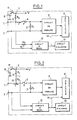
- the current measurement device shown in FIG. 1 comprises two input terminals 1 and 2, terminal 1 corresponding to the hot spot of the measurement.
- Terminal 1 is connected to one end of the shunt 3 of the measuring device via a fuse 4, the other end of the shunt 3 being connected to the input terminal 2.
- the voltage which appears at the terminals of the shunt 3 and which is proportional to the current I to be measured is conventionally measured by a measurement circuit 5 and the value of the current I to be measured is conventionally indicated by an indicating device 6, which can be of any known type (dial and needle indicator, quantified digital and / or analog display with electroluminescent electrodes or with liquid crystals, etc.).
- terminal 1 is also connected to a point 7 of fixed potential V via a resistor 8 of high value.
- the point 7 can be a point which is at the potential of the power source 9 of the measuring device when the on / off switch 11 of the latter is closed.
- a voltage appears on the input terminal 1. which can take one or the other of two values according to the state of the fuse 4. More precisely, if the fuse 4 is in good condition, it appears on the terminal input 1 a voltage V (r + r0) / (R1 + r + r0), where V is the fixed potential at point 7 and r0, r and R1 are the ohmic values of shunt 3, fuse 4 and resistance 8. By cons, if fuse 4 is cut, it appears on terminal 1 a voltage equal to potential V.
- the value R1 of the resistor 8 must also be chosen in such a way that if, in service, the input terminal 1 is itself at a relatively high potential as a result of the connection of the measuring device in a circuit traversed by a current to be measured, and if the fuse 4 blows due to an excessive current, the current which is then diverted towards the power source 9 through the resistor 8 is as low as possible. This is why, although, strictly from the point of view of the precision of the measurement, it would suffice that R1 is 100 or 1000 times greater than r0, in practice we will choose an even greater resistance R1.
- R1 a value at least equal to 104 ⁇ .
- the parasitic voltage across the terminals of shunt 3 is then at most equal to 9.10 ⁇ 6 volts, which is perfectly negligible .
- the input terminal 1 is at a relatively high potential, for example 380V
- the current which would be diverted to the power source 9 through the resistor 8 in the event of a fuse 4 breaking would then be at most equal to 38mA.
- the voltage between terminals 1 and 2 is applied to a threshold circuit 12 which can be of any known type.
- the threshold circuit can for example be constituted by a Schmidt flip-flop or, if the measuring device includes a microprocessor, it can then advantageously be constituted by an input port of the microprocessor. In the latter case, the microprocessor can be programmed to carry out a self-test of the measuring device as soon as the latter is switched on, to check, among other things, the good condition of fuse 4.
- the threshold circuit 12 With the values indicated above of the fixed potential V and the resistances r0, r and R1, the voltage between terminals 1 and 2, therefore the voltage applied to the input of the threshold circuit 12 is at most equal to 9.10 ⁇ 6 volts , therefore almost zero, when fuse 4 is in good condition, and it is equal to 9 volts when fuse 4 is cut.
- the threshold circuit must therefore have a tilting threshold whose value is between the two above-mentioned voltage values. It is therefore quite clear that many types of threshold circuits may be suitable here.
- the threshold circuit 12 all that is asked of the threshold circuit 12 is to produce on its output a signal having a first state when the voltage between the terminals 1 and 2 has a relatively low value (smaller than the threshold of switching of the threshold circuit 12) indicating that the fuse 4 is in good condition, and a second state when the voltage between terminals 1 and 2 has a relatively large value (greater than said switching threshold) indicating that the fuse 4 is chopped off.
- the two-state output signal of the threshold circuit 12 can be used to control an alarm circuit 13 including an audible and / or light alarm, so that said alarm is activated when the output signal of the threshold circuit 12 is in its second state.
- the alarm means included in the circuit 13 can for example be a light-emitting diode, a vibrator, a generator of audible beeps, etc.
- the display may include a special display area which, when activated, indicates an error condition or alarm in the form of an appropriate symbol or visible message.
- the output signal from the threshold circuit 12 can also be used to control said special display area so as to "light up" the symbol or error or alarm message when the output signal of the threshold circuit 12 is in its second state. For example, it is possible to ensure that in the event of a broken or blown fuse 4, there is produced both an audible signal by the alarm circuit 13 and the display of a symbol or an error message via the special display area of the display 6.
- the present invention provides a current measuring device with which the user is, if necessary, immediately informed of the cut or blown state of the fuse 4 as soon as the switch on / off is closed.
- the measuring instrument is connected when the fuse is cut or if the fuse blows during measurement. Indeed, in this case, the voltage of the source generating the current to be measured is then applied to threshold circuit 12 and can lead to its destruction.
- the input terminal 1 is not directly connected to the threshold circuit 12, but via a resistor 15 as shown in FIG. 1.
- the ohmic value R2 of the resistor 15 is chosen so as to limit the current to the threshold circuit 12 in the event of breaking or blowing of the fuse 4 during measurement.
- R2 can for example have a value of the order of 104 to 105 ⁇ or more.
- the input terminal 1 is connected to the point 7 of fixed potential via the two resistors 15 and 8 connected in series, and the junction point between the two resistors 15 and 8 is connected to the input of the threshold circuit 12.
- the ohmic value R2 of the resistor 15 is chosen to limit the value of the current to the threshold circuit 12 in the event of breaking or blowing of the fuse 4.
- R2 must also be chosen so that the values of the voltage applied to the input of the threshold circuit 12 respectively when the fuse 4 is in good condition and when it is cut are sufficiently different one on the other to be able to be easily distinguished from each other by said threshold circuit.
- the sum of R1 and R2 must have a value significantly higher than the resistance r0 of the shunt 3, for the same reasons as those which have already been explained above with regard to the resistance R1 in the figure 1.
Landscapes
- Physics & Mathematics (AREA)
- General Physics & Mathematics (AREA)
- Measurement Of Current Or Voltage (AREA)
Applications Claiming Priority (2)
| Application Number | Priority Date | Filing Date | Title |
|---|---|---|---|
| FR8806357 | 1988-05-11 | ||
| FR8806357A FR2631453B1 (fr) | 1988-05-11 | 1988-05-11 | Dispositif testeur de fusible pour appareil de mesure d'intensite de courant |
Publications (1)
| Publication Number | Publication Date |
|---|---|
| EP0342101A1 true EP0342101A1 (de) | 1989-11-15 |
Family
ID=9366222
Family Applications (1)
| Application Number | Title | Priority Date | Filing Date |
|---|---|---|---|
| EP89401252A Withdrawn EP0342101A1 (de) | 1988-05-11 | 1989-05-03 | Testschaltung für eine Sicherung eines Geräts zur Messung der Stromstärke |
Country Status (2)
| Country | Link |
|---|---|
| EP (1) | EP0342101A1 (de) |
| FR (1) | FR2631453B1 (de) |
Cited By (7)
| Publication number | Priority date | Publication date | Assignee | Title |
|---|---|---|---|---|
| FR2701569A1 (fr) * | 1993-02-16 | 1994-08-19 | Serthel | Procédé et circuit de mesure et de régulation de puissance, pour des circuits inducteurs à courants alternatifs importants et à fréquences élevées. |
| FR2701570A1 (fr) * | 1993-02-12 | 1994-08-19 | Electricite De France | Dispositif de vérification de la continuité d'une résistance. |
| EP2107589A1 (de) * | 2008-03-31 | 2009-10-07 | SMA Solar Technology AG | Schaltungsvorrichtung zur Erdung eines Wechselrichters |
| CN108828285A (zh) * | 2018-08-22 | 2018-11-16 | 深圳市迈斯泰克电子有限公司 | 自动报警装置及万用表 |
| US10180447B2 (en) | 2015-07-20 | 2019-01-15 | Eaton Intelligent Power Limited | Electric fuse current sensing systems and monitoring methods |
| US11143718B2 (en) | 2018-05-31 | 2021-10-12 | Eaton Intelligent Power Limited | Monitoring systems and methods for estimating thermal-mechanical fatigue in an electrical fuse |
| US11289298B2 (en) | 2018-05-31 | 2022-03-29 | Eaton Intelligent Power Limited | Monitoring systems and methods for estimating thermal-mechanical fatigue in an electrical fuse |
Citations (3)
| Publication number | Priority date | Publication date | Assignee | Title |
|---|---|---|---|---|
| US1606143A (en) * | 1923-04-11 | 1926-11-09 | Western Electric Co | Protective device |
| DE2212201B2 (de) * | 1971-03-15 | 1973-11-22 | Gossen Gmbh, 8520 Erlangen | Überlastschutz für empfindliche. elektrische Meßgeräte |
| FR2309121A7 (fr) * | 1975-04-25 | 1976-11-19 | Penhouet Roger | Dispositif de signalisation de la coupure de circuits d'alimentation en courant continu |
-
1988
- 1988-05-11 FR FR8806357A patent/FR2631453B1/fr not_active Expired - Lifetime
-
1989
- 1989-05-03 EP EP89401252A patent/EP0342101A1/de not_active Withdrawn
Patent Citations (3)
| Publication number | Priority date | Publication date | Assignee | Title |
|---|---|---|---|---|
| US1606143A (en) * | 1923-04-11 | 1926-11-09 | Western Electric Co | Protective device |
| DE2212201B2 (de) * | 1971-03-15 | 1973-11-22 | Gossen Gmbh, 8520 Erlangen | Überlastschutz für empfindliche. elektrische Meßgeräte |
| FR2309121A7 (fr) * | 1975-04-25 | 1976-11-19 | Penhouet Roger | Dispositif de signalisation de la coupure de circuits d'alimentation en courant continu |
Non-Patent Citations (1)
| Title |
|---|
| E.D.N. ELECTRICAL DESIGN NEWS * |
Cited By (10)
| Publication number | Priority date | Publication date | Assignee | Title |
|---|---|---|---|---|
| FR2701570A1 (fr) * | 1993-02-12 | 1994-08-19 | Electricite De France | Dispositif de vérification de la continuité d'une résistance. |
| FR2701569A1 (fr) * | 1993-02-16 | 1994-08-19 | Serthel | Procédé et circuit de mesure et de régulation de puissance, pour des circuits inducteurs à courants alternatifs importants et à fréquences élevées. |
| EP2107589A1 (de) * | 2008-03-31 | 2009-10-07 | SMA Solar Technology AG | Schaltungsvorrichtung zur Erdung eines Wechselrichters |
| US8036005B2 (en) | 2008-03-31 | 2011-10-11 | Sma Solar Technology Ag | Switching apparatus for grounding an inverter |
| EP2407996A3 (de) * | 2008-03-31 | 2012-03-28 | SMA Solar Technology AG | Strommessvorrichtung in einem Wechselrichter |
| US10180447B2 (en) | 2015-07-20 | 2019-01-15 | Eaton Intelligent Power Limited | Electric fuse current sensing systems and monitoring methods |
| US10598703B2 (en) | 2015-07-20 | 2020-03-24 | Eaton Intelligent Power Limited | Electric fuse current sensing systems and monitoring methods |
| US11143718B2 (en) | 2018-05-31 | 2021-10-12 | Eaton Intelligent Power Limited | Monitoring systems and methods for estimating thermal-mechanical fatigue in an electrical fuse |
| US11289298B2 (en) | 2018-05-31 | 2022-03-29 | Eaton Intelligent Power Limited | Monitoring systems and methods for estimating thermal-mechanical fatigue in an electrical fuse |
| CN108828285A (zh) * | 2018-08-22 | 2018-11-16 | 深圳市迈斯泰克电子有限公司 | 自动报警装置及万用表 |
Also Published As
| Publication number | Publication date |
|---|---|
| FR2631453A1 (fr) | 1989-11-17 |
| FR2631453B1 (fr) | 1990-07-20 |
Similar Documents
| Publication | Publication Date | Title |
|---|---|---|
| EP0645626B1 (de) | Messvorrichtung für entfernbare Sensoren | |
| EP0432054B1 (de) | Elektronischer Schutzschalter mit als Flachanzeige ausgebildeter Frontfläche | |
| EP0531230A1 (de) | Verteilungsvorrichtung für elektrische Energie mit Isolationskontrolle | |
| EP0665479B1 (de) | Zusammengesetzter Sicherheitsschalter | |
| EP0342101A1 (de) | Testschaltung für eine Sicherung eines Geräts zur Messung der Stromstärke | |
| CA2315896C (fr) | Circuit electronique de surveillance de tension electrique | |
| CH625962A5 (de) | ||
| EP0060790A1 (de) | Fehlerstromempfindliche Ausschalter | |
| EP0525859A1 (de) | Analoger Positions- und Drehrichtungsüberträger | |
| CA2083753A1 (fr) | Dispositif de mesure du taux de charge reel d'un generateur electrique | |
| FR2479500A1 (fr) | Controleur de cablage programmable | |
| EP3888111B1 (de) | Vorrichtung zum schutz einer elektrischen schaltung und elektrische schaltung mit solch einer vorrichtung | |
| EP3379669B1 (de) | Stromunterbrechungsgerät, das eine flüssigkristallanzeige und einen druckmechanismus umfasst | |
| EP0167445B1 (de) | Anzeigevorrichtung mit, von einer Diodenmatrix, einzeln elektrisch steuerbaren Elementen | |
| EP0031283A2 (de) | Schutzschaltung für Schaltkreis | |
| EP3753712B1 (de) | Heizschwert mit anzeigevorrichtung seines verschleisszustands | |
| FR2774772A1 (fr) | Procede et dispositif de mesure de la resistance d'un circuit electrique | |
| BE1010688A7 (fr) | Interrupteur differentiel. | |
| EP3552034A1 (de) | Verfahren zur herstellung eines messsensors für einen leistungsschalter | |
| EP0385832A1 (de) | Elektrische Überspannungsbegrenzungsanlage | |
| EP0589797A1 (de) | Schaltsystem mit Selbsttestfunktion | |
| EP2166363B1 (de) | Multistandard-Anschlussvorrichtung | |
| EP1594298A1 (de) | Verfahren zum Testen der Anschlußteil der eine Hybridschaltung enthält, und entsprechender Anschlußteil | |
| FR2723237A1 (fr) | Dispositif de detection d'incendie avec transmission de signal electrique analogique a une unite centrale | |
| EP1832884B1 (de) | Verfahren zum Prüfen der Spannung und Spannungsprüfer zur Umsetzung dieses Verfahrens |
Legal Events
| Date | Code | Title | Description |
|---|---|---|---|
| PUAI | Public reference made under article 153(3) epc to a published international application that has entered the european phase |
Free format text: ORIGINAL CODE: 0009012 |
|
| 17P | Request for examination filed |
Effective date: 19890920 |
|
| AK | Designated contracting states |
Kind code of ref document: A1 Designated state(s): AT BE CH DE ES GB IT LI LU NL SE |
|
| 17Q | First examination report despatched |
Effective date: 19920114 |
|
| 18D | Application deemed to be withdrawn |
Effective date: 19920521 |