EP0431994A1 - Adapter for auxiliary contact casing - Google Patents
Adapter for auxiliary contact casing Download PDFInfo
- Publication number
- EP0431994A1 EP0431994A1 EP90403126A EP90403126A EP0431994A1 EP 0431994 A1 EP0431994 A1 EP 0431994A1 EP 90403126 A EP90403126 A EP 90403126A EP 90403126 A EP90403126 A EP 90403126A EP 0431994 A1 EP0431994 A1 EP 0431994A1
- Authority
- EP
- European Patent Office
- Prior art keywords
- contactor
- adaptation device
- groove
- casing
- claw
- Prior art date
- Legal status (The legal status is an assumption and is not a legal conclusion. Google has not performed a legal analysis and makes no representation as to the accuracy of the status listed.)
- Granted
Links
Images

Classifications
-
- H—ELECTRICITY
- H01—ELECTRIC ELEMENTS
- H01H—ELECTRIC SWITCHES; RELAYS; SELECTORS; EMERGENCY PROTECTIVE DEVICES
- H01H50/00—Details of electromagnetic relays
- H01H50/54—Contact arrangements
- H01H50/541—Auxiliary contact devices
- H01H50/545—Self-contained, easily replaceable microswitches
-
- H—ELECTRICITY
- H01—ELECTRIC ELEMENTS
- H01H—ELECTRIC SWITCHES; RELAYS; SELECTORS; EMERGENCY PROTECTIVE DEVICES
- H01H15/00—Switches having rectilinearly-movable operating part or parts adapted for actuation in opposite directions, e.g. slide switch
- H01H15/02—Details
- H01H15/06—Movable parts; Contacts mounted thereon
- H01H15/10—Operating parts
- H01H15/102—Operating parts comprising cam devices
Definitions
- the invention relates to an adaptation device placed between one of a multiplicity of contactor devices having coupling members performing separate strokes from which it receives a first movement and an auxiliary switch box which is associated to this device for receiving a second movement and which has movable contact parts having a working stroke less than or equal to the previous ones.
- This device is suitable when, for a given overall size thereof, certain proportions between the input movement and the output movement must not be exceeded.
- the contactors are called upon to execute working strokes which increase with the size of the currents passing through their main switches.
- the strokes of the auxiliary switches intended to operate electrical interlocks and to retransmit comparable signals are similar, since the loads which they supply always have similar characteristics.
- one of the possible solutions to this problem may consist in the supply of a range of custom-made auxiliary switch devices for the range of corresponding contactors, such a choice is likely to unnecessarily increase the various technical manufacturing costs and management arising from the manufacture of a multiplicity of molds, the management of stocks of multiple parts, etc. Furthermore, it also involves the publication in catalog and the provision of a set of devices including neighboring external forms may cause confusion for the user.
- the invention therefore proposes to overcome the drawbacks of the prior means and to provide users with an adaptation device which will allow mounting on any contactor device of a range, auxiliary switch devices having the size and minimum working strokes required for a combination of these with a contactor device whose nominal rating is the lowest in the range.
- the aim is achieved thanks to the fact that in an envelope of the adaptation device, having suitable indexing means with the body of the associated contactor, is pivoted a transmission lever having, on the one hand , an arm which is provided with a groove in S shape to cooperate with each of the coupling members and having, on the other hand, an external coupling claw adapted to be associated with a control slide belonging to an auxiliary switch, this groove comprising, between two portions of non-aligned ends, an intermediate connection portion of which the length and the orientation are sufficient to communicate to the lever a tilting capable of giving the claw a determined displacement for a fraction of the working stroke of the contactor having the working stroke the highest in the range.
- association claw is accessible when the intermediate device is already associated with the body of the contactor, a replacement of the auxiliary switch devices can then be easily operated without the need to disassemble the adaptation device.
- a widening of the functions of the adaptation device can be obtained by means of the installation of several levers in order to have two claws capable of thus actuating a couple of auxiliary devices which can perform distinct functions such as, for example, closing and instantaneous or delayed opening of auxiliary contacts.
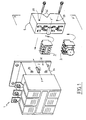
- a large-caliber contactor device 1, visible in FIG. 1, includes an internal electromagnet whose non-visible movable armature performs a certain stroke during its excitation and de-excitation.
- a lateral coupling member such as a pin or stud 2, being connected directly or not to this armature simultaneously performs a substantially rectilinear displacement of direction F which is exploited to cause the switching of associated auxiliary switches such as 3 which are , in the context of the present invention, generally intended to be combined with contactors of lower ratings.
- auxiliary switches whose stroke of the moving parts is substantially less than the previous one, could not be coupled to this pin without the putting into service of an appropriate adaptation device such as 4.
- auxiliary switches such as, for example, a timed switch 5
- auxiliary switches can also be combined with the contactor 1 thanks to this same adaptation device when their sizes and the strokes of their moving parts were also initially designed as part of an association with a contactor of lower rating.
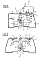
- the adaptation device 4 comprises a hollow envelope 6 in which are symmetrically pivoted concentrically about an axis YY ′ two levers 7, 8 substantially identical, but turned 180 °.
- the pivot can advantageously be materialized by a cylindrical rod coming from a part with the envelope.
- Each of the levers such as 7 comprises two perpendicular arms 9, 11 on either side of the common pivot 12, one of these 9 having a claw 15 respectively 16 for example in the form of a dovetail, while the other has a light 20 respectively 30.
- the latter takes the general form of an S, two end portions 17, 18 of which are connected by an intermediate central portion 19.
- This lever can oscillate by a value - alpha -, during a movement whose origin will be described later, and whose amplitude is such that the claw 15 can, for example, engage a certain amount in the internal volume 21 of the envelope for an extreme working position - T -, see FIG. 3, while it protrudes by another quantity - e - the surface 22 of the envelope for an opposite extreme position of rest - R - through an opening O, see Figure 1.
- the bottom 23 of the casing 6 has a notch 24 opposite which come the ends 25, 26 of the two levers, while a side wall 27 has two holes 28, 29 placed so precise with respect to the axis XX ′ and with respect to a central oblong opening 31 directed towards this axis.
- This oblong opening has a length - d - which is at least equal to the stroke that the coupling member 2 which can cross it can make when the envelope is precisely associated against the lateral face 32 of the contactor device. .
- the precision of this association which is obtained here thanks to two openings, threaded on this wall such as, for example, 33, 34, see FIG. 1, receiving fixing screws which circulate through the holes 28, 29, can also use other indexing means well known per se.
- the substantially straight stroke of the coupling member 2 is less than the total length of each light so that for each of the rest positions - R - and work - T - clearances - j1 - and - j2 - remain at both ends thereof for said active and inactive positions of the contactor.
- the angular displacements of the levers occur when the coupling member 2 circulates in the intermediate portion 19 inclined which connects the two non-aligned portions and substantially rectilinear ends.
- the coupling member When, during assembly, and therefore for the de-energized state of the contactor device, the coupling member must be introduced into the two lumens of the levers, these can be moved manually through the notch 24 so that s 'more easily establish an alignment allowing this introduction.
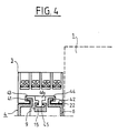
- the claw 15 engages around a suitable extension 45 belonging to a control rod 46 of the auxiliary switches, to communicate to the latter a determined movement - b - substantially constant.
- auxiliary switches I1, I2 must perform electrical locking functions, as is the case, for example, in direction-of-travel reversing arrangements for three-phase motors, where it is necessary to prevent overlapping of the periods d 'excitation of the two corresponding electromagnet coils, these two switches can not have simultaneous closing phases.
Abstract
Description
L'invention se rapporte à un dispositif d'adaptation placé entre l'un d'une multiplicité d'appareils contacteurs ayant des organes d'accouplement effectuant des courses distinctes dont il reçoit un premier mouvement et un boîtier d'interrupteurs auxiliaires qui est associé à ce dispositif pour en recevoir un second mouvement et qui présente des pièces de contact mobiles ayant une course de travail inférieure ou égale aux précédentes.The invention relates to an adaptation device placed between one of a multiplicity of contactor devices having coupling members performing separate strokes from which it receives a first movement and an auxiliary switch box which is associated to this device for receiving a second movement and which has movable contact parts having a working stroke less than or equal to the previous ones.
On a déjà proposé, par exemple dans la demande de brevet français No 87 09342 de la Demanderesse, un dispositif à came rotative dans lequel la rotation de celle-ci est transmise de façon non linéaire pour ne pas répercuter l'intégralité des mouvements que reçoit ce dispositif.We have already proposed, for example in French patent application No. 87 09342 of the Applicant, a rotary cam device in which the rotation of the latter is transmitted in a non-linear fashion so as not to reflect all the movements received these measures.
Ce dispositif convient lorsque, pour un encombrement déterminé de celui-ci, certaines proportions entre le mouvement d'entrée et le mouvement de sortie ne doivent pas être dépassées.This device is suitable when, for a given overall size thereof, certain proportions between the input movement and the output movement must not be exceeded.
Pour assurer des coupures convenables des arcs, les contacteurs sont appelés à exécuter des courses de travail qui croissent avec le calibre des courants passant par leurs interrupteurs principaux. Par contre, les courses des interrupteurs auxiliaires destinés à opérer des verrouillages électriques et à retransmettre des signalisations comparables sont similaires, puisque les charges qu'elles alimentent présentent toujours des caractéristiques voisines.To ensure proper breaking of the arcs, the contactors are called upon to execute working strokes which increase with the size of the currents passing through their main switches. On the other hand, the strokes of the auxiliary switches intended to operate electrical interlocks and to retransmit comparable signals are similar, since the loads which they supply always have similar characteristics.
Si l'on exclut la mise en oeuvre de dispositions particulières et coûteuses, ces interrupteurs auxiliaires ne pourront donc pas être directement accouplés aux pièces mobiles des appareils contacteurs auxquels on souhaite les associer.If the implementation of specific and costly provisions is excluded, these auxiliary switches cannot therefore be directly coupled to the moving parts of the contactor devices with which it is desired to associate them.
Si l'une des solutions possibles à ce problème peut consister en la fourniture d'une gamme d'appareils interrupteurs auxiliaires fabriqués sur mesure pour la gamme des contacteurs correspondants, un tel choix est de nature à augmenter inutilement les divers frais techniques de fabrication et de gestion découlant de la fabrication d'une multiplicité de moules, de la gestion de stocks de pièces multiples, etc... Par ailleurs, il implique également la publication en catalogue et la mise à disposition d'un ensemble d'appareils dont les formes extérieures voisines risquent de provoquer des confusions chez l'utilisateur.If one of the possible solutions to this problem may consist in the supply of a range of custom-made auxiliary switch devices for the range of corresponding contactors, such a choice is likely to unnecessarily increase the various technical manufacturing costs and management arising from the manufacture of a multiplicity of molds, the management of stocks of multiple parts, etc. Furthermore, it also involves the publication in catalog and the provision of a set of devices including neighboring external forms may cause confusion for the user.
L'invention se propose par suite d'écarter les inconvénients des moyens antérieurs et de mettre à la disposition des utilisateurs un dispositif d'adaptation qui permettra de monter sur tout appareil contacteur d'une gamme, des appareils interrupteurs auxiliaires présentant la taille et les courses de travail minimales requises pour une association de ceux-ci avec un appareil contacteur dont le calibre nominal est le plus bas dans la gamme.The invention therefore proposes to overcome the drawbacks of the prior means and to provide users with an adaptation device which will allow mounting on any contactor device of a range, auxiliary switch devices having the size and minimum working strokes required for a combination of these with a contactor device whose nominal rating is the lowest in the range.
Selon l'invention, le but visé est atteint grâce au fait que dans une enveloppe du dispositif d'adaptation, présentant des moyens d'indexation appropriés avec le corps du contacteur associé, se trouve pivoté un levier de transmission ayant, d'une part, un bras qui est pourvu d'une rainure en forme de S pour coopérer avec chacun des organes d'accouplement et présentant, d'autre part, une griffe d'accouplement externe apte à s'associer à un tiroir de commande appartenant à un appareil interrupteur auxiliaire, cette rainure comportant, entre deux portions d'extrémité non alignées, une portion intermédiaire de raccordement dont la longueur et l'orientation sont suffisantes pour communiquer au levier un basculement propre à conférer à la griffe un déplacement déterminé pour une fraction de la course de travail du contacteur ayant la course de travail la plus élevée de la gamme.According to the invention, the aim is achieved thanks to the fact that in an envelope of the adaptation device, having suitable indexing means with the body of the associated contactor, is pivoted a transmission lever having, on the one hand , an arm which is provided with a groove in S shape to cooperate with each of the coupling members and having, on the other hand, an external coupling claw adapted to be associated with a control slide belonging to an auxiliary switch, this groove comprising, between two portions of non-aligned ends, an intermediate connection portion of which the length and the orientation are sufficient to communicate to the lever a tilting capable of giving the claw a determined displacement for a fraction of the working stroke of the contactor having the working stroke the highest in the range.
Une telle disposition présente des avantages supplémentaires si la griffe d'association est accessible lorsque le dispositif intermédiaire est déjà associé au corps du contacteur, une rechange des appareils interrupteurs auxiliaires pouvant alors être aisément opérée sans qu'il soit nécessaire d'effectuer un démontage du dispositif d'adaptation.Such an arrangement has additional advantages if the association claw is accessible when the intermediate device is already associated with the body of the contactor, a replacement of the auxiliary switch devices can then be easily operated without the need to disassemble the adaptation device.
Par ailleurs, un élargissement des fonctions du dispositif d'adaptation peut être obtenu moyennant la mise en place de plusieurs leviers afin de disposer de deux griffes susceptibles d'actionner ainsi un couple d'appareils auxiliaires pouvant exécuter des fonctions distinctes comme, par exemple, la fermeture et l'ouverture instantanée ou retardée de contacts auxiliaires.Furthermore, a widening of the functions of the adaptation device can be obtained by means of the installation of several levers in order to have two claws capable of thus actuating a couple of auxiliary devices which can perform distinct functions such as, for example, closing and instantaneous or delayed opening of auxiliary contacts.
L'invention ainsi que d'autres mesures susceptibles d'en faciliter la mise en oeuvre, ou d'en accroître l'intérêt ou encore de l'adapter à des contacteurs de type particulier seront mieux comprises à la lecture de la description ci-dessous et à l'examen des figures annexées qui l'accompagnent en illustrant:
- A la figure 1: une vue en perspective éclatée d'un contacteur de gros calibre et du dispositif d'adaptation utilisé pour lui associer des boîtiers de contacts auxiliaires;
- A la figure 2: une vue en élévation coupée par un plan médian PP′ d'un dispositif d'adaptation destiné à l'association d'un seul boîtier de contacts auxiliaires et lorsque le contacteur est au repos;
- A la figure 3: une vue en élévation, coupée par le même plan, d'un dispositif d'adaptation propre à recevoir deux boîtiers de contacts auxiliaires ayant différentes fonctions;
- A la figure 4: une vue en coupe partielle par le plan QQ′ de la figure 2 d'un boîtier de contact auxiliaire accouplé à son levier de commande;
- A la figure 5: un diagramme établissant la relation entre les courses possibles d'armatures et celle que doit recevoir un contact mobile du boîtier d'interrupteurs auxiliaires.
- In FIG. 1: an exploded perspective view of a large gauge contactor and of the adaptation device used to associate it with auxiliary contact boxes;
- In Figure 2: an elevational view cut through a median plane PP 'of an adaptation device intended for the association of a single auxiliary contact box and when the contactor is at rest;
- In Figure 3: an elevational view, cut by the same plane, of a suitable adaptation device to receive two auxiliary contact boxes having different functions;
- In Figure 4: a partial sectional view through the plane QQ ′ of Figure 2 of an auxiliary contact box coupled to its control lever;
- In FIG. 5: a diagram establishing the relationship between the possible armature strokes and that which a movable contact must receive from the housing of auxiliary switches.
Un appareil contacteur de gros calibre 1, visible à la figure 1, comporte un électro-aimant interne dont l'armature mobile non visible effectue une certaine course lors de son excitation et de sa désexcitation. Un organe d'accouplement latéral tel qu'une goupille ou téton 2, se trouvant reliée directement ou non à cette armature effectue simultanément un déplacement sensiblement rectiligne de direction F qui est exploité pour provoquer la commutation d'interrupteurs auxiliaires associés tels que 3 qui sont, dans le cadre de la présente invention, généralement destinés à être combinés avec des contacteurs de calibres plus faibles. Ces interrupteurs auxiliaires, dont la course des pièces mobiles est sensiblement inférieure à la précédente, ne pourraient pas être accouplés à cette goupille sans la mise en service d'un dispositif d'adaptation approprié tel que 4.A large-caliber contactor device 1, visible in FIG. 1, includes an internal electromagnet whose non-visible movable armature performs a certain stroke during its excitation and de-excitation. A lateral coupling member such as a pin or
D'autres types d'interrupteurs auxiliaires, tels que, par exemple, un interrupteur temporisé 5, peuvent également faire l'objet d'une association avec le contacteur 1 grâce à ce même dispositif d'adaptation lorsque leurs tailles et les courses de leurs pièces mobiles ont été également initialement conçues dans le cadre d'une association avec un contacteur de calibre plus faible.Other types of auxiliary switches, such as, for example, a timed
Ainsi qu'on le voit mieux à la figure 2, le dispositif d'adaptation 4 comporte une enveloppe creuse 6 dans laquelle sont symétriquement pivotés de façon concentrique autour d'un axe YY′ deux leviers 7, 8 sensiblement identiques, mais retournés de 180°. Le pivot peut être avantageusement matérialisé par une tige cylindrique venant d'une pièce avec l'enveloppe.As can best be seen in FIG. 2, the
Compte tenu de la taille de l'appareil contacteur, deux leviers ont été ici mis en oeuvre dans une même enveloppe de dimensions adaptées alors qu'un seul levier pourrait être utilisé si cette taille présentait un volume plus réduit. Chacun des leviers tels que 7 comporte deux bras perpendiculaires 9, 11 de part et d'autre du pivot commun 12, l'un de ceux-ci 9 présentant une griffe 15 respectivement 16 par exemple en forme de queue d'aronde, tandis que l'autre comporte une lumière 20 respectivement 30. Cette dernière prend la forme générale d'un S dont deux portions d'extrémités 17, 18 sont reliées par une portion centrale intermédiaire 19.Given the size of the contactor device, two levers have been implemented here in the same envelope of suitable dimensions whereas a single lever could be used if this size had a smaller volume. Each of the levers such as 7 comprises two
Ce levier peut osciller d'une valeur ― alpha ―, au cours d'un mouvement dont l'origine sera décrite ultérieurement, et dont l'amplitude est telle que la griffe 15 peut, par exemple, s'engager d'une certaine quantité dans le volume interne 21 de l'enveloppe pour une position extrême de travail ― T ―, voir figure 3, alors qu'elle dépasse d'une autre quantité ― e ― la surface 22 de l'enveloppe pour une position extrême opposée de repos ― R ― à travers une ouverture O, voir figure 1. Le fond 23 de l'enveloppe 6 présente une encoche 24 en regard de laquelle viennent se présenter les extrémités 25, 26 des deux leviers, tandis qu'une paroi latérale 27 présente deux trous 28, 29 placés de façon précise par rapport à l'axe XX′ et par rapport à une ouverture oblongue centrale 31 dirigée vers cet axe. Cette ouverture oblongue présente une longueur ― d ― qui est au moins égale à la course que peut effectuer l'organe d'accouplement 2 qui vient la traverser lorsque l'enveloppe est associée de façon précise contre la face latérale 32 de l'appareil contacteur. La précision de cette association, qui est obtenue ici grâce à deux ouvertures, filetées de cette paroi telles que, par exemple, 33, 34, voir figure 1, recevant des vis de fixation qui circulent au travers des trous 28, 29, peut également faire appel à d'autres moyens d'indexation bien connus en soi.This lever can oscillate by a value - alpha -, during a movement whose origin will be described later, and whose amplitude is such that the
Au cours de leur pivotement, les diverses portions des lumières 20 et 30 se déplacent en regard de l'ouverture oblongue 31.During their pivoting, the various portions of the
Ces déplacements seront obtenus par suite des mouvements sensiblement rectilignes de l'organe d'accouplement 2 entre des positions actives et inactives, lorsque celui-ci aura été introduit dans les deux lumières après avoir traversé l'ouverture oblongue lorsque la paroi 27 de celle-ci est placée contre la face latérale 32. Ces pénétrations sont établies au moment où l'enveloppe 6 est associée avec l'appareil contacteur 1 à l'état de repos, voir figure 2.These displacements will be obtained as a result of substantially rectilinear movements of the
Ainsi qu'on le voit aux figures 2 et 3, la course sensiblement rectiligne de l'organe d'accouplement 2 est inférieure à la longueur totale que présente chaque lumière de sorte que pour chacune des positions de repos ― R ― et de travail ― T ― des jeux ― j1 ― et ― j2 ― subsistent aux deux extrémités de celles-ci pour lesdites positions actives et inactives du contacteur.As seen in Figures 2 and 3, the substantially straight stroke of the
Ainsi qu'on le constate sur ces deux figures, les déplacements angulaires des leviers se produisent lorsque l'organe d'accouplement 2 circule dans la portion intermédiaire 19 inclinée qui raccorde les deux portions non alignées et d'extrémités sensiblement rectilignes.As can be seen in these two figures, the angular displacements of the levers occur when the
En pratique, il est avantageux de donner à ces portions d'extrémité des directions rectilignes convergentes vers l'axe XX′ pour que les positions de repos et de travail des leviers soient bien déterminées même si l'amplitude de la course de l'organe de commande varie légèrement dans chacune des deux positions active et inactive du contacteur.In practice, it is advantageous to give these end portions rectilinear directions converging towards the axis XX ′ so that the rest and working positions of the levers are well determined even if the amplitude of the stroke of the member slightly varies in each of the two active and inactive contactor positions.
Lorsque, au montage, et donc pour l'état désexcité de l'appareil contacteur, l'organe d'accouplement doit être introduit dans les deux lumières des leviers, ceux-ci peuvent être déplacés manuellement à travers l'encoche 24 pour que s'établisse plus aisément un alignement permettant cette introduction.When, during assembly, and therefore for the de-energized state of the contactor device, the coupling member must be introduced into the two lumens of the levers, these can be moved manually through the
Une fois associées au contacteur, les différentes pièces mobiles se trouvent à l'état de repos représenté à la figure 1 et le dépassement des griffes 15, 16 permet la mise en place d'un bloc de contact auxiliaire temporisé ou non. Cette mise en place qui est guidée et assurée grâce à des saillies 41, 42 placées extérieurement sur la surface 22 pour s'engager dans des dégagements 43, 44 de formes adaptées, venant avec le boîtier des interrupteurs auxiliaires voir figure 4, s'effectue grâce à un mouvement de sens ― G ― sensiblement parallèle à la surface 22, voir figure 2.Once associated with the contactor, the various moving parts are in the rest state shown in FIG. 1 and the protrusion of the
Au cours de ce déplacement, la griffe 15 vient s'engager autour d'un prolongement adapté 45 appartenant à une tige de commande 46 des interrupteurs auxiliaires, pour communiquer à celle-ci un déplacement déterminé ― b ― sensiblement constant.During this movement, the
Si l'on se reporte au diagramme de la figure 5, où l'on a porté en abscisse les courses possibles des armatures de différents appareils contacteurs C1, C2, C3, C4 (ou de pièces de commande qui pourraient leur être directement reliées), et où l'on retrouve en ordonnées les déplacements angulaires des leviers de transmission, on constate que seule une fraction centrale AB de la courbe D est dévolue à l'actionnement des interrupteurs auxiliaires, de sorte que l'on se trouve à l'abri de variations importantes des tolérances de fabrication.If we refer to the diagram in FIG. 5, where we have plotted on the abscissa the possible strokes of the armatures of different contactor devices C1, C2, C3, C4 (or of control parts which could be directly to them connected), and where we find on the ordinate the angular displacements of the transmission levers, we note that only a central fraction AB of the curve D is devoted to the actuation of the auxiliary switches, so that we are at protected from significant variations in manufacturing tolerances.
Ces précautions sont importantes lorsque des interrupteurs auxiliaires I1, I2 doivent effectuer des fonctions de verrouillage électrique, comme le cas se présente par exemple dans les montages inverseurs du sens de marche de moteurs triphasés, où il est nécessaire d'empêcher un chevauchement des périodes d'excitation des deux bobines d'électro-aimant correspondantes, ces deux interrupteurs ne pouvant avoir de phases de fermeture simultanées.These precautions are important when auxiliary switches I1, I2 must perform electrical locking functions, as is the case, for example, in direction-of-travel reversing arrangements for three-phase motors, where it is necessary to prevent overlapping of the periods d 'excitation of the two corresponding electromagnet coils, these two switches can not have simultaneous closing phases.
Claims (6)
Applications Claiming Priority (2)
| Application Number | Priority Date | Filing Date | Title |
|---|---|---|---|
| FR8917013 | 1989-12-08 | ||
| FR898917013A FR2655769B1 (en) | 1989-12-08 | 1989-12-08 | ADAPTATION DEVICE FOR AUXILIARY CONTACTS BOX. |
Publications (2)
| Publication Number | Publication Date |
|---|---|
| EP0431994A1 true EP0431994A1 (en) | 1991-06-12 |
| EP0431994B1 EP0431994B1 (en) | 1994-07-27 |
Family
ID=9388832
Family Applications (1)
| Application Number | Title | Priority Date | Filing Date |
|---|---|---|---|
| EP90403126A Expired - Lifetime EP0431994B1 (en) | 1989-12-08 | 1990-11-06 | Adapter for auxiliary contact casing |
Country Status (7)
| Country | Link |
|---|---|
| US (1) | US5194705A (en) |
| EP (1) | EP0431994B1 (en) |
| JP (1) | JP3142588B2 (en) |
| DE (1) | DE69011058T2 (en) |
| ES (1) | ES2057485T3 (en) |
| FI (1) | FI98253C (en) |
| FR (1) | FR2655769B1 (en) |
Cited By (4)
| Publication number | Priority date | Publication date | Assignee | Title |
|---|---|---|---|---|
| FR2728383A1 (en) * | 1994-12-20 | 1996-06-21 | Legrand Sa | Circuit-breaker with curved fuseholder following arcuate trajectory |
| EP0780860A1 (en) * | 1995-12-20 | 1997-06-25 | Legrand | Auxiliary switch for circuit breaker and corresponding circuit breaker |
| WO2001013397A1 (en) * | 1999-08-12 | 2001-02-22 | Siemens Aktiengesellschaft | Electromagnetic switching device |
| WO2001069625A1 (en) * | 2000-03-17 | 2001-09-20 | Siemens Aktiengesellschaft | Electromagnetic switching device, in particular a contactor |
Families Citing this family (3)
| Publication number | Priority date | Publication date | Assignee | Title |
|---|---|---|---|---|
| ES2134153B1 (en) * | 1997-09-24 | 2000-05-01 | Power Controls Iberica Sl | AUXILIARY CONTACT DEVICE FOR CONNECTION TO POWER FACTOR CORRECTION CONTACTORS. |
| US6707688B2 (en) * | 2000-01-28 | 2004-03-16 | Hendry Mechanical Works | Electric apparatus with electric terminals and fused structures |
| DE202008016027U1 (en) * | 2008-12-04 | 2010-04-15 | Weidmüller Interface GmbH & Co. KG | Bayable housing |
Citations (4)
| Publication number | Priority date | Publication date | Assignee | Title |
|---|---|---|---|---|
| US3435389A (en) * | 1967-04-19 | 1969-03-25 | Allis Chalmers Mfg Co | Electromagnetic contactor having cam means for operating auxiliary switch |
| EP0086698A1 (en) * | 1982-02-12 | 1983-08-24 | Telemecanique | Small contactor provided with a removable sub-assembly of auxiliary switches |
| US4774484A (en) * | 1985-04-09 | 1988-09-27 | Square D Company | Auxiliary electrical contact for electromagnetic contactor |
| FR2617331A1 (en) * | 1987-06-26 | 1988-12-30 | Telemecanique Electrique | Contact unit usable on electromechanical apparatuses of various sizes |
Family Cites Families (2)
| Publication number | Priority date | Publication date | Assignee | Title |
|---|---|---|---|---|
| DE8713156U1 (en) * | 1987-09-30 | 1987-12-10 | La Telemecanique Electrique, Nanterre, Hauts-De-Seine, Fr | |
| FR2639144B1 (en) * | 1988-11-17 | 1993-05-28 | Telemecanique Electrique | LOCK MECHANISM FOR LIMIT SWITCH |
-
1989
- 1989-12-08 FR FR898917013A patent/FR2655769B1/en not_active Expired - Fee Related
-
1990
- 1990-11-06 ES ES90403126T patent/ES2057485T3/en not_active Expired - Lifetime
- 1990-11-06 DE DE69011058T patent/DE69011058T2/en not_active Expired - Fee Related
- 1990-11-06 EP EP90403126A patent/EP0431994B1/en not_active Expired - Lifetime
- 1990-11-29 US US07/619,549 patent/US5194705A/en not_active Expired - Lifetime
- 1990-12-03 FI FI905940A patent/FI98253C/en active IP Right Grant
- 1990-12-10 JP JP02415701A patent/JP3142588B2/en not_active Expired - Fee Related
Patent Citations (4)
| Publication number | Priority date | Publication date | Assignee | Title |
|---|---|---|---|---|
| US3435389A (en) * | 1967-04-19 | 1969-03-25 | Allis Chalmers Mfg Co | Electromagnetic contactor having cam means for operating auxiliary switch |
| EP0086698A1 (en) * | 1982-02-12 | 1983-08-24 | Telemecanique | Small contactor provided with a removable sub-assembly of auxiliary switches |
| US4774484A (en) * | 1985-04-09 | 1988-09-27 | Square D Company | Auxiliary electrical contact for electromagnetic contactor |
| FR2617331A1 (en) * | 1987-06-26 | 1988-12-30 | Telemecanique Electrique | Contact unit usable on electromechanical apparatuses of various sizes |
Cited By (6)
| Publication number | Priority date | Publication date | Assignee | Title |
|---|---|---|---|---|
| FR2728383A1 (en) * | 1994-12-20 | 1996-06-21 | Legrand Sa | Circuit-breaker with curved fuseholder following arcuate trajectory |
| EP0780860A1 (en) * | 1995-12-20 | 1997-06-25 | Legrand | Auxiliary switch for circuit breaker and corresponding circuit breaker |
| US5969587A (en) * | 1995-12-20 | 1999-10-19 | Legrand | Auxiliary switch for circuit-breaker and corresponding circuit-breaker |
| WO2001013397A1 (en) * | 1999-08-12 | 2001-02-22 | Siemens Aktiengesellschaft | Electromagnetic switching device |
| WO2001069625A1 (en) * | 2000-03-17 | 2001-09-20 | Siemens Aktiengesellschaft | Electromagnetic switching device, in particular a contactor |
| US6870450B2 (en) | 2000-03-17 | 2005-03-22 | Siemens Aktiengesellschaft | Electromagnetic switching device, in particular a contactor |
Also Published As
| Publication number | Publication date |
|---|---|
| FI905940A (en) | 1991-06-09 |
| DE69011058T2 (en) | 1994-11-17 |
| FI98253C (en) | 1997-05-12 |
| FI905940A0 (en) | 1990-12-03 |
| FR2655769B1 (en) | 1994-03-04 |
| ES2057485T3 (en) | 1994-10-16 |
| DE69011058D1 (en) | 1994-09-01 |
| FI98253B (en) | 1997-01-31 |
| JPH04126327A (en) | 1992-04-27 |
| JP3142588B2 (en) | 2001-03-07 |
| FR2655769A1 (en) | 1991-06-14 |
| US5194705A (en) | 1993-03-16 |
| EP0431994B1 (en) | 1994-07-27 |
Similar Documents
| Publication | Publication Date | Title |
|---|---|---|
| EP0431994B1 (en) | Adapter for auxiliary contact casing | |
| EP1652278B1 (en) | Three-position ground switch | |
| EP0174239A1 (en) | Polarised electromagnet presenting a symmetric disposition | |
| FR2878070A1 (en) | MECHANICAL CONTROL DEVICE FOR AN ELECTRICAL EQUIPMENT WITH THREE SWITCH POSITIONS HAVING A SELECTION LEVER COOPERATING WITH A CAME | |
| FR2598027A1 (en) | INVERTER CONTACTOR PROTECTS CURRENT OVERCURRENT CONTEXT | |
| CA1256927A (en) | Bi- or monostable operation polarized electromagnet | |
| EP1925008B1 (en) | Electric circuit switching device using at least two permanent magnets | |
| FR2892225A1 (en) | EAR DISCONNECT AND METHOD FOR MANUFACTURING SUCH EARTH DISCONNECT | |
| FR2789511A1 (en) | INSTALLATION COMPRISING AN ELECTRICAL SWITCHING APPARATUS AND A CABLE INTERLOCK | |
| CA1249622A (en) | Breaker apparatus with opening and closing through tele-control from associated circuits | |
| FR3010839A1 (en) | DEVICE FOR ELECTRICALLY CONNECTING AT LEAST ONE CONDUCTOR IN A TERMINAL BELONGING TO AN ELECTRICAL APPARATUS | |
| EP2575155B1 (en) | Medium-voltage electric distribution apparatus | |
| WO1992006483A1 (en) | Switching device comprising an auxiliary monostable switch coupled to a main switch | |
| FR2921767A1 (en) | Meter panel, has contact elements projected from lateral surface of case of cut-out device, where surface is turned towards plate through openings, and connection contacts arranged on plate's face that is turned away from cut-out device | |
| EP0156732B1 (en) | Electric knife, especially for cleaving oysters | |
| EP0948021B1 (en) | Multipolar differential switch | |
| EP1160816B1 (en) | Frame structure for vacuum tube of a power switch module | |
| EP2650582B1 (en) | Suspension arm for electrical appliance, electrical equipment for operating suite | |
| EP1998352B1 (en) | Contact device for an electrical appliance and auxiliary signalling comprising such a device | |
| EP1968160A2 (en) | Electrical appliance with prioritised automatic electric connections | |
| EP3644339B1 (en) | Apparatus for interrupting an electric current | |
| FR2617328A1 (en) | MECHANICAL AND ELECTRICAL CONDEMNATION DEVICE FOR CONTACTORS | |
| EP0073694B1 (en) | Switch device and its application to a commutator or programme switch | |
| FR2796488A1 (en) | DEVICE FOR ACTIVATING AND DEACTIVATING SWITCHING APPARATUSES IN BLOCK FORM | |
| WO2009118358A1 (en) | Electric cut-off device with augmented visibility |
Legal Events
| Date | Code | Title | Description |
|---|---|---|---|
| PUAI | Public reference made under article 153(3) epc to a published international application that has entered the european phase |
Free format text: ORIGINAL CODE: 0009012 |
|
| 17P | Request for examination filed |
Effective date: 19901113 |
|
| AK | Designated contracting states |
Kind code of ref document: A1 Designated state(s): DE ES GB IT SE |
|
| 17Q | First examination report despatched |
Effective date: 19931213 |
|
| GRAA | (expected) grant |
Free format text: ORIGINAL CODE: 0009210 |
|
| AK | Designated contracting states |
Kind code of ref document: B1 Designated state(s): DE ES GB IT SE |
|
| ITF | It: translation for a ep patent filed |
Owner name: ING. A. GIAMBROCONO & C. S.R.L. |
|
| REF | Corresponds to: |
Ref document number: 69011058 Country of ref document: DE Date of ref document: 19940901 |
|
| GBT | Gb: translation of ep patent filed (gb section 77(6)(a)/1977) |
Effective date: 19940818 |
|
| REG | Reference to a national code |
Ref country code: ES Ref legal event code: FG2A Ref document number: 2057485 Country of ref document: ES Kind code of ref document: T3 |
|
| EAL | Se: european patent in force in sweden |
Ref document number: 90403126.7 |
|
| PLBE | No opposition filed within time limit |
Free format text: ORIGINAL CODE: 0009261 |
|
| STAA | Information on the status of an ep patent application or granted ep patent |
Free format text: STATUS: NO OPPOSITION FILED WITHIN TIME LIMIT |
|
| 26N | No opposition filed | ||
| REG | Reference to a national code |
Ref country code: GB Ref legal event code: IF02 |
|
| REG | Reference to a national code |
Ref country code: GB Ref legal event code: 732E |
|
| PGFP | Annual fee paid to national office [announced via postgrant information from national office to epo] |
Ref country code: DE Payment date: 20081013 Year of fee payment: 19 |
|
| PGFP | Annual fee paid to national office [announced via postgrant information from national office to epo] |
Ref country code: ES Payment date: 20081120 Year of fee payment: 19 |
|
| PGFP | Annual fee paid to national office [announced via postgrant information from national office to epo] |
Ref country code: SE Payment date: 20081028 Year of fee payment: 19 Ref country code: IT Payment date: 20081114 Year of fee payment: 19 |
|
| PGFP | Annual fee paid to national office [announced via postgrant information from national office to epo] |
Ref country code: GB Payment date: 20081107 Year of fee payment: 19 |
|
| EUG | Se: european patent has lapsed | ||
| GBPC | Gb: european patent ceased through non-payment of renewal fee |
Effective date: 20091106 |
|
| PG25 | Lapsed in a contracting state [announced via postgrant information from national office to epo] |
Ref country code: DE Free format text: LAPSE BECAUSE OF NON-PAYMENT OF DUE FEES Effective date: 20100601 |
|
| PG25 | Lapsed in a contracting state [announced via postgrant information from national office to epo] |
Ref country code: GB Free format text: LAPSE BECAUSE OF NON-PAYMENT OF DUE FEES Effective date: 20091106 |
|
| PG25 | Lapsed in a contracting state [announced via postgrant information from national office to epo] |
Ref country code: IT Free format text: LAPSE BECAUSE OF NON-PAYMENT OF DUE FEES Effective date: 20091106 |
|
| REG | Reference to a national code |
Ref country code: ES Ref legal event code: FD2A Effective date: 20110408 |
|
| PG25 | Lapsed in a contracting state [announced via postgrant information from national office to epo] |
Ref country code: SE Free format text: LAPSE BECAUSE OF NON-PAYMENT OF DUE FEES Effective date: 20091107 |
|
| PG25 | Lapsed in a contracting state [announced via postgrant information from national office to epo] |
Ref country code: ES Free format text: LAPSE BECAUSE OF NON-PAYMENT OF DUE FEES Effective date: 20110328 |
|
| PG25 | Lapsed in a contracting state [announced via postgrant information from national office to epo] |
Ref country code: ES Free format text: LAPSE BECAUSE OF NON-PAYMENT OF DUE FEES Effective date: 20091107 |