EP0431994A1 - Anpassungseinrichtung für Nebenkontaktgehäuse - Google Patents
Anpassungseinrichtung für Nebenkontaktgehäuse Download PDFInfo
- Publication number
- EP0431994A1 EP0431994A1 EP90403126A EP90403126A EP0431994A1 EP 0431994 A1 EP0431994 A1 EP 0431994A1 EP 90403126 A EP90403126 A EP 90403126A EP 90403126 A EP90403126 A EP 90403126A EP 0431994 A1 EP0431994 A1 EP 0431994A1
- Authority
- EP
- European Patent Office
- Prior art keywords
- contactor
- adaptation device
- groove
- casing
- claw
- Prior art date
- Legal status (The legal status is an assumption and is not a legal conclusion. Google has not performed a legal analysis and makes no representation as to the accuracy of the status listed.)
- Granted
Links
Images

Classifications
-
- H—ELECTRICITY
- H01—ELECTRIC ELEMENTS
- H01H—ELECTRIC SWITCHES; RELAYS; SELECTORS; EMERGENCY PROTECTIVE DEVICES
- H01H50/00—Details of electromagnetic relays
- H01H50/54—Contact arrangements
- H01H50/541—Auxiliary contact devices
- H01H50/545—Self-contained, easily replaceable microswitches
-
- H—ELECTRICITY
- H01—ELECTRIC ELEMENTS
- H01H—ELECTRIC SWITCHES; RELAYS; SELECTORS; EMERGENCY PROTECTIVE DEVICES
- H01H15/00—Switches having rectilinearly-movable operating part or parts adapted for actuation in opposite directions, e.g. slide switch
- H01H15/02—Details
- H01H15/06—Movable parts; Contacts mounted thereon
- H01H15/10—Operating parts
- H01H15/102—Operating parts comprising cam devices
Definitions
- the invention relates to an adaptation device placed between one of a multiplicity of contactor devices having coupling members performing separate strokes from which it receives a first movement and an auxiliary switch box which is associated to this device for receiving a second movement and which has movable contact parts having a working stroke less than or equal to the previous ones.
- This device is suitable when, for a given overall size thereof, certain proportions between the input movement and the output movement must not be exceeded.
- the contactors are called upon to execute working strokes which increase with the size of the currents passing through their main switches.
- the strokes of the auxiliary switches intended to operate electrical interlocks and to retransmit comparable signals are similar, since the loads which they supply always have similar characteristics.
- one of the possible solutions to this problem may consist in the supply of a range of custom-made auxiliary switch devices for the range of corresponding contactors, such a choice is likely to unnecessarily increase the various technical manufacturing costs and management arising from the manufacture of a multiplicity of molds, the management of stocks of multiple parts, etc. Furthermore, it also involves the publication in catalog and the provision of a set of devices including neighboring external forms may cause confusion for the user.
- the invention therefore proposes to overcome the drawbacks of the prior means and to provide users with an adaptation device which will allow mounting on any contactor device of a range, auxiliary switch devices having the size and minimum working strokes required for a combination of these with a contactor device whose nominal rating is the lowest in the range.
- the aim is achieved thanks to the fact that in an envelope of the adaptation device, having suitable indexing means with the body of the associated contactor, is pivoted a transmission lever having, on the one hand , an arm which is provided with a groove in S shape to cooperate with each of the coupling members and having, on the other hand, an external coupling claw adapted to be associated with a control slide belonging to an auxiliary switch, this groove comprising, between two portions of non-aligned ends, an intermediate connection portion of which the length and the orientation are sufficient to communicate to the lever a tilting capable of giving the claw a determined displacement for a fraction of the working stroke of the contactor having the working stroke the highest in the range.
- association claw is accessible when the intermediate device is already associated with the body of the contactor, a replacement of the auxiliary switch devices can then be easily operated without the need to disassemble the adaptation device.
- a widening of the functions of the adaptation device can be obtained by means of the installation of several levers in order to have two claws capable of thus actuating a couple of auxiliary devices which can perform distinct functions such as, for example, closing and instantaneous or delayed opening of auxiliary contacts.
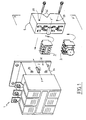
- a large-caliber contactor device 1, visible in FIG. 1, includes an internal electromagnet whose non-visible movable armature performs a certain stroke during its excitation and de-excitation.
- a lateral coupling member such as a pin or stud 2, being connected directly or not to this armature simultaneously performs a substantially rectilinear displacement of direction F which is exploited to cause the switching of associated auxiliary switches such as 3 which are , in the context of the present invention, generally intended to be combined with contactors of lower ratings.
- auxiliary switches whose stroke of the moving parts is substantially less than the previous one, could not be coupled to this pin without the putting into service of an appropriate adaptation device such as 4.
- auxiliary switches such as, for example, a timed switch 5
- auxiliary switches can also be combined with the contactor 1 thanks to this same adaptation device when their sizes and the strokes of their moving parts were also initially designed as part of an association with a contactor of lower rating.
- the adaptation device 4 comprises a hollow envelope 6 in which are symmetrically pivoted concentrically about an axis YY ′ two levers 7, 8 substantially identical, but turned 180 °.
- the pivot can advantageously be materialized by a cylindrical rod coming from a part with the envelope.
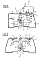
- Each of the levers such as 7 comprises two perpendicular arms 9, 11 on either side of the common pivot 12, one of these 9 having a claw 15 respectively 16 for example in the form of a dovetail, while the other has a light 20 respectively 30.
- the latter takes the general form of an S, two end portions 17, 18 of which are connected by an intermediate central portion 19.
- This lever can oscillate by a value - alpha -, during a movement whose origin will be described later, and whose amplitude is such that the claw 15 can, for example, engage a certain amount in the internal volume 21 of the envelope for an extreme working position - T -, see FIG. 3, while it protrudes by another quantity - e - the surface 22 of the envelope for an opposite extreme position of rest - R - through an opening O, see Figure 1.
- the bottom 23 of the casing 6 has a notch 24 opposite which come the ends 25, 26 of the two levers, while a side wall 27 has two holes 28, 29 placed so precise with respect to the axis XX ′ and with respect to a central oblong opening 31 directed towards this axis.
- This oblong opening has a length - d - which is at least equal to the stroke that the coupling member 2 which can cross it can make when the envelope is precisely associated against the lateral face 32 of the contactor device. .
- the precision of this association which is obtained here thanks to two openings, threaded on this wall such as, for example, 33, 34, see FIG. 1, receiving fixing screws which circulate through the holes 28, 29, can also use other indexing means well known per se.
- the substantially straight stroke of the coupling member 2 is less than the total length of each light so that for each of the rest positions - R - and work - T - clearances - j1 - and - j2 - remain at both ends thereof for said active and inactive positions of the contactor.
- the angular displacements of the levers occur when the coupling member 2 circulates in the intermediate portion 19 inclined which connects the two non-aligned portions and substantially rectilinear ends.
- the coupling member When, during assembly, and therefore for the de-energized state of the contactor device, the coupling member must be introduced into the two lumens of the levers, these can be moved manually through the notch 24 so that s 'more easily establish an alignment allowing this introduction.
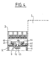
- the claw 15 engages around a suitable extension 45 belonging to a control rod 46 of the auxiliary switches, to communicate to the latter a determined movement - b - substantially constant.
- auxiliary switches I1, I2 must perform electrical locking functions, as is the case, for example, in direction-of-travel reversing arrangements for three-phase motors, where it is necessary to prevent overlapping of the periods d 'excitation of the two corresponding electromagnet coils, these two switches can not have simultaneous closing phases.
Landscapes
- Physics & Mathematics (AREA)
- Electromagnetism (AREA)
- Switch Cases, Indication, And Locking (AREA)
- Rotary Switch, Piano Key Switch, And Lever Switch (AREA)
- Mechanisms For Operating Contacts (AREA)
- Push-Button Switches (AREA)
- Driving Mechanisms And Operating Circuits Of Arc-Extinguishing High-Tension Switches (AREA)
Applications Claiming Priority (2)
| Application Number | Priority Date | Filing Date | Title |
|---|---|---|---|
| FR8917013 | 1989-12-08 | ||
| FR898917013A FR2655769B1 (fr) | 1989-12-08 | 1989-12-08 | Dispositif d'adaptation pour boitier de contacts auxiliaires. |
Publications (2)
| Publication Number | Publication Date |
|---|---|
| EP0431994A1 true EP0431994A1 (de) | 1991-06-12 |
| EP0431994B1 EP0431994B1 (de) | 1994-07-27 |
Family
ID=9388832
Family Applications (1)
| Application Number | Title | Priority Date | Filing Date |
|---|---|---|---|
| EP90403126A Expired - Lifetime EP0431994B1 (de) | 1989-12-08 | 1990-11-06 | Anpassungseinrichtung für Nebenkontaktgehäuse |
Country Status (7)
| Country | Link |
|---|---|
| US (1) | US5194705A (de) |
| EP (1) | EP0431994B1 (de) |
| JP (1) | JP3142588B2 (de) |
| DE (1) | DE69011058T2 (de) |
| ES (1) | ES2057485T3 (de) |
| FI (1) | FI98253C (de) |
| FR (1) | FR2655769B1 (de) |
Cited By (4)
| Publication number | Priority date | Publication date | Assignee | Title |
|---|---|---|---|---|
| FR2728383A1 (fr) * | 1994-12-20 | 1996-06-21 | Legrand Sa | Interrupteur auxiliaire pour coupe-circuit, et coupe-circuit correspondant |
| EP0780860A1 (de) * | 1995-12-20 | 1997-06-25 | Legrand | Hilfsschalter für Ausschalter und entsprechender Ausschalter |
| WO2001013397A1 (de) * | 1999-08-12 | 2001-02-22 | Siemens Aktiengesellschaft | Elektromagnetisches schaltgerät |
| WO2001069625A1 (de) * | 2000-03-17 | 2001-09-20 | Siemens Aktiengesellschaft | Elektromagnetisches schaltgerät, insbesondere schütz |
Families Citing this family (3)
| Publication number | Priority date | Publication date | Assignee | Title |
|---|---|---|---|---|
| ES2134153B1 (es) * | 1997-09-24 | 2000-05-01 | Power Controls Iberica Sl | Dispositivo de contactos auxiliares para conexion a contactores de correccion del factor de potencia. |
| US6707688B2 (en) * | 2000-01-28 | 2004-03-16 | Hendry Mechanical Works | Electric apparatus with electric terminals and fused structures |
| DE202008016027U1 (de) * | 2008-12-04 | 2010-04-15 | Weidmüller Interface GmbH & Co. KG | Anreihbares Gehäuse |
Citations (4)
| Publication number | Priority date | Publication date | Assignee | Title |
|---|---|---|---|---|
| US3435389A (en) * | 1967-04-19 | 1969-03-25 | Allis Chalmers Mfg Co | Electromagnetic contactor having cam means for operating auxiliary switch |
| EP0086698A1 (de) * | 1982-02-12 | 1983-08-24 | Telemecanique | Kleinschütz mit entfernbarer Hilfsschalterbaugruppe |
| US4774484A (en) * | 1985-04-09 | 1988-09-27 | Square D Company | Auxiliary electrical contact for electromagnetic contactor |
| FR2617331A1 (fr) * | 1987-06-26 | 1988-12-30 | Telemecanique Electrique | Bloc de contact auxiliaire utilisable sur des appareils electromecaniques de tailles differentes |
Family Cites Families (2)
| Publication number | Priority date | Publication date | Assignee | Title |
|---|---|---|---|---|
| DE8713156U1 (de) * | 1987-09-30 | 1987-12-10 | La Telemecanique Electrique, Nanterre, Hauts-De-Seine, Fr | |
| FR2639144B1 (fr) * | 1988-11-17 | 1993-05-28 | Telemecanique Electrique | Mecanisme a serrure pour contacteur-limiteur |
-
1989
- 1989-12-08 FR FR898917013A patent/FR2655769B1/fr not_active Expired - Fee Related
-
1990
- 1990-11-06 ES ES90403126T patent/ES2057485T3/es not_active Expired - Lifetime
- 1990-11-06 DE DE69011058T patent/DE69011058T2/de not_active Expired - Fee Related
- 1990-11-06 EP EP90403126A patent/EP0431994B1/de not_active Expired - Lifetime
- 1990-11-29 US US07/619,549 patent/US5194705A/en not_active Expired - Lifetime
- 1990-12-03 FI FI905940A patent/FI98253C/fi active IP Right Grant
- 1990-12-10 JP JP02415701A patent/JP3142588B2/ja not_active Expired - Fee Related
Patent Citations (4)
| Publication number | Priority date | Publication date | Assignee | Title |
|---|---|---|---|---|
| US3435389A (en) * | 1967-04-19 | 1969-03-25 | Allis Chalmers Mfg Co | Electromagnetic contactor having cam means for operating auxiliary switch |
| EP0086698A1 (de) * | 1982-02-12 | 1983-08-24 | Telemecanique | Kleinschütz mit entfernbarer Hilfsschalterbaugruppe |
| US4774484A (en) * | 1985-04-09 | 1988-09-27 | Square D Company | Auxiliary electrical contact for electromagnetic contactor |
| FR2617331A1 (fr) * | 1987-06-26 | 1988-12-30 | Telemecanique Electrique | Bloc de contact auxiliaire utilisable sur des appareils electromecaniques de tailles differentes |
Cited By (6)
| Publication number | Priority date | Publication date | Assignee | Title |
|---|---|---|---|---|
| FR2728383A1 (fr) * | 1994-12-20 | 1996-06-21 | Legrand Sa | Interrupteur auxiliaire pour coupe-circuit, et coupe-circuit correspondant |
| EP0780860A1 (de) * | 1995-12-20 | 1997-06-25 | Legrand | Hilfsschalter für Ausschalter und entsprechender Ausschalter |
| US5969587A (en) * | 1995-12-20 | 1999-10-19 | Legrand | Auxiliary switch for circuit-breaker and corresponding circuit-breaker |
| WO2001013397A1 (de) * | 1999-08-12 | 2001-02-22 | Siemens Aktiengesellschaft | Elektromagnetisches schaltgerät |
| WO2001069625A1 (de) * | 2000-03-17 | 2001-09-20 | Siemens Aktiengesellschaft | Elektromagnetisches schaltgerät, insbesondere schütz |
| US6870450B2 (en) | 2000-03-17 | 2005-03-22 | Siemens Aktiengesellschaft | Electromagnetic switching device, in particular a contactor |
Also Published As
| Publication number | Publication date |
|---|---|
| FI98253C (fi) | 1997-05-12 |
| ES2057485T3 (es) | 1994-10-16 |
| EP0431994B1 (de) | 1994-07-27 |
| FI98253B (fi) | 1997-01-31 |
| JPH04126327A (ja) | 1992-04-27 |
| JP3142588B2 (ja) | 2001-03-07 |
| FI905940A0 (fi) | 1990-12-03 |
| DE69011058D1 (de) | 1994-09-01 |
| DE69011058T2 (de) | 1994-11-17 |
| FR2655769A1 (fr) | 1991-06-14 |
| FI905940A (fi) | 1991-06-09 |
| FR2655769B1 (fr) | 1994-03-04 |
| US5194705A (en) | 1993-03-16 |
Similar Documents
| Publication | Publication Date | Title |
|---|---|---|
| EP0431994B1 (de) | Anpassungseinrichtung für Nebenkontaktgehäuse | |
| FR2644929A1 (fr) | Contacteur electromagnetique | |
| EP1652278B1 (de) | Masseschalter mit drei stellungen | |
| EP0174239A1 (de) | Polarisierter Elektromagnet in symmetrischer Ausführung | |
| FR2878070A1 (fr) | Dispositif de commande mecanique pour un appareillage electrique a trois positions de commutation ayant un levier de selection cooperant avec une came | |
| FR2598027A1 (fr) | Appareil contacteur inverseur protege conte les surintensites de courant | |
| EP1925008B1 (de) | Einrichtung zum umschalten eines elektrischen schaltkreises unter verwendung von mindestens zwei permanentmagneten | |
| FR2789511A1 (fr) | Installation comportant un appareillage electrique de coupure et un interverrouillage a cable | |
| CA1249622A (fr) | Appareil disjoncteur a ouverture et fermeture telecommandees de ses circuits | |
| FR3010839A1 (fr) | Dispositif de raccordement electrique d'au moins un conducteur dans une borne appartenant a un appareil electrique | |
| EP2575155B1 (de) | Gerät zur verteilung von strom mittlerer spannung | |
| WO1992006483A1 (fr) | Dispositif de commutation comprenant un interrupteur auxiliaire a fonctionnement monostable couple a un interrupteur principal | |
| EP0156732B1 (de) | Elektrisches Messer, insbesondere zum Öffnen von Austern | |
| EP0948021B1 (de) | Multipoläre differenzial Schalter | |
| EP1160816B1 (de) | Rahmenstruktur für die Vakuumröhre eines Leistungsschaltermoduls | |
| EP2650582B1 (de) | Schwingarm für Elektrogerät, elektrische Ausstattung für Operationstrakt | |
| EP1998352B1 (de) | Kontaktvorrichtung für ein elektrisches Gerät und Signalisierungshilfsgerät, das eine solche Vorrichtung umfasst | |
| FR2577712A1 (fr) | Interrupteur de protection | |
| EP1968160A2 (de) | Elektrischer Apparat mit automatischen elektrischen Prioritätsanschlüssen | |
| EP3644339B1 (de) | Gerät zur unterbrechung eines elektrischen stroms | |
| FR2665030A1 (fr) | Dispositif de commutation recevant un certain nombre de commutateurs dans un boitier. | |
| EP0073694B1 (de) | Schalteinrichtung und deren Anwendung in einem Wechselschalter oder Programmschalter | |
| FR2796488A1 (fr) | Dispositif pour activer et desactiver des appareils de commutation agences sous forme de bloc | |
| WO2009118358A1 (fr) | Dispositif de coupure électrique avec visibilité augmentée | |
| FR2771848A1 (fr) | Interrupteur electrique pouvant realiser plusieurs fonctions , par exemple les fonctions poussoir, va et vient,avec les memes pieces de base |
Legal Events
| Date | Code | Title | Description |
|---|---|---|---|
| PUAI | Public reference made under article 153(3) epc to a published international application that has entered the european phase |
Free format text: ORIGINAL CODE: 0009012 |
|
| 17P | Request for examination filed |
Effective date: 19901113 |
|
| AK | Designated contracting states |
Kind code of ref document: A1 Designated state(s): DE ES GB IT SE |
|
| 17Q | First examination report despatched |
Effective date: 19931213 |
|
| GRAA | (expected) grant |
Free format text: ORIGINAL CODE: 0009210 |
|
| AK | Designated contracting states |
Kind code of ref document: B1 Designated state(s): DE ES GB IT SE |
|
| ITF | It: translation for a ep patent filed |
Owner name: ING. A. GIAMBROCONO & C. S.R.L. |
|
| REF | Corresponds to: |
Ref document number: 69011058 Country of ref document: DE Date of ref document: 19940901 |
|
| GBT | Gb: translation of ep patent filed (gb section 77(6)(a)/1977) |
Effective date: 19940818 |
|
| REG | Reference to a national code |
Ref country code: ES Ref legal event code: FG2A Ref document number: 2057485 Country of ref document: ES Kind code of ref document: T3 |
|
| EAL | Se: european patent in force in sweden |
Ref document number: 90403126.7 |
|
| PLBE | No opposition filed within time limit |
Free format text: ORIGINAL CODE: 0009261 |
|
| STAA | Information on the status of an ep patent application or granted ep patent |
Free format text: STATUS: NO OPPOSITION FILED WITHIN TIME LIMIT |
|
| 26N | No opposition filed | ||
| REG | Reference to a national code |
Ref country code: GB Ref legal event code: IF02 |
|
| REG | Reference to a national code |
Ref country code: GB Ref legal event code: 732E |
|
| PGFP | Annual fee paid to national office [announced via postgrant information from national office to epo] |
Ref country code: DE Payment date: 20081013 Year of fee payment: 19 |
|
| PGFP | Annual fee paid to national office [announced via postgrant information from national office to epo] |
Ref country code: ES Payment date: 20081120 Year of fee payment: 19 |
|
| PGFP | Annual fee paid to national office [announced via postgrant information from national office to epo] |
Ref country code: SE Payment date: 20081028 Year of fee payment: 19 Ref country code: IT Payment date: 20081114 Year of fee payment: 19 |
|
| PGFP | Annual fee paid to national office [announced via postgrant information from national office to epo] |
Ref country code: GB Payment date: 20081107 Year of fee payment: 19 |
|
| EUG | Se: european patent has lapsed | ||
| GBPC | Gb: european patent ceased through non-payment of renewal fee |
Effective date: 20091106 |
|
| PG25 | Lapsed in a contracting state [announced via postgrant information from national office to epo] |
Ref country code: DE Free format text: LAPSE BECAUSE OF NON-PAYMENT OF DUE FEES Effective date: 20100601 |
|
| PG25 | Lapsed in a contracting state [announced via postgrant information from national office to epo] |
Ref country code: GB Free format text: LAPSE BECAUSE OF NON-PAYMENT OF DUE FEES Effective date: 20091106 |
|
| PG25 | Lapsed in a contracting state [announced via postgrant information from national office to epo] |
Ref country code: IT Free format text: LAPSE BECAUSE OF NON-PAYMENT OF DUE FEES Effective date: 20091106 |
|
| REG | Reference to a national code |
Ref country code: ES Ref legal event code: FD2A Effective date: 20110408 |
|
| PG25 | Lapsed in a contracting state [announced via postgrant information from national office to epo] |
Ref country code: SE Free format text: LAPSE BECAUSE OF NON-PAYMENT OF DUE FEES Effective date: 20091107 |
|
| PG25 | Lapsed in a contracting state [announced via postgrant information from national office to epo] |
Ref country code: ES Free format text: LAPSE BECAUSE OF NON-PAYMENT OF DUE FEES Effective date: 20110328 |
|
| PG25 | Lapsed in a contracting state [announced via postgrant information from national office to epo] |
Ref country code: ES Free format text: LAPSE BECAUSE OF NON-PAYMENT OF DUE FEES Effective date: 20091107 |