EP0431802A2 - Montage für Lampe - Google Patents
Montage für Lampe Download PDFInfo
- Publication number
- EP0431802A2 EP0431802A2 EP90312695A EP90312695A EP0431802A2 EP 0431802 A2 EP0431802 A2 EP 0431802A2 EP 90312695 A EP90312695 A EP 90312695A EP 90312695 A EP90312695 A EP 90312695A EP 0431802 A2 EP0431802 A2 EP 0431802A2
- Authority
- EP
- European Patent Office
- Prior art keywords
- socket
- adjusting screw
- lamp assembly
- support
- reflector body
- Prior art date
- Legal status (The legal status is an assumption and is not a legal conclusion. Google has not performed a legal analysis and makes no representation as to the accuracy of the status listed.)
- Withdrawn
Links
Images
Classifications
-
- B—PERFORMING OPERATIONS; TRANSPORTING
- B60—VEHICLES IN GENERAL
- B60Q—ARRANGEMENT OF SIGNALLING OR LIGHTING DEVICES, THE MOUNTING OR SUPPORTING THEREOF OR CIRCUITS THEREFOR, FOR VEHICLES IN GENERAL
- B60Q1/00—Arrangement of optical signalling or lighting devices, the mounting or supporting thereof or circuits therefor
- B60Q1/02—Arrangement of optical signalling or lighting devices, the mounting or supporting thereof or circuits therefor the devices being primarily intended to illuminate the way ahead or to illuminate other areas of way or environments
- B60Q1/04—Arrangement of optical signalling or lighting devices, the mounting or supporting thereof or circuits therefor the devices being primarily intended to illuminate the way ahead or to illuminate other areas of way or environments the devices being headlights
- B60Q1/06—Arrangement of optical signalling or lighting devices, the mounting or supporting thereof or circuits therefor the devices being primarily intended to illuminate the way ahead or to illuminate other areas of way or environments the devices being headlights adjustable, e.g. remotely-controlled from inside vehicle
- B60Q1/068—Arrangement of optical signalling or lighting devices, the mounting or supporting thereof or circuits therefor the devices being primarily intended to illuminate the way ahead or to illuminate other areas of way or environments the devices being headlights adjustable, e.g. remotely-controlled from inside vehicle by mechanical means
- B60Q1/0683—Adjustable by rotation of a screw
-
- F—MECHANICAL ENGINEERING; LIGHTING; HEATING; WEAPONS; BLASTING
- F21—LIGHTING
- F21S—NON-PORTABLE LIGHTING DEVICES; SYSTEMS THEREOF; VEHICLE LIGHTING DEVICES SPECIALLY ADAPTED FOR VEHICLE EXTERIORS
- F21S41/00—Illuminating devices specially adapted for vehicle exteriors, e.g. headlamps
- F21S41/60—Illuminating devices specially adapted for vehicle exteriors, e.g. headlamps characterised by a variable light distribution
- F21S41/67—Illuminating devices specially adapted for vehicle exteriors, e.g. headlamps characterised by a variable light distribution by acting on reflectors
- F21S41/675—Illuminating devices specially adapted for vehicle exteriors, e.g. headlamps characterised by a variable light distribution by acting on reflectors by moving reflectors
Definitions
- This invention relates to a lamp assembly of the type in which a reflector body is adjustably mounted relative to a support by mounting means including a socket carried by the reflector body and an adjusting screw rotatably mounted on the support, the adjusting screw having a part-spherical end which is a snap fit in the socket.
- a lamp assembly having mounting means of this type is commonly used in motor vehicle lamp assemblies, particularly motor vehicle headlamp assemblies, where two such adjusting screws and sockets are provided for enabling the reflector body to be tilted independently about horizontal and vertical axes for headlamp beam adjusting purposes. It is a disadvantage of previously proposed lamb assemblies of this type that, when the adjusting screw is moved beyond its design limit, the part-spherical end can become detached from its socket.
- a lamp assembly comprising a support, a lamp reflector body, and mounting means adjustably mounting the reflector body on the support, said mounting means including a socket carried by the reflector body and an adjusting screw rotatably mounted on the support, said adjusting screw having a part-spherical end which is a snap fit in the socket, characterized in that means are provided for limiting opening of the socket, said limiting means being adapted to be in engagement with said socket when the adjusting screw has moved beyond a predetermined position in a direction tending to separate the part-spherical end from the socket.
- the limiting means includes a tapered internal surface against which a tapered external surface of the socket is adapted to engage when the adjusting screw is in said predetermined position.
- the limiting means may be provided by a member which is slidably mounted on the adjusting screw and which is in abutment with the support when the adjusting screw is in its predetermined position.
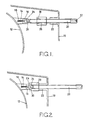
- Fig. 1 is a perspective view of part of a lamp assembly according to the present invention showing an adjusting screw in a position in which it has not reached a predetermined limit position, and
- Fig. 2 is a view similar to Fig. 1 showing the adjusting screw in its predetermined limit position.
- the lamp assembly illustrated in Figs. 1 and 2 is a motor vehicle headlamp assembly comprising a support 10 in the form of a synthetic resin housing which is fixedly mounted in a manner known per se on the motor vehicle.
- a dished reflector body 12 is disposed within the housing 10.
- the reflector body 12 is conveniently formed of an injection moulded thermosetting plastics material with three integral mounting lugs 14 (only one shown) extending rearwardly therefrom.
- Each mounting lug 14 has a resilient, synthetic resin socket 16 secured thereto by means of a screw 18.
- the three sockets 16 form part of a three-point mounting system whereby the reflector body 12 is adjustably mounted in the housing 10 for independent pivotal movement about horizontal and vertical axes for beam aiming purposes.
- Such a three-point mounting system is per se known.
- One of the mounting points is provided by a post (not shown) which is fixedly secured to the housing 10 and which has a part-spherical end which is snap fitted into the respective socket.
- the other two mounting points (of which one only is illustrated) enable tilting of the reflector body 12 about the respective horizontal and vertical axes.
- an externally screw threaded adjusting rod 20 extends through the housing 10 and engages in an internally screw threaded sleeve 22 integrally formed within the housing 10.
- An inner end of the adjusting screw 20 is provided with a part-spherical end 24 which is snap fitted into the socket 16, the latter being partly split to permit outward deformation of the wall of the socket during snap-fitting of the part-spherical end 24 therein.
- the outer surface 26 of the socket 16 is frusto-conically tapered.
- the lamp assembly further comprises limiting means in the form of a sleeve 28 having a frusto-conically tapered internal surface corresponding to the tapered outer surface 26 of the socket 16.
- the surfaces 26 and 30 face each other.
- the sleeve 28 is slidably mounted on the adjusting screw 20.
- the outer end portion 32 of each adjusting screw 20 has a hexagonal form and is also slotted to enable the adjusting screw 20 to be rotated either by means of a spanner or by means of a screwdriver.
- the adjusting screw 20 will normally be in the position illustrated in Fig. 1. However, if during adjustment of the reflector body 12 for beam aiming purposes, the adjusting screw 20 is rotated in an anti-clockwise direction out of the housing 10 to a predetermined limit position as illustrated in Fig. 2, the sleeve 28 abuts against the inner end of sleeve 22 and the outer frusto-conical surface 26 of the socket 16 becomes engaged against the inner frusto conical surface 30 of the sleeve 28. In such position, it will be appreciated that outward deformation of the walls of the socket 16 is prevented, thereby preventing inadvertent disengagement of the part-spherical end 24 therefrom.
- the sleeve 28 is dispensed with and the sleeve 22 is extended further inwardly and provided with an inner frusto-conical surface like surface 30.
- the sleeve 22 serves the dual purpose of supporting the adjustment screw 20 for rotation and of defining the means for limiting opening of the socket 16.
Landscapes
- Engineering & Computer Science (AREA)
- Mechanical Engineering (AREA)
- General Engineering & Computer Science (AREA)
- Securing Globes, Refractors, Reflectors Or The Like (AREA)
- Non-Portable Lighting Devices Or Systems Thereof (AREA)
- Lighting Device Outwards From Vehicle And Optical Signal (AREA)
Applications Claiming Priority (2)
| Application Number | Priority Date | Filing Date | Title |
|---|---|---|---|
| GB8927485 | 1989-12-05 | ||
| GB898927485A GB8927485D0 (en) | 1989-12-05 | 1989-12-05 | Lamp assembly |
Publications (2)
| Publication Number | Publication Date |
|---|---|
| EP0431802A2 true EP0431802A2 (de) | 1991-06-12 |
| EP0431802A3 EP0431802A3 (en) | 1991-09-18 |
Family
ID=10667449
Family Applications (1)
| Application Number | Title | Priority Date | Filing Date |
|---|---|---|---|
| EP19900312695 Withdrawn EP0431802A3 (en) | 1989-12-05 | 1990-11-21 | Lamp assembly |
Country Status (3)
| Country | Link |
|---|---|
| US (1) | US5065298A (de) |
| EP (1) | EP0431802A3 (de) |
| GB (1) | GB8927485D0 (de) |
Cited By (1)
| Publication number | Priority date | Publication date | Assignee | Title |
|---|---|---|---|---|
| DE10243575A1 (de) * | 2002-09-19 | 2004-04-01 | Volkswagen Ag | Befestigungsvorrichtung und Befestigungssystem für die Befestigung eines Anbauteils an einem Karosserieteil eines Fahrzeugs |
Families Citing this family (2)
| Publication number | Priority date | Publication date | Assignee | Title |
|---|---|---|---|---|
| IT1257139B (it) * | 1992-11-03 | 1996-01-05 | Carello Spa | Proiettore, particolarmente per veicoli. |
| JPH0917210A (ja) * | 1995-06-28 | 1997-01-17 | Koito Mfg Co Ltd | 車両用灯具の光軸調整構造及びその組立方法 |
Family Cites Families (10)
| Publication number | Priority date | Publication date | Assignee | Title |
|---|---|---|---|---|
| DE330885C (de) * | 1918-04-30 | 1920-12-23 | Skf Svenska Kullagerfab Ab | Vollkugellager |
| GB1301231A (de) * | 1970-07-21 | 1972-12-29 | ||
| FR2488198A1 (fr) * | 1980-08-07 | 1982-02-12 | Marchal Equip Auto | Projecteur reglable, pour vehicules, notamment automobiles |
| DE3533118C2 (de) * | 1985-09-17 | 1995-04-13 | Bosch Gmbh Robert | Schraubanordnung für Einstelleinrichtungen von Kraftfahrzeug-Scheinwerfern |
| IT210457Z2 (it) * | 1987-01-16 | 1988-12-30 | Siem Srl | Dispositivo per collegare in modo regolabile un riflettore o fanale per autoveicoli ad un sopporto |
| JPS6418739A (en) * | 1987-07-13 | 1989-01-23 | Koito Mfg Co Ltd | Headlamp mounting device |
| DE3728121A1 (de) * | 1987-08-22 | 1989-03-02 | Bosch Gmbh Robert | Kugelzapfenlagerung eines reflektors an rahmen von kraftfahrzeugscheinwerfern |
| JPH01254440A (ja) * | 1988-04-05 | 1989-10-11 | Koito Mfg Co Ltd | 自動車用前照灯 |
| US4884174A (en) * | 1988-05-06 | 1989-11-28 | Valeo Vision | Attachment and hinging component, especially for a device to adjust an optical element, particularly for a motor vehicle headlight |
| US4974123A (en) * | 1989-09-14 | 1990-11-27 | General Motors Corporation | Headlamp assembly |
-
1989
- 1989-12-05 GB GB898927485A patent/GB8927485D0/en active Pending
-
1990
- 1990-11-21 EP EP19900312695 patent/EP0431802A3/en not_active Withdrawn
- 1990-11-27 US US07/618,718 patent/US5065298A/en not_active Expired - Fee Related
Cited By (1)
| Publication number | Priority date | Publication date | Assignee | Title |
|---|---|---|---|---|
| DE10243575A1 (de) * | 2002-09-19 | 2004-04-01 | Volkswagen Ag | Befestigungsvorrichtung und Befestigungssystem für die Befestigung eines Anbauteils an einem Karosserieteil eines Fahrzeugs |
Also Published As
| Publication number | Publication date |
|---|---|
| EP0431802A3 (en) | 1991-09-18 |
| GB8927485D0 (en) | 1990-02-07 |
| US5065298A (en) | 1991-11-12 |
Similar Documents
| Publication | Publication Date | Title |
|---|---|---|
| US5908239A (en) | Aiming mechanism for vehicle lamps | |
| US5546283A (en) | Vehicular headlamp having improved assembly efficiency | |
| US4133246A (en) | Headlamp adjusting nut | |
| US4709306A (en) | Remote adjusting means for a vehicle headlamp | |
| US6247868B1 (en) | Ball socket for pivot joint | |
| ES2011921A6 (es) | Organo de fijacion y articulacio, especialmente para dispositivos reguladores de elementos optivos, en particular para proyectores de vehiculos automoviles. | |
| CA1283887C (en) | Headlamp pivot assembly | |
| US5351170A (en) | Vehicle headlamp assembly | |
| US4401289A (en) | Adjustable mirror stabilizing mounting | |
| US5577836A (en) | Headlamp for vehicles | |
| US5013197A (en) | Locking bolt for equipment support | |
| US4607976A (en) | Ball socket assembly | |
| US5065298A (en) | Lamp assembly | |
| US4293897A (en) | Motor vehicle headlight | |
| US3534938A (en) | Rear view mirrors | |
| US5707134A (en) | Vehicular lamp | |
| US3742204A (en) | Knob assemblies for gear-selector levers in motor vehicles | |
| US4707769A (en) | Vehicle headlamp assembly | |
| US5079685A (en) | Lamp assembly | |
| US3407683A (en) | Universal mirror | |
| US4078758A (en) | Rear view mirror for automotive vehicles | |
| JPH09120701A (ja) | 自動車の前照灯における反射鏡傾斜角の調節装置 | |
| US5446632A (en) | Vehicle headlamp assembly with calibration restrictor | |
| US5386349A (en) | Vehicle headlamp assembly | |
| JP3193638B2 (ja) | 車両用灯具 |
Legal Events
| Date | Code | Title | Description |
|---|---|---|---|
| PUAI | Public reference made under article 153(3) epc to a published international application that has entered the european phase |
Free format text: ORIGINAL CODE: 0009012 |
|
| AK | Designated contracting states |
Kind code of ref document: A2 Designated state(s): DE ES FR GB IT |
|
| PUAL | Search report despatched |
Free format text: ORIGINAL CODE: 0009013 |
|
| AK | Designated contracting states |
Kind code of ref document: A3 Designated state(s): DE ES FR GB IT |
|
| 17P | Request for examination filed |
Effective date: 19911001 |
|
| 17Q | First examination report despatched |
Effective date: 19930517 |
|
| STAA | Information on the status of an ep patent application or granted ep patent |
Free format text: STATUS: THE APPLICATION IS DEEMED TO BE WITHDRAWN |
|
| 18D | Application deemed to be withdrawn |
Effective date: 19940604 |