EP0431275A2 - Device for spreading of component webs - Google Patents
Device for spreading of component webs Download PDFInfo
- Publication number
- EP0431275A2 EP0431275A2 EP90118894A EP90118894A EP0431275A2 EP 0431275 A2 EP0431275 A2 EP 0431275A2 EP 90118894 A EP90118894 A EP 90118894A EP 90118894 A EP90118894 A EP 90118894A EP 0431275 A2 EP0431275 A2 EP 0431275A2
- Authority
- EP
- European Patent Office
- Prior art keywords
- web
- spreading
- component webs
- fitted
- rolls
- Prior art date
- Legal status (The legal status is an assumption and is not a legal conclusion. Google has not performed a legal analysis and makes no representation as to the accuracy of the status listed.)
- Withdrawn
Links
- 230000007480 spreading Effects 0.000 title claims abstract description 25
- 238000003892 spreading Methods 0.000 title claims abstract description 25
- 230000008844 regulatory mechanism Effects 0.000 claims abstract description 8
- 230000007246 mechanism Effects 0.000 claims abstract description 7
- 238000005096 rolling process Methods 0.000 description 4
- 238000000926 separation method Methods 0.000 description 4
- 239000000463 material Substances 0.000 description 3
- 230000008859 change Effects 0.000 description 2
- 230000004075 alteration Effects 0.000 description 1
- 230000000694 effects Effects 0.000 description 1
- 239000004744 fabric Substances 0.000 description 1
- 239000002184 metal Substances 0.000 description 1
- 238000000034 method Methods 0.000 description 1
- 230000004048 modification Effects 0.000 description 1
- 238000012986 modification Methods 0.000 description 1
- 239000000123 paper Substances 0.000 description 1
- 239000002985 plastic film Substances 0.000 description 1
- 229920006255 plastic film Polymers 0.000 description 1
- 230000001105 regulatory effect Effects 0.000 description 1
Images

Classifications
-
- B—PERFORMING OPERATIONS; TRANSPORTING
- B65—CONVEYING; PACKING; STORING; HANDLING THIN OR FILAMENTARY MATERIAL
- B65H—HANDLING THIN OR FILAMENTARY MATERIAL, e.g. SHEETS, WEBS, CABLES
- B65H23/00—Registering, tensioning, smoothing or guiding webs
- B65H23/02—Registering, tensioning, smoothing or guiding webs transversely
- B65H23/022—Registering, tensioning, smoothing or guiding webs transversely by tentering devices
- B65H23/025—Registering, tensioning, smoothing or guiding webs transversely by tentering devices by rollers
- B65H23/0258—Registering, tensioning, smoothing or guiding webs transversely by tentering devices by rollers with a bowed axis
-
- B—PERFORMING OPERATIONS; TRANSPORTING
- B65—CONVEYING; PACKING; STORING; HANDLING THIN OR FILAMENTARY MATERIAL
- B65H—HANDLING THIN OR FILAMENTARY MATERIAL, e.g. SHEETS, WEBS, CABLES
- B65H35/00—Delivering articles from cutting or line-perforating machines; Article or web delivery apparatus incorporating cutting or line-perforating devices, e.g. adhesive tape dispensers
- B65H35/02—Delivering articles from cutting or line-perforating machines; Article or web delivery apparatus incorporating cutting or line-perforating devices, e.g. adhesive tape dispensers from or with longitudinal slitters or perforators
-
- B—PERFORMING OPERATIONS; TRANSPORTING
- B65—CONVEYING; PACKING; STORING; HANDLING THIN OR FILAMENTARY MATERIAL
- B65H—HANDLING THIN OR FILAMENTARY MATERIAL, e.g. SHEETS, WEBS, CABLES
- B65H2301/00—Handling processes for sheets or webs
- B65H2301/30—Orientation, displacement, position of the handled material
- B65H2301/35—Spacing
- B65H2301/351—Spacing parallel to the direction of displacement
-
- B—PERFORMING OPERATIONS; TRANSPORTING
- B65—CONVEYING; PACKING; STORING; HANDLING THIN OR FILAMENTARY MATERIAL
- B65H—HANDLING THIN OR FILAMENTARY MATERIAL, e.g. SHEETS, WEBS, CABLES
- B65H2301/00—Handling processes for sheets or webs
- B65H2301/40—Type of handling process
- B65H2301/41—Winding, unwinding
- B65H2301/414—Winding
- B65H2301/4148—Winding slitting
Definitions
- the invention concerns a device for spreading of component webs, comprising a first, bowed, revolving roll fitted at one side of the web and a second, bowed, revolving roll fitted at the opposite side of the web, as well as a swing mechanism, which is fitted to act upon said rolls so as to alter the deflection angles of the component webs and thereby to produce the desired spreading of the component webs.
- the objective is to perform the lateral shifting of the web so that lateral gliding of the web in the spreader member is avoided, by guiding the web by means of a first spreader member by deflecting towards the side and by means of a second spreader member so that its original running direction is restored.
- spreader members for example, rods, beams or revolving roll mantles mounted on an axle bent into curved form are employed.
- a revolving roll mantle may be composed, e.g., of rigid mantle units, or it may be continuous and elastic. The mantle units may also be separate.
- the problem is, however, often encountered that the direction of movement of the web and the vector of rotation that represents the rolling of the revolving roll mantle are, at least at some location on the mantle, placed obliquely to each other. In such a case, the web is affected by a force component which attempts to shift the web by sliding on the roll mantle in the axial direction corresponding to the longitudinal direction of the roll mantle.
- the extent of the separation gap between the component webs is adjusted either by altering the curve radius, by altering the gap between the rolls or the gap between the spreader members, or by altering the deflection angle of the web. If the size of the spreading gap is adjusted by altering the distance between the spreader members, this affects the size of the machine concerned, and thereby the use of this possibility of regulation is complex. If regulation based on alteration of the curve radius is used in the spreading of the component webs, the use of this mode of regulation requires very high precision, for even a little change in the curve radius has a strong effect on the distance between the component webs.
- the commonest mode of adjusting the magnitude of the separation gaps between the component webs is to perform it by adjusting the angle of deflection of the web across the spreader members.
- the web makes a steeper or less steep angle when it passes over the spreader members, whereby the distance between the component webs is changed.
- the directional angles of the arcs relative the web are also altered.
- a change in the directional angle of an arc causes a lateral component of rolling in the web, which causes problems, because the slide friction force between the web and the spreader rolls causes disturbance in the spreading.
- the directional angles have been adjusted manually, which is slow and difficult.
- the object of the present invention is to provide a device for spreading of component webs wherein the factors explained above do not cause problems, because the correcting of the directional angle is mechanically positively controlled.
- the device in accordance with the invention is mainly characterized in that the device is provided with a regulation mechanism, which is fitted to correct the directional angle between said rolls and the web to the desired value with all values of the deflection angle.
- the directional angles between the arcs in the spreader members and the web are automatically regulated to the correct values when the deflection angles of the web are adjusted as the amount of spreading is being increased or reduced.
- Fig. 1 it is shown schematically how the slit component webs W1,W2...W n-1 ,W n arrive at the first spreader roll 10 in a direction in which the mantle of the roll 10 rolls directly in the direction P of running of the web W.
- the component webs W1...W n are turned around the arc 10′ of the roll 10 (Fig. 2) in the direction R10 of rolling of the first roll 10, being at the same time deflected outwards, each component web W1...W n in its own direction P1,P2...P n .
- Gaps C are opened between the component webs W1...W n .
- Each component web W1...W n arrives at the second roll 11 in the direction R11 of rolling of the mantle, being turned along with the mantle to the original straight direction P of running.
- the component webs W1...W n are detached from the second spreader roll 11, and there are the necessary separation gaps C between the component webs W1...W n .
- Fig. 2 is a schematical illustration of quantities that affect the deflection spreading.
- the web is denoted with the reference W, the web running below the first spreader roll 10 while its arc 10′ spreads the web into component webs W1...W n .
- the component webs W1...W n run over the second spreader roll 11, whose arc 11′ turns the component webs W1...W n into their original direction P of running (Fig. 1).
- the curve radii of the spreading arcs 10′,11′ are denoted with the references r1,r2.
- the distance between the spreader rolls 10,11 is denoted with the reference 1.
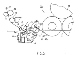
- Fig. 3 is a schematical illustration of an exemplifying embodiment of the invention as applied in a carrier-drum slitter 20.
- the web iW is introduced in a way in itself known, guided by the guide rolls 31,32,33, into the device in accordance with the invention, from which the component webs are passed, in this embodiment, into a carrier-drum slitter 20, by the intermediate of a first roll 21 and a second roll 22, to be wound into a roll 23.
- the device for spreading of the component webs W1...W n consists of two bowed revolving rolls 10,11 and of a swing mechanism 15,16,17.
- a regulation mechanism 1213 the directional angles g1,g2 (Fig.
- the device comprises a first, bowed, revolving roll 10 fitted at one side of the web W and a second, bowed, revolving roll 11 fitted at the opposite side of the web W.
- the device further comprises a swing mechanism 15,16,17, by whose means the rolls 10,11 are affected to alter their deflection angles b1,b2 and thereby to provide the desired spreading C for the component webs W1...W n .
- the device is provided with a regulation mechanism 12,13, which corrects the directional angles g1,g2 of the rolls 10,11 and of the web W to correct values.
- This regulation mechanism 12,13 may be composed, e.g., of articulation arms 12,13, as is shown in Fig. 3.
- the directional angles g1,g2 are adjusted by means of the articulation arms 12,13 so that the directional angles g1,g2 of the rolls 10,11 relative the web W are always invariable, preferably 90 o .
- the rolls 10,11 that are used as spreader members may be fragmentary rolls or continuous, bowed rolls, or equivalent.
- the device in accordance with the invention is suitable for use in the spreading of component webs of a variety of web materials.
- the web material may consist of plastic film, fabric, paper, metal sheet, cardboardl or of equivalent material.
- the invention concerns a device for spreading of component webs (W1,W2...W n-1 ,W n ), comprising a first, bowed, revolving roll (10) fitted at one side of the web (W) and a second, bowed, revolving roll (11) fitted at the opposite side of the web (W), as well as a swing mechanism (15,16,17), which is fitted to act upon said rolls (10,11) so as to alter the deflection angles (b1,b2) of the component webs (W1,W2...W n-1 ,W n ) and thereby to produce the desired spreading (C) of the component webs (W1,W2...W n-1 ,W n ).
- the device is provided with a regulation mechanism (12,13), which is fitted to correct the directional angles (g1,g2) between said rolls (10,11) and the web (W) to the desired values with all values of the deflection angle (b1,b2).
Landscapes
- Folding Of Thin Sheet-Like Materials, Special Discharging Devices, And Others (AREA)
- Registering, Tensioning, Guiding Webs, And Rollers Therefor (AREA)
Abstract
Description
- The invention concerns a device for spreading of component webs, comprising a first, bowed, revolving roll fitted at one side of the web and a second, bowed, revolving roll fitted at the opposite side of the web, as well as a swing mechanism, which is fitted to act upon said rolls so as to alter the deflection angles of the component webs and thereby to produce the desired spreading of the component webs.
- By means of spreading of the component webs, attempts are made to separate the individual strips slit, e.g., in a slitter in the lateral direction sufficiently far from each other to ensure detaching of the reels from each other. In the spreading of the component webs, the objective is to perform the lateral shifting of the web so that lateral gliding of the web in the spreader member is avoided, by guiding the web by means of a first spreader member by deflecting towards the side and by means of a second spreader member so that its original running direction is restored. In prior art, as spreader members, for example, rods, beams or revolving roll mantles mounted on an axle bent into curved form are employed. A revolving roll mantle may be composed, e.g., of rigid mantle units, or it may be continuous and elastic. The mantle units may also be separate. In a spreader with a revolving mantle, the problem is, however, often encountered that the direction of movement of the web and the vector of rotation that represents the rolling of the revolving roll mantle are, at least at some location on the mantle, placed obliquely to each other. In such a case, the web is affected by a force component which attempts to shift the web by sliding on the roll mantle in the axial direction corresponding to the longitudinal direction of the roll mantle.
- As is well known, the extent of the separation gap between the component webs is adjusted either by altering the curve radius, by altering the gap between the rolls or the gap between the spreader members, or by altering the deflection angle of the web. If the size of the spreading gap is adjusted by altering the distance between the spreader members, this affects the size of the machine concerned, and thereby the use of this possibility of regulation is complex. If regulation based on alteration of the curve radius is used in the spreading of the component webs, the use of this mode of regulation requires very high precision, for even a little change in the curve radius has a strong effect on the distance between the component webs.
- The commonest mode of adjusting the magnitude of the separation gaps between the component webs is to perform it by adjusting the angle of deflection of the web across the spreader members. In such a case, the web makes a steeper or less steep angle when it passes over the spreader members, whereby the distance between the component webs is changed.
- When the angles of deflection of the web at the spreader devices are altered, the directional angles of the arcs relative the web are also altered. A change in the directional angle of an arc causes a lateral component of rolling in the web, which causes problems, because the slide friction force between the web and the spreader rolls causes disturbance in the spreading. As is well known, the directional angles have been adjusted manually, which is slow and difficult.
- The object of the present invention is to provide a device for spreading of component webs wherein the factors explained above do not cause problems, because the correcting of the directional angle is mechanically positively controlled.
- In view of achieving the objectives stated above and those that will come out later, the device in accordance with the invention is mainly characterized in that the device is provided with a regulation mechanism, which is fitted to correct the directional angle between said rolls and the web to the desired value with all values of the deflection angle.
- By means of the device in accordance with the invention, the directional angles between the arcs in the spreader members and the web are automatically regulated to the correct values when the deflection angles of the web are adjusted as the amount of spreading is being increased or reduced.
- In the following, the device in accordance with the invention will be described in more detail with reference to the figures in the accompanying drawing.
- Figure 1 is a schematical illustration of the principle of the deflection spreader as viewed from below.
- Figure 2 is a schematical side view of the principle of deflection spreading and of its control quantities.
- Figure 3 is a schematical illustration of a device in accordance with the invention.
- In Fig. 1 it is shown schematically how the slit component webs W₁,W₂...Wn-1,Wn arrive at the
first spreader roll 10 in a direction in which the mantle of theroll 10 rolls directly in the direction P of running of the web W. The component webs W₁...Wn are turned around thearc 10′ of the roll 10 (Fig. 2) in the direction R₁₀ of rolling of thefirst roll 10, being at the same time deflected outwards, each component web W₁...Wn in its own direction P₁,P₂...Pn. Gaps C are opened between the component webs W₁...Wn. Each component web W₁...Wn arrives at thesecond roll 11 in the direction R₁₁ of rolling of the mantle, being turned along with the mantle to the original straight direction P of running. The component webs W₁...Wn are detached from thesecond spreader roll 11, and there are the necessary separation gaps C between the component webs W₁...Wn. - Fig. 2 is a schematical illustration of quantities that affect the deflection spreading. In the figure, the web is denoted with the reference W, the web running below the
first spreader roll 10 while itsarc 10′ spreads the web into component webs W₁...Wn. Hereupon the component webs W₁...Wn run over thesecond spreader roll 11, whosearc 11′ turns the component webs W₁...Wn into their original direction P of running (Fig. 1). In the figure, the curve radii of the spreadingarcs 10′,11′ are denoted with the references r₁,r₂. The distance between thespreader rolls reference 1. The deflection angles of the web in across therolls arcs 10′,11′ relative the web in are denoted with g₁ and g₂. - Fig. 3 is a schematical illustration of an exemplifying embodiment of the invention as applied in a carrier-
drum slitter 20. The web iW is introduced in a way in itself known, guided by theguide rolls drum slitter 20, by the intermediate of afirst roll 21 and asecond roll 22, to be wound into aroll 23. In this exemplifying embodiment, the device for spreading of the component webs W₁...Wn consists of two bowedrevolving rolls swing mechanism regulation mechanism rolls swing mechanism piece 15 is turned by means of ajack 16 around an articulatedjoint 17, whereby the deflection angles b₁,b₂ of the paper web W across therolls - As is shown in Figs. 1,2 and 3, the device comprises a first, bowed, revolving
roll 10 fitted at one side of the web W and a second, bowed, revolvingroll 11 fitted at the opposite side of the web W. The device further comprises aswing mechanism rolls regulation mechanism rolls regulation mechanism articulation arms articulation arms rolls rolls - The device in accordance with the invention is suitable for use in the spreading of component webs of a variety of web materials. The web material may consist of plastic film, fabric, paper, metal sheet, cardboardl or of equivalent material.
- Above, the invention has been described with reference to one advantageous exemplifying embodiment of same only. This is, however, by no means supposed to confine the invention to this exemplifying embodiment alone, but many variations and modifications are possible within the scope of the inventive idea defined in the following patent claims.
- The invention concerns a device for spreading of component webs (W₁,W₂...Wn-1,Wn), comprising a first, bowed, revolving roll (10) fitted at one side of the web (W) and a second, bowed, revolving roll (11) fitted at the opposite side of the web (W), as well as a swing mechanism (15,16,17), which is fitted to act upon said rolls (10,11) so as to alter the deflection angles (b₁,b₂) of the component webs (W₁,W₂...Wn-1,Wn) and thereby to produce the desired spreading (C) of the component webs (W₁,W₂...Wn-1,Wn). The device is provided with a regulation mechanism (12,13), which is fitted to correct the directional angles (g₁,g₂) between said rolls (10,11) and the web (W) to the desired values with all values of the deflection angle (b₁,b₂).
Claims (2)
Applications Claiming Priority (2)
| Application Number | Priority Date | Filing Date | Title |
|---|---|---|---|
| FI895581A FI90523C (en) | 1989-11-22 | 1989-11-22 | Device for separating the partial webs |
| FI895581 | 1989-11-22 |
Publications (2)
| Publication Number | Publication Date |
|---|---|
| EP0431275A2 true EP0431275A2 (en) | 1991-06-12 |
| EP0431275A3 EP0431275A3 (en) | 1991-10-30 |
Family
ID=8529399
Family Applications (1)
| Application Number | Title | Priority Date | Filing Date |
|---|---|---|---|
| EP19900118894 Withdrawn EP0431275A3 (en) | 1989-11-22 | 1990-10-02 | Device for spreading of component webs |
Country Status (4)
| Country | Link |
|---|---|
| EP (1) | EP0431275A3 (en) |
| JP (1) | JPH03186555A (en) |
| CA (1) | CA2029193A1 (en) |
| FI (1) | FI90523C (en) |
Cited By (12)
| Publication number | Priority date | Publication date | Assignee | Title |
|---|---|---|---|---|
| US5185052A (en) * | 1990-06-06 | 1993-02-09 | The Procter & Gamble Company | High speed pleating apparatus |
| WO1993006035A1 (en) * | 1991-09-14 | 1993-04-01 | Beloit Technologies, Inc. | Width adjusting machine for reel cutters |
| AT397953B (en) * | 1991-12-04 | 1994-08-25 | Pfauser Alexander | Winding machine and winding method for web-like material, in particular for bandages |
| US5533659A (en) * | 1991-09-14 | 1996-07-09 | Beloit Technologies, Inc. | Dust removal system |
| DE29509516U1 (en) * | 1995-06-14 | 1996-10-17 | Beloit Technologies, Inc., Wilmington, Del. | Separating device for winding devices for material webs that are longitudinally divided into several partial webs |
| US5911384A (en) * | 1997-09-30 | 1999-06-15 | Jagenberg Papiertechnik Gmbh | Unloading device for paper-winding machine |
| US6082660A (en) * | 1996-06-14 | 2000-07-04 | Beloit Technologies, Inc. | Separating device for winding devices for material webs, longitudinally divided into several partial webs |
| EP1792858A3 (en) * | 2005-12-03 | 2007-11-28 | Voith Paper Patent GmbH | Roll winding device |
| DE102009010814A1 (en) | 2008-03-03 | 2009-09-10 | Metso Paper, Inc. | Device for separating partial webs |
| EP2447044A1 (en) | 2010-11-01 | 2012-05-02 | DSM IP Assets B.V. | Foil guiding system for additive fabrication |
| EP2703326A1 (en) | 2012-08-29 | 2014-03-05 | Metso Paper Inc. | Method for separating partial webs in a slitter winder |
| DE202024107089U1 (en) | 2023-12-07 | 2025-01-20 | Valmet Technologies Oy | roll cutter |
Family Cites Families (5)
| Publication number | Priority date | Publication date | Assignee | Title |
|---|---|---|---|---|
| DE2007569B1 (en) * | 1970-02-19 | 1971-04-22 | Erwin Kampf Maschinenfabrik | Roller mill for pulling apart strips |
| US4410122A (en) * | 1981-06-01 | 1983-10-18 | Beloit Corporation | Device for widthwise control of web material and method |
| JPS5974848A (en) * | 1982-10-23 | 1984-04-27 | Konishiroku Photo Ind Co Ltd | Separated transport method of band type material |
| FI69440C (en) * | 1983-07-22 | 1986-02-10 | Waertsilae Oy Ab | ANORDING FROM THE BANK |
| JPH0658522B2 (en) * | 1986-08-13 | 1994-08-03 | 富士写真フイルム株式会社 | Color photographic processing composition |
-
1989
- 1989-11-22 FI FI895581A patent/FI90523C/en not_active IP Right Cessation
-
1990
- 1990-10-02 EP EP19900118894 patent/EP0431275A3/en not_active Withdrawn
- 1990-11-02 CA CA002029193A patent/CA2029193A1/en not_active Abandoned
- 1990-11-22 JP JP2320552A patent/JPH03186555A/en active Pending
Cited By (18)
| Publication number | Priority date | Publication date | Assignee | Title |
|---|---|---|---|---|
| US5185052A (en) * | 1990-06-06 | 1993-02-09 | The Procter & Gamble Company | High speed pleating apparatus |
| WO1993006035A1 (en) * | 1991-09-14 | 1993-04-01 | Beloit Technologies, Inc. | Width adjusting machine for reel cutters |
| US5533659A (en) * | 1991-09-14 | 1996-07-09 | Beloit Technologies, Inc. | Dust removal system |
| AT397953B (en) * | 1991-12-04 | 1994-08-25 | Pfauser Alexander | Winding machine and winding method for web-like material, in particular for bandages |
| DE29509516U1 (en) * | 1995-06-14 | 1996-10-17 | Beloit Technologies, Inc., Wilmington, Del. | Separating device for winding devices for material webs that are longitudinally divided into several partial webs |
| WO1997000222A1 (en) * | 1995-06-14 | 1997-01-03 | Beloit Technologies, Inc. | Separating device for winding devices for material webs, longitudinally divided into several partial webs |
| US6082660A (en) * | 1996-06-14 | 2000-07-04 | Beloit Technologies, Inc. | Separating device for winding devices for material webs, longitudinally divided into several partial webs |
| US5911384A (en) * | 1997-09-30 | 1999-06-15 | Jagenberg Papiertechnik Gmbh | Unloading device for paper-winding machine |
| EP1792858A3 (en) * | 2005-12-03 | 2007-11-28 | Voith Paper Patent GmbH | Roll winding device |
| DE102009010814A1 (en) | 2008-03-03 | 2009-09-10 | Metso Paper, Inc. | Device for separating partial webs |
| AT506495B1 (en) * | 2008-03-03 | 2012-05-15 | Metso Paper Inc | DEVICE FOR SEPARATING PARTICLES |
| DE102009010814B4 (en) * | 2008-03-03 | 2017-04-13 | Valmet Technologies, Inc. | Device for separating partial webs |
| EP2447044A1 (en) | 2010-11-01 | 2012-05-02 | DSM IP Assets B.V. | Foil guiding system for additive fabrication |
| WO2012060696A1 (en) | 2010-11-01 | 2012-05-10 | Dsm Ip Assets B.V. | Foil guiding system for additive fabrication |
| EP3075522A1 (en) | 2010-11-01 | 2016-10-05 | DSM IP Assets B.V. | Foil guiding system for additive fabrication |
| EP2703326A1 (en) | 2012-08-29 | 2014-03-05 | Metso Paper Inc. | Method for separating partial webs in a slitter winder |
| US9260266B2 (en) | 2012-08-29 | 2016-02-16 | Valmet Technologies, Inc. | Method for separating partial webs in a slitter winder |
| DE202024107089U1 (en) | 2023-12-07 | 2025-01-20 | Valmet Technologies Oy | roll cutter |
Also Published As
| Publication number | Publication date |
|---|---|
| FI90523B (en) | 1993-11-15 |
| CA2029193A1 (en) | 1991-05-23 |
| FI895581L (en) | 1991-05-23 |
| FI90523C (en) | 1994-02-25 |
| JPH03186555A (en) | 1991-08-14 |
| EP0431275A3 (en) | 1991-10-30 |
| FI895581A0 (en) | 1989-11-22 |
Similar Documents
| Publication | Publication Date | Title |
|---|---|---|
| EP0431275A2 (en) | Device for spreading of component webs | |
| EP0854233B1 (en) | Process and apparatus for the damping of vibrations for rolls in contacting rotation | |
| US4669646A (en) | Arrangement for web spreading | |
| US3682362A (en) | Web edge sensing and guiding apparatus | |
| EP0026335A1 (en) | Control device on apparatuses for winding webs of material on rolls and method of winding pressure-sensitive webs of material on rolls | |
| DE2713917B2 (en) | Process for achieving a thickness of the press nip of a calender that is constant over the entire length of the roll | |
| WO2010124969A1 (en) | Device for compensating variations in tension and/or for adjusting tension on a conveyed flexible material strand | |
| GB2157273A (en) | Winding paper web | |
| GB2053856A (en) | Device for regulating the tension of a travelling web | |
| US6001179A (en) | Coating medium applicator with guide surface | |
| DE10247456A1 (en) | Arrangement for guiding continuous path, e.g. in printer or copier, has two rollers with axes are parallel to each other in plane and held by a frame pivotable about two rotation axes | |
| EP1484443B1 (en) | Device and method for controlling the tension force of a moving web | |
| EP0136389B1 (en) | Warp let-off control mechanism for looms | |
| EP1144291B1 (en) | Method and device for reducing the volume or pressure of a fluid which is driven through an opening by moving surfaces | |
| WO2016197158A1 (en) | Winding machine for winding material to be wound | |
| DE102009010814B4 (en) | Device for separating partial webs | |
| EP3819241B1 (en) | Method of guiding a web | |
| EP0933320B1 (en) | Reel winder | |
| EP0874960A1 (en) | Device for correcting the course of a belt | |
| EP0663362A1 (en) | Apparatus for guiding and maintaining a web expanded | |
| DE1959065A1 (en) | Patentwesen, Ost-Berlin WPI36706 Loading device for a web guided between two pairs of processing rollers | |
| EP0945379B1 (en) | Roll winding device | |
| DE2334779A1 (en) | TENSION CONTROL DEVICE FOR A FABRIC | |
| DE3244977C2 (en) | Pressure device on a winding roll | |
| DE10249396A1 (en) | Arrangement for the indirect or direct detection of a local web tension of a running material web at at least one web transverse position |
Legal Events
| Date | Code | Title | Description |
|---|---|---|---|
| PUAI | Public reference made under article 153(3) epc to a published international application that has entered the european phase |
Free format text: ORIGINAL CODE: 0009012 |
|
| 17P | Request for examination filed |
Effective date: 19901231 |
|
| AK | Designated contracting states |
Kind code of ref document: A2 Designated state(s): DE ES FR GB SE |
|
| PUAL | Search report despatched |
Free format text: ORIGINAL CODE: 0009013 |
|
| AK | Designated contracting states |
Kind code of ref document: A3 Designated state(s): DE ES FR GB SE |
|
| RHK1 | Main classification (correction) |
Ipc: B65H 35/02 |
|
| STAA | Information on the status of an ep patent application or granted ep patent |
Free format text: STATUS: THE APPLICATION HAS BEEN WITHDRAWN |
|
| 18W | Application withdrawn |
Withdrawal date: 19911203 |