EP0431147B1 - Mounting frame for electronic equipment - Google Patents
Mounting frame for electronic equipment Download PDFInfo
- Publication number
- EP0431147B1 EP0431147B1 EP90911214A EP90911214A EP0431147B1 EP 0431147 B1 EP0431147 B1 EP 0431147B1 EP 90911214 A EP90911214 A EP 90911214A EP 90911214 A EP90911214 A EP 90911214A EP 0431147 B1 EP0431147 B1 EP 0431147B1
- Authority
- EP
- European Patent Office
- Prior art keywords
- frame
- vertical
- members
- frame members
- horizontal
- Prior art date
- Legal status (The legal status is an assumption and is not a legal conclusion. Google has not performed a legal analysis and makes no representation as to the accuracy of the status listed.)
- Expired - Lifetime
Links
- 230000035939 shock Effects 0.000 claims description 11
- 239000000463 material Substances 0.000 claims description 7
- 229910052782 aluminium Inorganic materials 0.000 claims description 6
- XAGFODPZIPBFFR-UHFFFAOYSA-N aluminium Chemical compound [Al] XAGFODPZIPBFFR-UHFFFAOYSA-N 0.000 claims description 6
- 239000004411 aluminium Substances 0.000 claims 1
- 238000003466 welding Methods 0.000 description 4
- 238000005452 bending Methods 0.000 description 3
- 238000010276 construction Methods 0.000 description 3
- 238000004519 manufacturing process Methods 0.000 description 3
- 238000001125 extrusion Methods 0.000 description 2
- 238000000034 method Methods 0.000 description 2
- FYYHWMGAXLPEAU-UHFFFAOYSA-N Magnesium Chemical compound [Mg] FYYHWMGAXLPEAU-UHFFFAOYSA-N 0.000 description 1
- 239000004698 Polyethylene Substances 0.000 description 1
- 230000007812 deficiency Effects 0.000 description 1
- 230000002452 interceptive effect Effects 0.000 description 1
- 229910052749 magnesium Inorganic materials 0.000 description 1
- 239000011777 magnesium Substances 0.000 description 1
- 229910052751 metal Inorganic materials 0.000 description 1
- 239000002184 metal Substances 0.000 description 1
- 238000012986 modification Methods 0.000 description 1
- 230000004048 modification Effects 0.000 description 1
- -1 polyethylene Polymers 0.000 description 1
- 229920000573 polyethylene Polymers 0.000 description 1
- 239000007787 solid Substances 0.000 description 1
- 238000003860 storage Methods 0.000 description 1
- WFKWXMTUELFFGS-UHFFFAOYSA-N tungsten Chemical compound [W] WFKWXMTUELFFGS-UHFFFAOYSA-N 0.000 description 1
- 229910052721 tungsten Inorganic materials 0.000 description 1
- 239000010937 tungsten Substances 0.000 description 1
Images




Classifications
-
- B—PERFORMING OPERATIONS; TRANSPORTING
- B65—CONVEYING; PACKING; STORING; HANDLING THIN OR FILAMENTARY MATERIAL
- B65D—CONTAINERS FOR STORAGE OR TRANSPORT OF ARTICLES OR MATERIALS, e.g. BAGS, BARRELS, BOTTLES, BOXES, CANS, CARTONS, CRATES, DRUMS, JARS, TANKS, HOPPERS, FORWARDING CONTAINERS; ACCESSORIES, CLOSURES, OR FITTINGS THEREFOR; PACKAGING ELEMENTS; PACKAGES
- B65D81/00—Containers, packaging elements, or packages, for contents presenting particular transport or storage problems, or adapted to be used for non-packaging purposes after removal of contents
- B65D81/02—Containers, packaging elements, or packages, for contents presenting particular transport or storage problems, or adapted to be used for non-packaging purposes after removal of contents specially adapted to protect contents from mechanical damage
- B65D81/05—Containers, packaging elements, or packages, for contents presenting particular transport or storage problems, or adapted to be used for non-packaging purposes after removal of contents specially adapted to protect contents from mechanical damage maintaining contents at spaced relation from package walls, or from other contents
- B65D81/07—Containers, packaging elements, or packages, for contents presenting particular transport or storage problems, or adapted to be used for non-packaging purposes after removal of contents specially adapted to protect contents from mechanical damage maintaining contents at spaced relation from package walls, or from other contents using resilient suspension means
-
- H—ELECTRICITY
- H05—ELECTRIC TECHNIQUES NOT OTHERWISE PROVIDED FOR
- H05K—PRINTED CIRCUITS; CASINGS OR CONSTRUCTIONAL DETAILS OF ELECTRIC APPARATUS; MANUFACTURE OF ASSEMBLAGES OF ELECTRICAL COMPONENTS
- H05K7/00—Constructional details common to different types of electric apparatus
- H05K7/18—Construction of rack or frame
- H05K7/183—Construction of rack or frame support rails therefor
-
- H—ELECTRICITY
- H02—GENERATION; CONVERSION OR DISTRIBUTION OF ELECTRIC POWER
- H02B—BOARDS, SUBSTATIONS OR SWITCHING ARRANGEMENTS FOR THE SUPPLY OR DISTRIBUTION OF ELECTRIC POWER
- H02B1/00—Frameworks, boards, panels, desks, casings; Details of substations or switching arrangements
- H02B1/01—Frameworks
- H02B1/013—Profiles for cabinet frames
-
- H—ELECTRICITY
- H02—GENERATION; CONVERSION OR DISTRIBUTION OF ELECTRIC POWER
- H02B—BOARDS, SUBSTATIONS OR SWITCHING ARRANGEMENTS FOR THE SUPPLY OR DISTRIBUTION OF ELECTRIC POWER
- H02B1/00—Frameworks, boards, panels, desks, casings; Details of substations or switching arrangements
- H02B1/01—Frameworks
- H02B1/014—Corner connections for frameworks
Definitions
- This invention relates to a mounting frame for protecting sensitive electronic equipment against damage caused by impacts and excessive vibration during shipping and handling.
- a further disadvantage of a welded rack system is the storage space required to keep finished racks in stock in order to fill orders promptly.
- An object of the present invention is to provide a low cost rack and mounting frame that is capable of supporting electronic equipment modules inside a container and preventing damage thereto caused by impacts and vibration during shipping and handling of the container.
- a further object of the present invention is to provide a rack and mounting frame having frame members that can be assembled quickly and easily in accordance with precise dimensional tolerances, and that can be disassembled if desired.
- the electronic rack and mounting frame comprises a plurality of vertical and horizontal frame members formed with a hollow interior and a plurality of side frame members.
- a first connecting means is provided within the hollow interiors of the vertical and horizontal frame members for detachably securing the distal ends of the vertical frame members to the distal ends of the horizontal frame members to form a front frame panel and a rear frame panel.
- a second connecting means detachably secures the distal ends of the side frame members to the front and rear frame panels.
- the vertical and horizontal frame members can be made hollow throughout their entire lengths from an extrudable, high tensile strength aluminum material.
- the vertical frame members of the front frame panel have a plurality of threaded mounting holes spaced a distance corresponding to the spacing of a plurality of mounting holes in the electronic equipment module that is to be mounted to the frame.
- the hollow vertical and horizontal frame members have a substantially rectangular cross-section such that the frame members are defined by a front and rear wall and a pair of side walls.
- the first connecting means comprises an L-shaped, internal splice member having a vertical leg portion and a horizontal leg portion which are joined at right angles at a central portion.
- the vertical and horizontal leg portions of the internal splice member have a cross-sectional shaped corresponding approximately to the cross-sectional shape of the hollow interiors of the vertical and horizontal frame members so that the vertical leg portion fits within the hollow interior of one of the vertical frame members and the horizontal leg portion fits within the hollow interior of one of the horizontal frame members.
- the distal ends of the vertical frame members have a cut-out portion in one of the side walls such that the vertical leg portion and the central portion of the internal splice member is received inside the hollow interior of the vertical frame member.
- the distal ends of the vertical frame members are also formed with an angular surface corresponding to an angular surface of the central portion of the internal splice members.
- the cut-out portions are dimensioned such that each vertical leg portion and central portion of the internal splice member is received within the hollow interior of the vertical frame member to a point where the angular surface of the central portion is substantially aligned with the angular surface of the vertical frame member and an outer surface of the horizontal leg portion of the internal splice member is substantially aligned with an outer end surface of the vertical frame member.
- each internal splice member has at least one hole formed therein such that when the vertical leg member is received within the hollow interior of the vertical frame member, the hole aligns with at least one corresponding hole in the front and rear walls of the vertical frame member.
- the vertical leg of the internal splice member can be secured to the vertical frame members by pin means, such as a headless roll spring pin, fitted within the aligned holes.
- the second connecting means includes an L-shaped, external splice member having a vertical leg portion and a horizontal leg portion which are joined at right angles at a central portion.
- Each vertical leg portion of the erternal splice members is detachably secured to one of the distal ends of the vertical frame members and each horizontal leg portion of the external splice members is detachably secured to one of the distal ends of the horizontal frame members.
- At least one hole is formed in the vertical and horizontal leg portions of each external splice member and at least one corresponding hole is formed in the front and rear walls of the vertical and horizontal frame members.
- Corresponding holes are provided in the vertical and horizontal leg portions of the internal splice members. In that way, a plurality of screws can engage the holes to detachably secure the external splice members to the front and rear frame panels.
- the side frame members are secured at their distal ends to the external splice members.
- the central portion of each external splice member is provided with an angled outer surface with respect to the outer surfaces of the vertical and horizontal leg portions of the external splice member.
- the side frame members have a central portion and outer portions angled with respect to the central portion such that an inner surface of each side member has a contour corresponding to that of the outer surface of a corresponding external splice member.
- the distal ends of each side frame member is provided with at least one hole which is aligned with at least one threaded hole in the outer surfaces of the external splice members so that the side frame members can be detachably secured to the external splice members by way of screws.
- the rack and mounting frame according to the present invention can comprise additional features including a horizontally-extending ledge portion provided on the horizontal frame members of the front frame panel for preventing foreign materials from contaminating the internal components of the electronic equipment modules.
- the frame can be reinforced by diagonally-extending brace members detachably secured to the side frame members.
- the side frame members are provided with a plurality of shock mounts for supporting the frame within a hollow interior of a transport container.
- FIG. 1 represents a prior art rack and mounting system 10 for shipping and handling sensitive electronic equipment 20.
- the rack and mounting system 10 employs a rack frame 11 that fits within a heavy-duty, molded container 12.
- the electronic equipment 20 is provided with a bezeled front panel 21 in which holes 22 are formed for securing the equipment to the rack frame 11.
- the rack system 10 is constructed from a plurality of vertical and horizontal members 13, 14 extruded from aluminum which are TIG-welded at their distal ends to form a rectangular parallelpiped frame structure.
- a pair of rubber shock mounts 15 are mounted at a 45 degree angle, in spaced relation, on each horizontal member 14 running in the fore-to-aft direction.
- the shock mounts 15 are dimensioned so that they engage corner brackets (not shown) mounted inside the molded container 12, thereby suspending the rack frame 11 within the hollow interior thereof.
- the vertical extrusion members 13 forming the front panel 16 of the rack frame 11 are provided with an Electronic Industries Association (EIA) standard hole pattern 17, the spacing of which corresponds to that of holes 22 provided in the front panel 21 of electronic equipment module 20.
- EIA Electronic Industries Association
- the electronic equipment modules 20 are secured to the rack frame 11 by bolts 23 that extend through holes 22 in front panels 21 and into holes 17 in vertical frame members 13.
- a nut held by a spring clip (not shown) allows the bolt to be securely tightened against the frame.
- the vertical extrusion members 13 will be subjected to considerable bending forces in the fore-to-aft and lateral directions.
- the rack and mounting system of FIG. 2 is considered strong enough to adequately protect the sensitive electronic equipment modules supported therein from high impact forces, the TIG welding of the extruded frame members 13, 14 is time-consuming which, consequently, increases the cost of manufacturing the rack frame 11.
- the TIG welding further distorts the frame members which must be laboriously corrected.
- the accuracy of the distance between the two rows of mounting holes is difficult to control in the rack system of FIG. 2 due to variations in the shrinkage of the welds.
- the welds permanently secure the frame members of rack frame 11 together, it is impossible to disassemble frame 11 if desired.
- the rack system 30 is shown in FIG. 3 and is designed to overcome the deficiencies in the prior art rack system described above.
- Rack system 30 like the prior art device of FIG. 2, uses a rectangular parallelpiped frame structure comprising vertical and horizontal frame members 31, 32 and side frame members 33, all of which are preferably made from extruded, high tensile strength aluminum 6061-T6 or 6005-T5.
- frame members 31-33 could be made out of magnesium or any other extrudable material.
- the side frame members 33 are provided with a pair of rubber shock mounts 59, similar to those disclosed in connection with the prior art device shown in FIG 2, for mounting the rack frame 30 within the hollow interior of a transport container.
- the vertical and horizontal frame members 31, 32 that make up the front and back frame panels 34, 35 of the rack frame 30 are extruded tubes having a rectangular cross-section with hollow interiors 36, as illustrated in FIG. 4.
- the vertical frame members 31 differ slightly in their construction from the horizontal frame members 32.
- the vertical frame members 31 that constitute front frame panel 34 are provided with a standard pattern of threaded mounting holes 37 for No. 10-32 screws.
- the holes 37 extend the length of the front and rear walls 38, 39 of frame member 31 for securing the front bezel panel of an electronic equipment module to the frame.
- the distal end 40 of each vertical member 31 is machined to form a U-shaped angular surface 41.
- the front and rear walls 49 of the horizontal frame members 32 are preferably constructed with a thickness of .1 inches to provide sufficient strength to resist bending moments.
- the height of each horizontal frame member 32 is preferably .62 inches to provide sufficient bending stiffness to maintain the squareness of the front and rear rack faces when the rack is in an unloaded condition.
- the height of the horizontal frame members 32 does not significantly add to the height of the rack when the space required for the shock mounts 59 is taken into account.
- the width of the vertical frame members is preferably .625 inches with a total rack width of 19 inches--the same width as that of standard bezel plates of most electronic equipment modules.
- the thickness of the front and rear walls 38, 39 of the vertical frame members 31 is .25 inches so that the screws that fasten the bezel plates and other members to the members 31 are threadably engaged sufficiently to utilize their tensile strength.
- the vertical leg portion 61 of an internal splice member 60 is inserted into the hollow interior 36 of a vertical member 31.
- Each distal end 40 of the vertical member 31 has a rectangular cut-out portion 42 along its inner side wall 47.
- the cut-out 42 is dimensioned to allow vertical leg portion 61 and central portion 63 of internal splice member 60 to be received inside the hollow interior 36 of the vertical frame member 31 up to the point where the angular surface 64 of central portion 63 of the internal splice member 60 is substantially aligned with the angular surface 41 of the vertical frame member 31.
- the upper horizontal surface 65 of the horizontal leg portion 62 is substantially aligned with the outermost end surface 43 of the vertical frame member 31.
- a pair of pin holes 66 are drilled through the vertical leg portion 61 of each internal splice member 60. Pin holes 66 are arranged such that when the vertical leg portion 61 is positioned within the hollow interior 36 of a vertical frame member 31, the pin holes 66 align with corresponding pin holes 44 formed in the front and rear walls 38, 39 near the distal end 40 of vertical frame member 31.
- each internal splice member 60 is fastened to its corresponding vertical frame member 31 by way of roll spring pins 45 which fit through the aligned pin holes 44, 66 in the vertical frame member 31 and vertical leg portion 61 of internal splice member 60.
- Roll spring pins are preferred for their high shear strength, although other pins, such as spiral or solid pins, could also be used.
- the spring pins 45 are headless having a length less than the width of side walls 47 and, consequently, pins 45 fit between the upper two EIA standard holes 37 of the vertical frame members 31 without interfering with the holes 37 or the bezel plate 81 of an electronic equipment module 80 mounted to vertical frame members 31 (FIG. 9).
- the internal splice members 60 are machined to fit closely in the vertical frame members 31 in the fore-to-aft direction, but need not fit closely in the lateral direction.
- the internal splice members 60 are also machined to provide a close fit inside the horizontal frame members 32 in the lateral direction, but not in the vertical direction.
- the external splice member 70 is made up of a vertical leg portion 71 and a horizontal leg portion 72 connected at right angles by a central portion 73 such that the outer face surfaces 76 of leg portions 71, 72 form a 45 degree angle with the outer face surface 75 of central portion 73.
- a pair of unthreaded holes 74 are formed through each of the vertical and horizontal leg portions 71, 72 of the external splice member 70.
- Holes 74 in the vertical leg portion 71 align with two threaded holes 37 in the upper portion of the front and rear walls 38, 39 of vertical frame member 31, and align with unthreaded holes 67 in the vertical leg portion of the internal splice member 60.
- Holes 74 in the horizontal leg portion 72 are aligned with unthreaded holes 48 in the front and rear walls 49 of horizontal frame member 32 and with threaded holes 67a in the horizontal leg portion of the internal splice member 60.
- two screws 78 pass through the unthreaded holes 74 in the vertical leg portion 71 of each external splice member 70 and screw into the threaded holes 37 in the rear wall 39 of vertical frame member 31.
- Holes 67 in the vertical leg portion 61 of internal splice member 60 are slightly larger in diameter than the screws 78 that fasten the vertical leg portion 71 of the external splice member 70. That allows the screws 78 to protrude through the rear wall 39 with full thread engagement and, thus, maximize the strength of the attachment.
- Holes 67 also provide clearance for the screws that are used to attach a bezel plate to the frame and are threaded into the holes 37 on the front wall 38 of vertical frame members 31.
- Two screws 78 also pass through the unthreaded holes 74 in the horizontal leg portion 72 of the external splice member 70 and through the unthreaded holes 48 in the rear wall 49 of the horizontal frame member 32. Screws 78 are threaded into holes 67a in the horizontal leg portion 62 of internal splice member 60. Two additional screws 79 pass through unthreaded holes 48 in the front wall 49 of horizontal frame member 32 and screw into the threaded holes 67a in the horizontal leg portion 62 of internal splice member 60.
- the side frame members 33 are secured at each distal end 53 to the external splice member 70 secured in each corner of the front and rear frame panels 34, 35.
- the inner surface width of central portion 51 of the side frame members 33 corresponds approximately to the outer surface length of angular portion 73 of the external splice member 70.
- the width of the outer portions 52 of the side frame members 33 corresponds approximately to the lengths of the vertical and horizontal leg portions 71, 72 of the external splice member 70.
- the lower surfaces 54 of the side frame members 33 at their distal ends 53 lie in flat engagement with the outer surfaces 75, 76 of the external splice member 70.
- the side frame member 33 is laid over the external splice member 70 up to the point that the outer end surface 55 abuts the side walls 39, 49 of vertical and horizontal frame members 31, 32. In that position, holes 56 in the distal end 53 of each side frame member 33 align with corresponding holes 77 threaded in the central portion 73 and the vertical and horizontal leg portions 71, 72 of the external splice member 70. Screws 57 can then be passed through the aligned holes 56, 77 to firmly secure each side frame member 33 to its respective external splice members 70.
- Each electronic equipment module 80 can be mounted to the rack 30, as shown in FIG. 9.
- Each electronic equipment module is provided with a front bezel panel 81 which is an integral part of the electronic equipment module 80 to be mounted.
- Holes 82 which follow EIA standards, are provided in bezel panel 81 so that holes 82 align with the threaded holes 37 provided along the front side wall 38 of the vertical frame members 31 comprising front frame panel 34. Screws 83 passing through holes 82 and threaded into holes 37 secure the electronic equipment module 80 to the rack 30.
- An additional feature of the present invention includes an outward projecting, horizontally-extending ledge 58 incorporated on the bottom edge of front side wall 49 of the top horizontal frame member 32 forming the front frame panel 34.
- the ledge 58 is dimensioned to extend over the top surface 84 of the bezel plate 81 of the uppermost electronic equipment module 80. This arrangement reduces the amount of dirt, moisture, and other foreign materials that deposit along the top surface 84 of bezel plate 81 and contaminate the internal components of the electronic equipment module 80.
- a ledge 58 is also provided along the top edge of the front side wall 49 of bottom horizontal frame member 32 for the same purpose.
- rigid rack frame 30 is sufficient to withstand most impacts and vibrations and, thus, prevent damage to sensitive electronic equipment secured thereto.
- rigid, diagonally-extending brace members 90 can be screwed to the outer portions 52 of side frame members 33 in the pattern illustrated in FIG. 10.
Landscapes
- Engineering & Computer Science (AREA)
- Microelectronics & Electronic Packaging (AREA)
- Mechanical Engineering (AREA)
- Casings For Electric Apparatus (AREA)
- Piezo-Electric Or Mechanical Vibrators, Or Delay Or Filter Circuits (AREA)
- Liquid Crystal (AREA)
- Electric Clocks (AREA)
- Mounting Of Printed Circuit Boards And The Like (AREA)
Abstract
Description
- This invention relates to a mounting frame for protecting sensitive electronic equipment against damage caused by impacts and excessive vibration during shipping and handling.
- Loading and transporting sensitive electronic equipment has presented numerous problems. Typically, such equipment is packed in a suitable shipping container. Even slight impacts or vibrations to the container, however, produce shock forces that may damage precision instruments if they are not properly supported within the container.
- To adequately protect electronic equipment, it is well known to use heavy-duty containers molded from polyethylene for high impact strength. An example of this type of shipping container is disclosed in U.S. Patent No. 4,284,202, issued August 8, 1981, to Barstow, Jr. It is also necessary to build into these rugged containers a shock-mitigation system that is capable of protecting the equipment from possible damage during shipping and other rough handling. One known system (marketed by HARDIGG INDUSTRIES, INC. (U.S.A.) and shown on Figure 2 of the drawings employs a mounting rack constructed from a plurality of welded vertical and horizontal frame members and shock mounts designed to hold the electronic equipment stationary and to absorb shocks.
- The problem with that prior art electronic rack mounting frames is that the vertical and horizontal members are Gas Shielded Tungsten Arc (TIG) welded together to form an integral frame structure. Although the welded rack frame is sufficiently strong to withstand most impacts and transmit the shock forces produced thereby from the shock mounts to the electronic equipment without damage, there are difficulties associated with its construction.
- First and foremost is the time required to weld the various frame members together and to correct any distortions caused during the welding process, which adds considerably to the cost of manufacturing the mounting rack. Because of imprecisions in the welding proces, it is difficult to maintain alignment of the mounting holes which are used to secure the electronic equipment modules to the rack. A further disadvantage of a welded rack system is the storage space required to keep finished racks in stock in order to fill orders promptly.
- An object of the present invention is to provide a low cost rack and mounting frame that is capable of supporting electronic equipment modules inside a container and preventing damage thereto caused by impacts and vibration during shipping and handling of the container. A further object of the present invention is to provide a rack and mounting frame having frame members that can be assembled quickly and easily in accordance with precise dimensional tolerances, and that can be disassembled if desired.
- To accomplish those and other objects, the electronic rack and mounting frame according to the present invention comprises a plurality of vertical and horizontal frame members formed with a hollow interior and a plurality of side frame members. A first connecting means is provided within the hollow interiors of the vertical and horizontal frame members for detachably securing the distal ends of the vertical frame members to the distal ends of the horizontal frame members to form a front frame panel and a rear frame panel. A second connecting means detachably secures the distal ends of the side frame members to the front and rear frame panels.
- The vertical and horizontal frame members can be made hollow throughout their entire lengths from an extrudable, high tensile strength aluminum material. The vertical frame members of the front frame panel have a plurality of threaded mounting holes spaced a distance corresponding to the spacing of a plurality of mounting holes in the electronic equipment module that is to be mounted to the frame. In addition, the hollow vertical and horizontal frame members have a substantially rectangular cross-section such that the frame members are defined by a front and rear wall and a pair of side walls.
- The first connecting means comprises an L-shaped, internal splice member having a vertical leg portion and a horizontal leg portion which are joined at right angles at a central portion. The vertical and horizontal leg portions of the internal splice member have a cross-sectional shaped corresponding approximately to the cross-sectional shape of the hollow interiors of the vertical and horizontal frame members so that the vertical leg portion fits within the hollow interior of one of the vertical frame members and the horizontal leg portion fits within the hollow interior of one of the horizontal frame members. The distal ends of the vertical frame members have a cut-out portion in one of the side walls such that the vertical leg portion and the central portion of the internal splice member is received inside the hollow interior of the vertical frame member. The distal ends of the vertical frame members are also formed with an angular surface corresponding to an angular surface of the central portion of the internal splice members. The cut-out portions are dimensioned such that each vertical leg portion and central portion of the internal splice member is received within the hollow interior of the vertical frame member to a point where the angular surface of the central portion is substantially aligned with the angular surface of the vertical frame member and an outer surface of the horizontal leg portion of the internal splice member is substantially aligned with an outer end surface of the vertical frame member.
- The vertical leg portion of each internal splice member has at least one hole formed therein such that when the vertical leg member is received within the hollow interior of the vertical frame member, the hole aligns with at least one corresponding hole in the front and rear walls of the vertical frame member. In this way, the vertical leg of the internal splice member can be secured to the vertical frame members by pin means, such as a headless roll spring pin, fitted within the aligned holes.
- The second connecting means includes an L-shaped, external splice member having a vertical leg portion and a horizontal leg portion which are joined at right angles at a central portion. Each vertical leg portion of the erternal splice members is detachably secured to one of the distal ends of the vertical frame members and each horizontal leg portion of the external splice members is detachably secured to one of the distal ends of the horizontal frame members. At least one hole is formed in the vertical and horizontal leg portions of each external splice member and at least one corresponding hole is formed in the front and rear walls of the vertical and horizontal frame members. Corresponding holes are provided in the vertical and horizontal leg portions of the internal splice members. In that way, a plurality of screws can engage the holes to detachably secure the external splice members to the front and rear frame panels.
- The side frame members are secured at their distal ends to the external splice members. The central portion of each external splice member is provided with an angled outer surface with respect to the outer surfaces of the vertical and horizontal leg portions of the external splice member. The side frame members have a central portion and outer portions angled with respect to the central portion such that an inner surface of each side member has a contour corresponding to that of the outer surface of a corresponding external splice member. The distal ends of each side frame member is provided with at least one hole which is aligned with at least one threaded hole in the outer surfaces of the external splice members so that the side frame members can be detachably secured to the external splice members by way of screws.
- The rack and mounting frame according to the present invention can comprise additional features including a horizontally-extending ledge portion provided on the horizontal frame members of the front frame panel for preventing foreign materials from contaminating the internal components of the electronic equipment modules. Furthermore, the frame can be reinforced by diagonally-extending brace members detachably secured to the side frame members. Also, the side frame members are provided with a plurality of shock mounts for supporting the frame within a hollow interior of a transport container.
- Other objects, features, and characteristics of the present invention, as well as the methods, operation, and functions of the related elements of the structure, and the combination of parts and economies of manufacture, will become more apparent upon consideration of the following description and the appended claims with reference to the accompanying drawings, all of which form a part of this specification, wherein like reference numerals designate corresponding parts in the various figures.
- The instant invention may best be understood with reference to the accompanying drawings wherein:
- FIG. 1 is a perspective view of a prior art rack and mounting frame installed within a shipping container;
- FIG. 2 is a perspective view of the prior art rack and mounting frame shown in FIG. 1;
- FIG. 3 is a perspective view of an assembled rack and mounting frame according to the present invention;
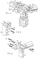
- FIG. 4 is an exploded perspective view of the connections between the various frame members of the rack and mounting frame according to the present invention;
- FIG. 5 is a perspective view of the connection between an internal splice member and a vertical frame member according to the present invention;
- FIG. 6 is a perspective view of the connection of an external splice member to the vertical and horizontal frame members according to the present invention;
- FIG. 7 is a perspective view of the connection of a side frame member to an external splice member according to the present invention;
- FIG. 8 is a rear view of the completed assembly shown in FIG. 7;
- FIG. 9 is a perspective view showing the connection of an electronic equipment module to the front panel of an assembled rack and mounting frame according to the present invention; and
- FIG. 10 is a perspective view of the rack and mounting frame according to the present invention that has been further strengthened with brace members.
- FIG. 1 represents a prior art rack and
mounting system 10 for shipping and handling sensitiveelectronic equipment 20. The rack andmounting system 10 employs a rack frame 11 that fits within a heavy-duty, moldedcontainer 12. Theelectronic equipment 20 is provided with abezeled front panel 21 in whichholes 22 are formed for securing the equipment to the rack frame 11. - Referring to FIG. 2, the
rack system 10 is constructed from a plurality of vertical andhorizontal members rubber shock mounts 15 are mounted at a 45 degree angle, in spaced relation, on eachhorizontal member 14 running in the fore-to-aft direction. Theshock mounts 15 are dimensioned so that they engage corner brackets (not shown) mounted inside the moldedcontainer 12, thereby suspending the rack frame 11 within the hollow interior thereof. - The
vertical extrusion members 13 forming thefront panel 16 of the rack frame 11 are provided with an Electronic Industries Association (EIA)standard hole pattern 17, the spacing of which corresponds to that ofholes 22 provided in thefront panel 21 ofelectronic equipment module 20. Theelectronic equipment modules 20 are secured to the rack frame 11 bybolts 23 that extend throughholes 22 infront panels 21 and intoholes 17 invertical frame members 13. A nut held by a spring clip (not shown) allows the bolt to be securely tightened against the frame. - If the
container 12 should suffer an impact during shipping or handling, thevertical extrusion members 13 will be subjected to considerable bending forces in the fore-to-aft and lateral directions. Although the rack and mounting system of FIG. 2 is considered strong enough to adequately protect the sensitive electronic equipment modules supported therein from high impact forces, the TIG welding of the extrudedframe members - The
rack system 30 according to the present invention is shown in FIG. 3 and is designed to overcome the deficiencies in the prior art rack system described above.Rack system 30, like the prior art device of FIG. 2, uses a rectangular parallelpiped frame structure comprising vertical andhorizontal frame members side frame members 33, all of which are preferably made from extruded, high tensile strength aluminum 6061-T6 or 6005-T5. Alternatively, frame members 31-33 could be made out of magnesium or any other extrudable material. Theside frame members 33 are provided with a pair of rubber shock mounts 59, similar to those disclosed in connection with the prior art device shown in FIG 2, for mounting therack frame 30 within the hollow interior of a transport container. - The vertical and
horizontal frame members back frame panels rack frame 30 are extruded tubes having a rectangular cross-section withhollow interiors 36, as illustrated in FIG. 4. Thevertical frame members 31 differ slightly in their construction from thehorizontal frame members 32. Thevertical frame members 31 that constitutefront frame panel 34 are provided with a standard pattern of threaded mountingholes 37 for No. 10-32 screws. Theholes 37 extend the length of the front andrear walls frame member 31 for securing the front bezel panel of an electronic equipment module to the frame. In addition, thedistal end 40 of eachvertical member 31 is machined to form a U-shapedangular surface 41. - The front and
rear walls 49 of thehorizontal frame members 32 are preferably constructed with a thickness of .1 inches to provide sufficient strength to resist bending moments. The height of eachhorizontal frame member 32 is preferably .62 inches to provide sufficient bending stiffness to maintain the squareness of the front and rear rack faces when the rack is in an unloaded condition. The height of thehorizontal frame members 32 does not significantly add to the height of the rack when the space required for the shock mounts 59 is taken into account. The width of the vertical frame members is preferably .625 inches with a total rack width of 19 inches--the same width as that of standard bezel plates of most electronic equipment modules. The thickness of the front andrear walls vertical frame members 31 is .25 inches so that the screws that fasten the bezel plates and other members to themembers 31 are threadably engaged sufficiently to utilize their tensile strength. - The
vertical frame members 31 and thehorizontal frame members 32 are joined together at theirdistal ends 40 using L-shapedinternal splice members 60 cut from extruded aluminum. Eachinternal splice member 60 is made up of avertical leg portion 61 and ahorizontal leg portion 62 which are joined at right angles by acentral portion 63 such that the outer face surfaces 65 ofleg portions outer face surface 64 ofcentral portion 63. Theleg portions hollow interiors 36 of the vertical andhorizontal frame members - To assemble the vertical and
horizontal frame members back frame panels vertical leg portion 61 of aninternal splice member 60 is inserted into thehollow interior 36 of avertical member 31. Eachdistal end 40 of thevertical member 31 has a rectangular cut-outportion 42 along itsinner side wall 47. The cut-out 42 is dimensioned to allowvertical leg portion 61 andcentral portion 63 ofinternal splice member 60 to be received inside thehollow interior 36 of thevertical frame member 31 up to the point where theangular surface 64 ofcentral portion 63 of theinternal splice member 60 is substantially aligned with theangular surface 41 of thevertical frame member 31. In turn, the upperhorizontal surface 65 of thehorizontal leg portion 62 is substantially aligned with theoutermost end surface 43 of thevertical frame member 31. - A pair of pin holes 66 are drilled through the
vertical leg portion 61 of eachinternal splice member 60. Pin holes 66 are arranged such that when thevertical leg portion 61 is positioned within thehollow interior 36 of avertical frame member 31, the pin holes 66 align with corresponding pin holes 44 formed in the front andrear walls distal end 40 ofvertical frame member 31. - As illustrated in FIG. 5, the
vertical leg 61 of eachinternal splice member 60 is fastened to its correspondingvertical frame member 31 by way of roll spring pins 45 which fit through the aligned pin holes 44, 66 in thevertical frame member 31 andvertical leg portion 61 ofinternal splice member 60. Roll spring pins are preferred for their high shear strength, although other pins, such as spiral or solid pins, could also be used. The spring pins 45 are headless having a length less than the width ofside walls 47 and, consequently, pins 45 fit between the upper two EIA standard holes 37 of thevertical frame members 31 without interfering with theholes 37 or thebezel plate 81 of anelectronic equipment module 80 mounted to vertical frame members 31 (FIG. 9). - The
horizontal leg portion 62 of theinternal splice member 60 is inserted into thehollow interior 36 of the correspondinghorizontal frame member 32 up to the point where theoutermost end surface 46 of thehorizontal frame member 32 abuts theinner side wall 47 of thevertical frame member 31. - The
internal splice members 60 are machined to fit closely in thevertical frame members 31 in the fore-to-aft direction, but need not fit closely in the lateral direction. Theinternal splice members 60 are also machined to provide a close fit inside thehorizontal frame members 32 in the lateral direction, but not in the vertical direction. - After all of the vertical and
horizontal frame members rear frame portions rack frame 30, theside members 33 are ready to be assembled. As shown in FIG. 4, theside members 33 are made from metal strips having a flatcentral portion 51 andouter portions 52 that are bent at 45 degree angles with respect to thecentral portion 51. The distal ends 53 of theside members 33 are attached at each corner of the front andrear frame portions external splice member 70 made preferably from extruded aluminum. - The
external splice member 70 is made up of avertical leg portion 71 and ahorizontal leg portion 72 connected at right angles by acentral portion 73 such that the outer face surfaces 76 ofleg portions outer face surface 75 ofcentral portion 73. A pair ofunthreaded holes 74 are formed through each of the vertical andhorizontal leg portions external splice member 70.Holes 74 in thevertical leg portion 71 align with two threadedholes 37 in the upper portion of the front andrear walls vertical frame member 31, and align withunthreaded holes 67 in the vertical leg portion of theinternal splice member 60.Holes 74 in thehorizontal leg portion 72 are aligned withunthreaded holes 48 in the front andrear walls 49 ofhorizontal frame member 32 and with threaded holes 67a in the horizontal leg portion of theinternal splice member 60. - As shown in FIG. 6, two
screws 78 pass through the unthreaded holes 74 in thevertical leg portion 71 of eachexternal splice member 70 and screw into the threadedholes 37 in therear wall 39 ofvertical frame member 31.Holes 67 in thevertical leg portion 61 ofinternal splice member 60 are slightly larger in diameter than thescrews 78 that fasten thevertical leg portion 71 of theexternal splice member 70. That allows thescrews 78 to protrude through therear wall 39 with full thread engagement and, thus, maximize the strength of the attachment.Holes 67 also provide clearance for the screws that are used to attach a bezel plate to the frame and are threaded into theholes 37 on thefront wall 38 ofvertical frame members 31. - Two
screws 78 also pass through the unthreaded holes 74 in thehorizontal leg portion 72 of theexternal splice member 70 and through the unthreaded holes 48 in therear wall 49 of thehorizontal frame member 32.Screws 78 are threaded into holes 67a in thehorizontal leg portion 62 ofinternal splice member 60. Twoadditional screws 79 pass through unthreadedholes 48 in thefront wall 49 ofhorizontal frame member 32 and screw into the threaded holes 67a in thehorizontal leg portion 62 ofinternal splice member 60. - Referring now to FIGS. 7 and 8, the
side frame members 33 are secured at eachdistal end 53 to theexternal splice member 70 secured in each corner of the front andrear frame panels central portion 51 of theside frame members 33 corresponds approximately to the outer surface length ofangular portion 73 of theexternal splice member 70. The width of theouter portions 52 of theside frame members 33 corresponds approximately to the lengths of the vertical andhorizontal leg portions external splice member 70. In this arrangement, thelower surfaces 54 of theside frame members 33 at theirdistal ends 53 lie in flat engagement with theouter surfaces external splice member 70. Theside frame member 33 is laid over theexternal splice member 70 up to the point that theouter end surface 55 abuts theside walls horizontal frame members distal end 53 of eachside frame member 33 align withcorresponding holes 77 threaded in thecentral portion 73 and the vertical andhorizontal leg portions external splice member 70.Screws 57 can then be passed through the alignedholes side frame member 33 to its respectiveexternal splice members 70. - After all the
side frame members 33 have been secured,electronic equipment modules 80 can be mounted to therack 30, as shown in FIG. 9. Each electronic equipment module is provided with afront bezel panel 81 which is an integral part of theelectronic equipment module 80 to be mounted.Holes 82, which follow EIA standards, are provided inbezel panel 81 so thatholes 82 align with the threadedholes 37 provided along thefront side wall 38 of thevertical frame members 31 comprisingfront frame panel 34.Screws 83 passing throughholes 82 and threaded intoholes 37 secure theelectronic equipment module 80 to therack 30. - An additional feature of the present invention, shown in FIG. 9, includes an outward projecting, horizontally-extending
ledge 58 incorporated on the bottom edge offront side wall 49 of the tophorizontal frame member 32 forming thefront frame panel 34. Theledge 58 is dimensioned to extend over thetop surface 84 of thebezel plate 81 of the uppermostelectronic equipment module 80. This arrangement reduces the amount of dirt, moisture, and other foreign materials that deposit along thetop surface 84 ofbezel plate 81 and contaminate the internal components of theelectronic equipment module 80. As shown in FIG. 3, aledge 58 is also provided along the top edge of thefront side wall 49 of bottomhorizontal frame member 32 for the same purpose. - The construction of the
rigid rack frame 30 is sufficient to withstand most impacts and vibrations and, thus, prevent damage to sensitive electronic equipment secured thereto. However, should it be desirable to further strengthen theframe 30, rigid, diagonally-extendingbrace members 90 can be screwed to theouter portions 52 ofside frame members 33 in the pattern illustrated in FIG. 10. - Although the invention has been described in connection with what is presently considered to be the most practical and preferred embodiment, it is to be understood that the invention is not to be limited to the disclosed embodiment, but, on the contrary, is intended to cover various modifications and equivalent arrangements included within the scope of the appended claims.
Claims (22)
- A mounting frame for shipping and handling sensitive electronic equipment modules (80), comprising
a plurality of vertical frame members (31) having distal ends,
a plurality of horizontal frame members (32) having distal ends,
a plurality of side frame members (33) having distal ends, characterized by
first connecting means (60) fitted within hollow interiors (36) formed at said distal ends of said vertical and horizontal frame members (31 and 32) for detachably securing said distal ends of said vertical frame members (31) to said distal ends of said horizontal frame members (32) to form a front frame panel (34) and a rear frame panel (35), and
second connecting means (70) for detachably securing said distal ends of said side frame members (33) to said front and rear frame panels (34 and 35). - The mounting frame as claimed in claim 1, characterized in that said vertical and horizontal frame members (31 and 32) are hollow throughout their entire lengths.
- The mounting frame as claimed in claim 1 or 2, characterized in that said vertical frame members (31) comprising said front frame panel are provided with a plurality of threaded mounting holes (37), said mounting holes (37) being spaced a distance corresponding to the spacing of a plurality of mounting holes (82) in said electronic equipment module (80) for mounting an electronic equipment module (80) to said frame (30).
- The mounting frame as claimed in any one of claims 1 to 3, characterized in that said vertical and horizontal frame members (31 and 32) have a substantially rectangular cross-section such that said frame members are defined by a front and rear wall (e.g. 38, 39) and a pair of said walls (e.g. 47).
- The mounting frame as claimed in claim 4, characterized in that said first connecting means comprises an L-shaped, internal splice member (60) having a vertical leg portion (61) and a horizontal leg portion (62), said vertical and horizontal leg portions being joined at right angles at a central portion (63).
- The mounting frame as claimed in claim 5, characterized in that said vertical and horizontal leg portions (61, 62) of said internal splice member (60) have a cross-sectional shape corresponding approximately to the cross-sectional shape of said hollow interiors (36) of said vertical and horizontal frame members (31, 32) so that said vertical leg portion (61) fits within said hollow interior (36) of one of said vertical frame members (31) and said horizontal leg portion (62) fits within said hollow interior (36) of one of said horizontal frame members (32).
- The mounting frame as claimed in claim 6, characterized in that said distal ends of said vertical frame members (31) are provided with a cut-out portion (42) in one of said side walls (47) such that said vertical leg portion (61) and said central portion (63) of said internal splice member (60) is received inside said hollow interior (36) of said vertical frame member (31).
- The mounting frame as claimed in claim 7, characterized in that said distal ends of said vertical frame members (31) are formed with an angular surface (41) and said central portions of said internal splice members (60) have corresponding angular surfaces (64), said cut-out portions (42) being dimensioned such that each vertical leg portion (61) and central portion (63) of said internal splice member (60) is received within said hollow interior (36) of said vertical frame member (31) to a point where said angular surface (64) of said central portion (63) is substantially aligned with said angular surface (41) of said vertical frame member (31) and an outer surface (65) of said horizontal leg portion (62) of said internal splice member (60) is substantially aligned with an outer end surface (43) of said distal end of said vertical frame member (31).
- The mounting frame as claimed in claims 6, 7 or 8, characterized in that said vertical leg portion (61) of each internal splice member (60) has at least one hole (46) formed therein such that, when said vertical leg member (61) is received within said hollow interior (36) of said vertical frame member (31), said at least one hole (66) aligns with at least one corresponding hole (44) in said front and rear walls (38 and 39) of said vertical frame member (31), said vertical leg (61) of said internal splice member (60) being secured to said vertical frame members (31) by pin means (45) fitted within said aligned holes.
- The mounting frame as claimed in claim 9, characterized in that said pin means (45) comprises headless roll spring pins having a length less than the width of said side walls of said vertical frame member (31).
- The mounting frame as claimed in any one of claims 1 to 10, characterized in that said second connecting means includes an external splice member (70) detachably secured to each of said secured distal ends of said vertical and horizontal frame members (31 and 32).
- The mounting frame as claimed in claim 11, characterized in that said external splice member (70) is L-shaped, having a vertical leg portion (71) and a horizontal leg portion (72), said vertical and horizontal leg portions being joined at right angles at a central portion (73).
- The mounting frame as claimed in claim 12, characterized in that each vertical leg portion (71) of said external splice members (70) is detachably secured to one of said distal ends of said vertical frame members (31) and each horizontal leg portion (72) of said external splice members (70) is detachably secured to one of said distal ends of said horizontal frame members (32).
- The mounting frame as claimed in claim 13, characterized in that at least one hole (74) is formed in said vertical and horizontal leg portions (71, 72) of each external splice member (70) and at least one corresponding hole is formed in said front and rear walls of said vertical and horizontal frame members (31 and 32) and said vertical and horizontal leg portions (61 and 62) of said internal splice members (60), said external splice members (70) being detachably secured to said front and rear frame panels (34 and 35) by way of screws (78) passing through said corresponding holes.
- The mounting frame as claimed in claim 13 or 14, characterized in that said side frame members (33) are secured at their distal ends to said external splice members (70).
- The mounting frame as claimed in claim 15, characterized in that said central portion (73) of each external splice member (70) is provided with an angled outer surface (75) with respect to outer surfaces (76) of said vertical and horizontal leg portions (71 and 72) of said external splice member (70), said side frame members (33) having a central portion (51) and outer portions (52) angled with respect to said central portion (51) such that an inner surface (55) of said side members (33) has a contour corresponding to that of said outer surfaces (75, 76) of said external splice member (70).
- The mounting frame as claimed in claim 16, characterized in that said distal ends of each side frame member (33) is provided with at least one hole (56) which is aligned with at least one threaded hole (77) in said outer surfaces (75, 76) of said external splice members (70), said side frame members (33) being detachably secured to said external splice members (70) by way of screws.
- The mounting frame as claimed in any one of claims 1 to 17, characterized in that said horizontal frame members (31) of said front frame panel (34) are provided with a horizontally-extending ledge portion (58) for preventing foreign materials from contaminating the internal components of said electronic equipment modules (80).
- The mounting frame as claimed in any one of claims 1 to 18, characterized in that said frame (30) is reinforced by diagonally-extending brace members (90) detachably secured to said side frame members (33).
- The mounting frame as claimed in any one of claims 1 to 19, characterized in that said frame members (33) are provided with a plurality of shock mounts (59) for supporting said frame within a hollow interior of a transport container.
- The mounting frame as claimed in any one of claims 1 to 20, characterized in that said vertical and horizontal frame members (31 and 32) are made out of an extrudable, high tensile strength material.
- The mounting frame as claimed in claim 21, characterized in that said frame member material is aluminium.
Applications Claiming Priority (3)
| Application Number | Priority Date | Filing Date | Title |
|---|---|---|---|
| US07/373,392 US4998636A (en) | 1989-06-30 | 1989-06-30 | Electronic rack and mounting frame |
| US373392 | 1989-06-30 | ||
| PCT/US1990/003747 WO1991000221A1 (en) | 1989-06-30 | 1990-06-29 | Electronic rack and mounting frame |
Publications (3)
| Publication Number | Publication Date |
|---|---|
| EP0431147A1 EP0431147A1 (en) | 1991-06-12 |
| EP0431147A4 EP0431147A4 (en) | 1992-10-07 |
| EP0431147B1 true EP0431147B1 (en) | 1995-05-31 |
Family
ID=23472220
Family Applications (1)
| Application Number | Title | Priority Date | Filing Date |
|---|---|---|---|
| EP90911214A Expired - Lifetime EP0431147B1 (en) | 1989-06-30 | 1990-06-29 | Mounting frame for electronic equipment |
Country Status (7)
| Country | Link |
|---|---|
| US (1) | US4998636A (en) |
| EP (1) | EP0431147B1 (en) |
| JP (1) | JP2881345B2 (en) |
| AT (1) | ATE123373T1 (en) |
| CA (1) | CA2035454C (en) |
| DE (1) | DE69019808T2 (en) |
| WO (1) | WO1991000221A1 (en) |
Cited By (3)
| Publication number | Priority date | Publication date | Assignee | Title |
|---|---|---|---|---|
| USD559545S1 (en) | 2006-07-27 | 2008-01-15 | Boyt Harness Company, L.L.C. | Container |
| USD559544S1 (en) | 2006-07-27 | 2008-01-15 | Boyt Harness Company, L.L.C. | Container |
| US7451872B1 (en) | 2006-07-27 | 2008-11-18 | Boyt Harness Company, Llc | Weaponry container having a rigid outer surface |
Families Citing this family (34)
| Publication number | Priority date | Publication date | Assignee | Title |
|---|---|---|---|---|
| US5178292A (en) * | 1991-05-03 | 1993-01-12 | Aluminum Company Of America | Reinforced plastic intermodal freight container construction |
| US5255806A (en) * | 1991-05-03 | 1993-10-26 | Stoughton Composites, Inc. | Reinforced plastic composite intermodal vehicle hauler |
| IT1251072B (en) * | 1991-07-09 | 1995-05-04 | Schiavi | MODULAR CABINET FOR ELECTRICAL PANELS |
| DE4221119C2 (en) * | 1992-06-26 | 1995-07-20 | Knuerr Mechanik Ag | Equipment case |
| DE19507728C1 (en) * | 1995-03-07 | 1996-08-22 | Loh Kg Rittal Werk | Control cabinet with frame and base |
| US5671854A (en) * | 1996-01-26 | 1997-09-30 | Great Lakes Standard Manufacturing, Inc. | Container frame assembly |
| DE19609070C2 (en) * | 1996-03-08 | 2000-01-27 | Deutsch Zentr Luft & Raumfahrt | Device for suppressing relative movements in a vehicle, aircraft, etc. |
| US5873480A (en) | 1996-09-25 | 1999-02-23 | Hardigg Industries, Inc. | Electronic rack and mounting frame |
| AT8289U1 (en) * | 2004-11-19 | 2006-05-15 | Taurus Internat S A | THREE-DIMENSIONAL FRAMEWORK SUPPORTSTRUCTURE FOR THE TRANSPORT AND / OR STORAGE OF A SUBJECT AND METHOD FOR THE PRODUCTION THEREOF |
| US9067729B2 (en) | 2005-09-02 | 2015-06-30 | Sti Holdings, Inc. | Compartmentalized stacking posts and container with compartmentalized stacking posts |
| FR2914120B1 (en) * | 2007-03-22 | 2009-04-17 | Schneider Electric Ind Sas | ELECTRICAL BOX AND METHOD OF MOUNTING |
| USD599137S1 (en) | 2007-06-01 | 2009-09-01 | Steelcase Inc. | Work surface assembly |
| WO2008150717A2 (en) * | 2007-06-01 | 2008-12-11 | Steelcase Development Corporation | Work space arrangements including counter assembly |
| USD584542S1 (en) | 2007-06-07 | 2009-01-13 | Steelcase Development Corporation | Worksurface assembly |
| USD581695S1 (en) | 2007-06-08 | 2008-12-02 | Steelcase Development Corporation | Worksurface assembly |
| US9185974B2 (en) | 2010-06-02 | 2015-11-17 | Steelcase Inc. | Frame type workstation configurations |
| TW201200073A (en) * | 2010-06-17 | 2012-01-01 | yong-yu Li | Assembly-type frame device |
| CN102316697A (en) * | 2010-07-09 | 2012-01-11 | 鸿富锦精密工业(深圳)有限公司 | Machine cabinet frame |
| CN102340942A (en) * | 2010-07-19 | 2012-02-01 | 鸿富锦精密工业(深圳)有限公司 | Server Cabinet |
| CN102340965A (en) * | 2010-07-19 | 2012-02-01 | 鸿富锦精密工业(深圳)有限公司 | Server cabinet |
| US8413833B1 (en) | 2010-09-03 | 2013-04-09 | TCF Composites, LLC | Ruggedized composite rack mount transport case |
| US8960451B2 (en) | 2012-07-13 | 2015-02-24 | International Business Machines Corporation | Ruggedizing large server storage frame |
| US12376677B1 (en) | 2012-10-10 | 2025-08-05 | Steelcase Inc. | Ergonomic seating system, tilt-lock control and remote powering method and apparatus |
| JP6249265B2 (en) * | 2013-02-01 | 2017-12-20 | 中国電力株式会社 | Housing for electrical equipment storage |
| GB2529827B (en) * | 2014-09-02 | 2017-01-04 | Cp Cases Ltd | Electronic rack and mounting chassis |
| WO2017027882A1 (en) * | 2015-08-13 | 2017-02-16 | Randolph Lucian | Modular spectrum-based analyzing and transmitting device |
| NZ725089A (en) * | 2015-10-12 | 2023-05-26 | Shanghai Aodian Hardware & Mech Co Ltd | Corner assembly for a clothes line frame |
| US10517392B2 (en) | 2016-05-13 | 2019-12-31 | Steelcase Inc. | Multi-tiered workstation assembly |
| WO2017197395A1 (en) | 2016-05-13 | 2017-11-16 | Steelcase Inc. | Multi-tiered workstation assembly |
| AU201717676S (en) | 2017-12-14 | 2018-01-16 | Dometic Sweden Ab | Zip Puller |
| USD904830S1 (en) | 2017-12-14 | 2020-12-15 | Dometic Sweden Ab | Soft bag cooler |
| US10610013B2 (en) * | 2017-12-27 | 2020-04-07 | Quanta Computer Inc. | Modular cabinet design |
| US10696467B2 (en) * | 2018-07-16 | 2020-06-30 | FTI Group (Holding) Company Limited | Cooler box and manufacturing method thereof |
| CN111547334A (en) * | 2020-05-14 | 2020-08-18 | 河北致德楼道电梯销售有限公司 | Recyclable combined packaging frame, suspended packaging box and packaging device |
Family Cites Families (5)
| Publication number | Priority date | Publication date | Assignee | Title |
|---|---|---|---|---|
| FR1173744A (en) * | 1957-04-27 | 1959-03-02 | Ribet & Desjardins | Improvements to embodiments of appliance housings |
| US3182846A (en) * | 1961-04-11 | 1965-05-11 | Borg Warner | Cabinet structure |
| US3955702A (en) * | 1974-05-08 | 1976-05-11 | Esquire, Inc. | Enclosed box-like housings |
| GB1531234A (en) * | 1974-10-30 | 1978-11-08 | Lb Ltd | Construction of enclosures or containers |
| US4558797A (en) * | 1983-12-27 | 1985-12-17 | Quest Product Development, Ltd. | Storage unit module |
-
1989
- 1989-06-30 US US07/373,392 patent/US4998636A/en not_active Expired - Lifetime
-
1990
- 1990-06-29 AT AT90911214T patent/ATE123373T1/en not_active IP Right Cessation
- 1990-06-29 WO PCT/US1990/003747 patent/WO1991000221A1/en not_active Ceased
- 1990-06-29 EP EP90911214A patent/EP0431147B1/en not_active Expired - Lifetime
- 1990-06-29 CA CA002035454A patent/CA2035454C/en not_active Expired - Lifetime
- 1990-06-29 JP JP2510734A patent/JP2881345B2/en not_active Expired - Fee Related
- 1990-06-29 DE DE69019808T patent/DE69019808T2/en not_active Expired - Lifetime
Cited By (3)
| Publication number | Priority date | Publication date | Assignee | Title |
|---|---|---|---|---|
| USD559545S1 (en) | 2006-07-27 | 2008-01-15 | Boyt Harness Company, L.L.C. | Container |
| USD559544S1 (en) | 2006-07-27 | 2008-01-15 | Boyt Harness Company, L.L.C. | Container |
| US7451872B1 (en) | 2006-07-27 | 2008-11-18 | Boyt Harness Company, Llc | Weaponry container having a rigid outer surface |
Also Published As
| Publication number | Publication date |
|---|---|
| DE69019808D1 (en) | 1995-07-06 |
| CA2035454A1 (en) | 1990-12-31 |
| US4998636A (en) | 1991-03-12 |
| WO1991000221A1 (en) | 1991-01-10 |
| JPH04500886A (en) | 1992-02-13 |
| JP2881345B2 (en) | 1999-04-12 |
| DE69019808T2 (en) | 1995-10-19 |
| CA2035454C (en) | 1995-04-18 |
| EP0431147A1 (en) | 1991-06-12 |
| ATE123373T1 (en) | 1995-06-15 |
| EP0431147A4 (en) | 1992-10-07 |
Similar Documents
| Publication | Publication Date | Title |
|---|---|---|
| US4998636A (en) | Electronic rack and mounting frame | |
| EP0833552B1 (en) | Improved electronic rack and mounting frame | |
| EP0456191B1 (en) | Trailer for cylindrical container modules | |
| US6364262B1 (en) | Display assembly | |
| US8181796B2 (en) | Rack assembly for shipping glass panels | |
| US5673985A (en) | Modular electronic components cabinet structure | |
| CA2639906C (en) | Storage rack assembly for vehicle | |
| US4615453A (en) | Tank having reinforcing support means | |
| EP3922322A1 (en) | Attachment system for a training rig | |
| US7219809B2 (en) | Relay rack | |
| US11849868B2 (en) | Connecting device | |
| WO2017070014A1 (en) | Modular aviation equipment rack | |
| US3887078A (en) | Unitized modular rack for vertical storage of flat sheet materials | |
| CN114084510A (en) | Board storage rack | |
| KR20230086352A (en) | Chassis frame | |
| US4089574A (en) | Packaging of electrical or electronic components | |
| CN115571528B (en) | Internal fixed goods shelf, goods shelf stabilizing device deployment method and storage method | |
| JP3221776B2 (en) | Mounting structure of dead weight receiving hardware and dead weight receiving hardware | |
| CN217050589U (en) | Adjustable clamp and mechanical arm for liquid crystal panel shipping box | |
| US4454970A (en) | Supporting arrangement | |
| WO1989000824A1 (en) | Shelf rack | |
| EP1182079B1 (en) | Suspension system for mounting transport cases on vehicles | |
| JP2537034Y2 (en) | Automatic warehouse rack structure | |
| CN120152189A (en) | Electronic equipment cabinet for supporting electronic equipment and method for constructing an electronic equipment cabinet | |
| JPH0527874Y2 (en) |
Legal Events
| Date | Code | Title | Description |
|---|---|---|---|
| PUAI | Public reference made under article 153(3) epc to a published international application that has entered the european phase |
Free format text: ORIGINAL CODE: 0009012 |
|
| AK | Designated contracting states |
Kind code of ref document: A1 Designated state(s): AT BE CH DE DK ES FR GB IT LI LU NL SE |
|
| 17P | Request for examination filed |
Effective date: 19910619 |
|
| A4 | Supplementary search report drawn up and despatched |
Effective date: 19920817 |
|
| AK | Designated contracting states |
Kind code of ref document: A4 Designated state(s): AT BE CH DE DK ES FR GB IT LI LU NL SE |
|
| 17Q | First examination report despatched |
Effective date: 19941017 |
|
| GRAA | (expected) grant |
Free format text: ORIGINAL CODE: 0009210 |
|
| AK | Designated contracting states |
Kind code of ref document: B1 Designated state(s): AT BE CH DE DK ES FR GB IT LI LU NL SE |
|
| PG25 | Lapsed in a contracting state [announced via postgrant information from national office to epo] |
Ref country code: DK Effective date: 19950531 Ref country code: ES Free format text: THE PATENT HAS BEEN ANNULLED BY A DECISION OF A NATIONAL AUTHORITY Effective date: 19950531 Ref country code: NL Free format text: LAPSE BECAUSE OF NON-PAYMENT OF DUE FEES Effective date: 19950531 Ref country code: BE Effective date: 19950531 Ref country code: AT Effective date: 19950531 |
|
| REF | Corresponds to: |
Ref document number: 123373 Country of ref document: AT Date of ref document: 19950615 Kind code of ref document: T |
|
| ITF | It: translation for a ep patent filed | ||
| PG25 | Lapsed in a contracting state [announced via postgrant information from national office to epo] |
Ref country code: LU Free format text: LAPSE BECAUSE OF NON-PAYMENT OF DUE FEES Effective date: 19950630 |
|
| REF | Corresponds to: |
Ref document number: 69019808 Country of ref document: DE Date of ref document: 19950706 |
|
| ET | Fr: translation filed | ||
| NLV1 | Nl: lapsed or annulled due to failure to fulfill the requirements of art. 29p and 29m of the patents act | ||
| PLBE | No opposition filed within time limit |
Free format text: ORIGINAL CODE: 0009261 |
|
| STAA | Information on the status of an ep patent application or granted ep patent |
Free format text: STATUS: NO OPPOSITION FILED WITHIN TIME LIMIT |
|
| 26N | No opposition filed | ||
| PGFP | Annual fee paid to national office [announced via postgrant information from national office to epo] |
Ref country code: CH Payment date: 19970528 Year of fee payment: 8 |
|
| PG25 | Lapsed in a contracting state [announced via postgrant information from national office to epo] |
Ref country code: CH Free format text: LAPSE BECAUSE OF NON-PAYMENT OF DUE FEES Effective date: 19980630 Ref country code: LI Free format text: LAPSE BECAUSE OF NON-PAYMENT OF DUE FEES Effective date: 19980630 |
|
| REG | Reference to a national code |
Ref country code: CH Ref legal event code: PL |
|
| EUG | Se: european patent has lapsed | ||
| REG | Reference to a national code |
Ref country code: GB Ref legal event code: IF02 |
|
| PGFP | Annual fee paid to national office [announced via postgrant information from national office to epo] |
Ref country code: SE Payment date: 20060614 Year of fee payment: 17 |
|
| PGFP | Annual fee paid to national office [announced via postgrant information from national office to epo] |
Ref country code: IT Payment date: 20060630 Year of fee payment: 17 |
|
| EUG | Se: european patent has lapsed | ||
| PG25 | Lapsed in a contracting state [announced via postgrant information from national office to epo] |
Ref country code: SE Free format text: LAPSE BECAUSE OF NON-PAYMENT OF DUE FEES Effective date: 20070630 |
|
| PGFP | Annual fee paid to national office [announced via postgrant information from national office to epo] |
Ref country code: FR Payment date: 20090615 Year of fee payment: 20 |
|
| PG25 | Lapsed in a contracting state [announced via postgrant information from national office to epo] |
Ref country code: IT Free format text: LAPSE BECAUSE OF NON-PAYMENT OF DUE FEES Effective date: 20070629 |
|
| PGFP | Annual fee paid to national office [announced via postgrant information from national office to epo] |
Ref country code: DE Payment date: 20090622 Year of fee payment: 20 Ref country code: GB Payment date: 20090618 Year of fee payment: 20 |
|
| REG | Reference to a national code |
Ref country code: GB Ref legal event code: PE20 Expiry date: 20100628 |
|
| PG25 | Lapsed in a contracting state [announced via postgrant information from national office to epo] |
Ref country code: GB Free format text: LAPSE BECAUSE OF EXPIRATION OF PROTECTION Effective date: 20100628 |
|
| PG25 | Lapsed in a contracting state [announced via postgrant information from national office to epo] |
Ref country code: DE Free format text: LAPSE BECAUSE OF EXPIRATION OF PROTECTION Effective date: 20100629 |