US10696467B2 - Cooler box and manufacturing method thereof - Google Patents
Cooler box and manufacturing method thereof Download PDFInfo
- Publication number
- US10696467B2 US10696467B2 US16/036,098 US201816036098A US10696467B2 US 10696467 B2 US10696467 B2 US 10696467B2 US 201816036098 A US201816036098 A US 201816036098A US 10696467 B2 US10696467 B2 US 10696467B2
- Authority
- US
- United States
- Prior art keywords
- insulation layer
- outer shell
- binding frame
- shell
- body portion
- Prior art date
- Legal status (The legal status is an assumption and is not a legal conclusion. Google has not performed a legal analysis and makes no representation as to the accuracy of the status listed.)
- Active, expires
Links
- 238000004519 manufacturing process Methods 0.000 title claims description 14
- 238000009413 insulation Methods 0.000 claims abstract description 54
- 238000003780 insertion Methods 0.000 claims description 11
- 230000037431 insertion Effects 0.000 claims description 11
- 239000013013 elastic material Substances 0.000 claims description 3
- 238000000034 method Methods 0.000 description 11
- 239000011347 resin Substances 0.000 description 11
- 229920005989 resin Polymers 0.000 description 11
- 238000007666 vacuum forming Methods 0.000 description 8
- 229920000122 acrylonitrile butadiene styrene Polymers 0.000 description 7
- 238000010438 heat treatment Methods 0.000 description 6
- 239000004417 polycarbonate Substances 0.000 description 5
- 229920000515 polycarbonate Polymers 0.000 description 5
- 239000004698 Polyethylene Substances 0.000 description 3
- 239000004743 Polypropylene Substances 0.000 description 3
- 229920000573 polyethylene Polymers 0.000 description 3
- 229920001155 polypropylene Polymers 0.000 description 3
- 229920001903 high density polyethylene Polymers 0.000 description 2
- 239000004700 high-density polyethylene Substances 0.000 description 2
- 239000000463 material Substances 0.000 description 2
- 238000009958 sewing Methods 0.000 description 2
- 241000251468 Actinopterygii Species 0.000 description 1
- 229920010126 Linear Low Density Polyethylene (LLDPE) Polymers 0.000 description 1
- 239000004676 acrylonitrile butadiene styrene Substances 0.000 description 1
- 230000002411 adverse Effects 0.000 description 1
- 235000013361 beverage Nutrition 0.000 description 1
- 238000012986 modification Methods 0.000 description 1
- 230000004048 modification Effects 0.000 description 1
- 229920013716 polyethylene resin Polymers 0.000 description 1
- -1 polypropylene Polymers 0.000 description 1
Images


Classifications
-
- B—PERFORMING OPERATIONS; TRANSPORTING
- B65—CONVEYING; PACKING; STORING; HANDLING THIN OR FILAMENTARY MATERIAL
- B65D—CONTAINERS FOR STORAGE OR TRANSPORT OF ARTICLES OR MATERIALS, e.g. BAGS, BARRELS, BOTTLES, BOXES, CANS, CARTONS, CRATES, DRUMS, JARS, TANKS, HOPPERS, FORWARDING CONTAINERS; ACCESSORIES, CLOSURES, OR FITTINGS THEREFOR; PACKAGING ELEMENTS; PACKAGES
- B65D81/00—Containers, packaging elements, or packages, for contents presenting particular transport or storage problems, or adapted to be used for non-packaging purposes after removal of contents
- B65D81/38—Containers, packaging elements, or packages, for contents presenting particular transport or storage problems, or adapted to be used for non-packaging purposes after removal of contents with thermal insulation
- B65D81/3813—Containers, packaging elements, or packages, for contents presenting particular transport or storage problems, or adapted to be used for non-packaging purposes after removal of contents with thermal insulation rigid container being in the form of a box, tray or like container
- B65D81/3818—Containers, packaging elements, or packages, for contents presenting particular transport or storage problems, or adapted to be used for non-packaging purposes after removal of contents with thermal insulation rigid container being in the form of a box, tray or like container formed with double walls, i.e. hollow
-
- B—PERFORMING OPERATIONS; TRANSPORTING
- B65—CONVEYING; PACKING; STORING; HANDLING THIN OR FILAMENTARY MATERIAL
- B65D—CONTAINERS FOR STORAGE OR TRANSPORT OF ARTICLES OR MATERIALS, e.g. BAGS, BARRELS, BOTTLES, BOXES, CANS, CARTONS, CRATES, DRUMS, JARS, TANKS, HOPPERS, FORWARDING CONTAINERS; ACCESSORIES, CLOSURES, OR FITTINGS THEREFOR; PACKAGING ELEMENTS; PACKAGES
- B65D81/00—Containers, packaging elements, or packages, for contents presenting particular transport or storage problems, or adapted to be used for non-packaging purposes after removal of contents
- B65D81/38—Containers, packaging elements, or packages, for contents presenting particular transport or storage problems, or adapted to be used for non-packaging purposes after removal of contents with thermal insulation
- B65D81/3813—Containers, packaging elements, or packages, for contents presenting particular transport or storage problems, or adapted to be used for non-packaging purposes after removal of contents with thermal insulation rigid container being in the form of a box, tray or like container
- B65D81/3823—Containers, packaging elements, or packages, for contents presenting particular transport or storage problems, or adapted to be used for non-packaging purposes after removal of contents with thermal insulation rigid container being in the form of a box, tray or like container formed of different materials, e.g. laminated or foam filling between walls
-
- B—PERFORMING OPERATIONS; TRANSPORTING
- B65—CONVEYING; PACKING; STORING; HANDLING THIN OR FILAMENTARY MATERIAL
- B65D—CONTAINERS FOR STORAGE OR TRANSPORT OF ARTICLES OR MATERIALS, e.g. BAGS, BARRELS, BOTTLES, BOXES, CANS, CARTONS, CRATES, DRUMS, JARS, TANKS, HOPPERS, FORWARDING CONTAINERS; ACCESSORIES, CLOSURES, OR FITTINGS THEREFOR; PACKAGING ELEMENTS; PACKAGES
- B65D43/00—Lids or covers for rigid or semi-rigid containers
- B65D43/14—Non-removable lids or covers
- B65D43/16—Non-removable lids or covers hinged for upward or downward movement
- B65D43/163—Non-removable lids or covers hinged for upward or downward movement the container and the lid being made separately
- B65D43/166—Non-removable lids or covers hinged for upward or downward movement the container and the lid being made separately and connected by separate interfitting hinge elements fixed to the container and the lid respectively
- B65D43/167—Non-removable lids or covers hinged for upward or downward movement the container and the lid being made separately and connected by separate interfitting hinge elements fixed to the container and the lid respectively these elements being assembled by a separate pin-like member
-
- B—PERFORMING OPERATIONS; TRANSPORTING
- B65—CONVEYING; PACKING; STORING; HANDLING THIN OR FILAMENTARY MATERIAL
- B65D—CONTAINERS FOR STORAGE OR TRANSPORT OF ARTICLES OR MATERIALS, e.g. BAGS, BARRELS, BOTTLES, BOXES, CANS, CARTONS, CRATES, DRUMS, JARS, TANKS, HOPPERS, FORWARDING CONTAINERS; ACCESSORIES, CLOSURES, OR FITTINGS THEREFOR; PACKAGING ELEMENTS; PACKAGES
- B65D45/00—Clamping or other pressure-applying devices for securing or retaining closure members
- B65D45/02—Clamping or other pressure-applying devices for securing or retaining closure members for applying axial pressure to engage closure with sealing surface
- B65D45/16—Clips, hooks, or clamps which are removable, or which remain connected either with the closure or with the container when the container is open, e.g. C-shaped
- B65D45/20—Clips, hooks, or clamps which are removable, or which remain connected either with the closure or with the container when the container is open, e.g. C-shaped pivoted
- B65D45/24—Clips, hooks, or clamps which are removable, or which remain connected either with the closure or with the container when the container is open, e.g. C-shaped pivoted incorporating pressure-applying means, e.g. screws or toggles
-
- B—PERFORMING OPERATIONS; TRANSPORTING
- B65—CONVEYING; PACKING; STORING; HANDLING THIN OR FILAMENTARY MATERIAL
- B65D—CONTAINERS FOR STORAGE OR TRANSPORT OF ARTICLES OR MATERIALS, e.g. BAGS, BARRELS, BOTTLES, BOXES, CANS, CARTONS, CRATES, DRUMS, JARS, TANKS, HOPPERS, FORWARDING CONTAINERS; ACCESSORIES, CLOSURES, OR FITTINGS THEREFOR; PACKAGING ELEMENTS; PACKAGES
- B65D2543/00—Lids or covers essentially for box-like containers
- B65D2543/00009—Details of lids or covers for rigid or semi-rigid containers
- B65D2543/00018—Overall construction of the lid
- B65D2543/00064—Shape of the outer periphery
- B65D2543/0012—Shape of the outer periphery having straight sides, e.g. with curved corners
- B65D2543/00175—Shape of the outer periphery having straight sides, e.g. with curved corners four straight sides, e.g. trapezium or diamond
- B65D2543/00194—Shape of the outer periphery having straight sides, e.g. with curved corners four straight sides, e.g. trapezium or diamond square or rectangular
-
- B—PERFORMING OPERATIONS; TRANSPORTING
- B65—CONVEYING; PACKING; STORING; HANDLING THIN OR FILAMENTARY MATERIAL
- B65D—CONTAINERS FOR STORAGE OR TRANSPORT OF ARTICLES OR MATERIALS, e.g. BAGS, BARRELS, BOTTLES, BOXES, CANS, CARTONS, CRATES, DRUMS, JARS, TANKS, HOPPERS, FORWARDING CONTAINERS; ACCESSORIES, CLOSURES, OR FITTINGS THEREFOR; PACKAGING ELEMENTS; PACKAGES
- B65D2543/00—Lids or covers essentially for box-like containers
- B65D2543/00009—Details of lids or covers for rigid or semi-rigid containers
- B65D2543/00018—Overall construction of the lid
- B65D2543/00259—Materials used
- B65D2543/00314—Combination, e.g. laminates, several different materials
-
- B—PERFORMING OPERATIONS; TRANSPORTING
- B65—CONVEYING; PACKING; STORING; HANDLING THIN OR FILAMENTARY MATERIAL
- B65D—CONTAINERS FOR STORAGE OR TRANSPORT OF ARTICLES OR MATERIALS, e.g. BAGS, BARRELS, BOTTLES, BOXES, CANS, CARTONS, CRATES, DRUMS, JARS, TANKS, HOPPERS, FORWARDING CONTAINERS; ACCESSORIES, CLOSURES, OR FITTINGS THEREFOR; PACKAGING ELEMENTS; PACKAGES
- B65D2543/00—Lids or covers essentially for box-like containers
- B65D2543/00009—Details of lids or covers for rigid or semi-rigid containers
- B65D2543/00435—Lids secured to an intermediate ring or like annular member fixed to the container mouth
-
- B—PERFORMING OPERATIONS; TRANSPORTING
- B65—CONVEYING; PACKING; STORING; HANDLING THIN OR FILAMENTARY MATERIAL
- B65D—CONTAINERS FOR STORAGE OR TRANSPORT OF ARTICLES OR MATERIALS, e.g. BAGS, BARRELS, BOTTLES, BOXES, CANS, CARTONS, CRATES, DRUMS, JARS, TANKS, HOPPERS, FORWARDING CONTAINERS; ACCESSORIES, CLOSURES, OR FITTINGS THEREFOR; PACKAGING ELEMENTS; PACKAGES
- B65D2543/00—Lids or covers essentially for box-like containers
- B65D2543/00009—Details of lids or covers for rigid or semi-rigid containers
- B65D2543/00444—Contact between the container and the lid
- B65D2543/00564—Contact between the container and the lid indirect by means of a gasket or similar intermediate ring
-
- F—MECHANICAL ENGINEERING; LIGHTING; HEATING; WEAPONS; BLASTING
- F25—REFRIGERATION OR COOLING; COMBINED HEATING AND REFRIGERATION SYSTEMS; HEAT PUMP SYSTEMS; MANUFACTURE OR STORAGE OF ICE; LIQUEFACTION SOLIDIFICATION OF GASES
- F25D—REFRIGERATORS; COLD ROOMS; ICE-BOXES; COOLING OR FREEZING APPARATUS NOT OTHERWISE PROVIDED FOR
- F25D23/00—General constructional features
- F25D23/06—Walls
- F25D23/065—Details
-
- F—MECHANICAL ENGINEERING; LIGHTING; HEATING; WEAPONS; BLASTING
- F25—REFRIGERATION OR COOLING; COMBINED HEATING AND REFRIGERATION SYSTEMS; HEAT PUMP SYSTEMS; MANUFACTURE OR STORAGE OF ICE; LIQUEFACTION SOLIDIFICATION OF GASES
- F25D—REFRIGERATORS; COLD ROOMS; ICE-BOXES; COOLING OR FREEZING APPARATUS NOT OTHERWISE PROVIDED FOR
- F25D3/00—Devices using other cold materials; Devices using cold-storage bodies
- F25D3/02—Devices using other cold materials; Devices using cold-storage bodies using ice, e.g. ice-boxes
- F25D3/06—Movable containers
- F25D3/08—Movable containers portable, i.e. adapted to be carried personally
Definitions
- the present invention relates to a cooler box and a manufacturing method thereof; and more particularly, to a cooler box and a manufacturing method thereof that provide an improved way of connecting different components of the cooler box, so that the cooler box can be manufactured with effectively reduced assembling time.
- cooler boxes are manufactured by preparing an outer shell, an insulation layer and an inner shell.
- the insulation layer and the inner shell are sequentially positioned on an inner side of the outer shell, such that the insulation layer is located between the outer shell and the inner shell. Then, the outer shell, the insulation layer and the inner layer are sewn together using a tool or a machine.
- a primary object of the present invention is to improve the way of assembling different components of a cooler box to lower the difficulty in forming the cooler box, so that the cooler box can be manufactured with reduced assembling time and in increased production efficiency.
- the present invention provides a cooler box that includes a body portion, a cover portion and a hinge structure.
- the body portion has a storage opening and internally defines a storage space communicable with the storage opening.
- the body portion includes an inner shell formed in the storage space, an insulation layer located outside the inner shell, and an outer shell located outside the insulation layer.
- the cover portion is pivotally turnably connected to the body portion via a hinge structure, such that the cover portion covers the storage opening to close the storage space.
- the body portion further includes a binding frame assembled to an upper end thereof.
- the binding frame includes a connecting loop portion and an inner and an outer clamping wall portion substantially parallelly extending along two opposite lateral edges of the connecting loop portion.
- the two clamping wall portion together inwardly clamp on the outer shell, the insulation layer and the inner shell while the connecting loop portion is located around the storage opening, such that the insulation layer is fixedly held in an enclosed space defined in between the connecting loop portion, the outer shell and the inner shell.
- a thickness of an outer wall portion of the outer shell, a thickness of the insulation layer and a thickness of an inner wall portion of the inner shell together define an assembled thickness of the body portion; and the inner and the outer clamping wall portion of the binding frame together define between them a bound thickness, which is smaller than or equal to the assembled thickness.
- the binding frame is made of an elastic material, such that the inner and outer clamping wall portions of the binding frame are deformable to move away from each other when the binding frame is assembled to the upper end of the body portion around the storage opening.
- the hinge structure includes at least one hinge member.
- the hinge member includes two leaves pivotally turnably connected to each other. One of the two leaves is fixed to the body portion by a plurality of insertion pins that are extended sequentially through the outer clamping wall portion of the binding frame, the outer shell, the insulation layer, the inner shell and the inner clamping wall portion of the binding frame.
- the present invention also provides a cooler box manufacturing method, which includes an outer shell forming step, a storage compartment forming step, a body portion forming step, and a cooler box forming step.
- a panel is heated and becomes softened and deformable, and the softened and deformable panel is subjected to a vacuum suction operation to form the outer shell.
- the panel is heated and softened in a processing environment of 150-200° C.
- an insulation layer and an inner shell are sequentially positioned on an inner side of the outer shell to form a storage compartment, which internally defines a storage space and has a storage opening.
- a binding frame having a connecting loop portion and an inner and an outer clamping wall portion substantially parallelly extended along two opposite lateral edges of the connecting loop portion is assembled to an upper end of the storage compartment, such that the inner and the outer clamping wall portion together clamp on the outer shell, the inner shell and the insulation layer while the connecting loop portion is located around the storage opening, bringing the storage compartment and the binding frame to assemble to each other to form a body portion for a cooler box with the insulation layer fixedly held in an enclosed space defined in between the connecting loop portion, the outer shell and the inner shell.
- a cover portion is pivotally turnably connected to the body portion via a hinge structure to complete a cooler box.
- the cooler box manufactured according to the method of the present invention is characterized in that the binding frame is assembled to the upper end of the storage compartment with the two clamping wall portions inwardly clamping on the outer wall portion, the inner wall portion and the insulation layer, such that the outer shell, the inner shell, the insulation layer and the binding frame are assembled together to fixedly hold the insulation layer in the enclosed space defined in between the connecting loop portion of the binding frame, the outer shell and the inner shell.
- the binding frame is assembled to the upper end of the storage compartment with the two clamping wall portions inwardly clamping on the outer wall portion, the inner wall portion and the insulation layer, such that the outer shell, the inner shell, the insulation layer and the binding frame are assembled together to fixedly hold the insulation layer in the enclosed space defined in between the connecting loop portion of the binding frame, the outer shell and the inner shell.
- FIG. 1 is an assembled perspective view of a cooler box according to a preferred embodiment of the present invention
- FIG. 2 is an exploded view of FIG. 1 ;
- FIG. 3 is a sectional view taken along line A-A of FIG. 1 ;
- FIG. 4 is an enlarged, fragmentary view showing the assembling of a binding frame to a storage compartment of the cooler box of the present invention
- FIG. 5 is an enlarged, fragmentary view showing the assembling of a hinge structure to a body portion and a cover portion of the cooler box of the present invention
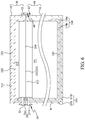
- FIG. 6 is a sectional view taken along line B-B of FIG. 1 ;
- FIG. 7 is a sectional view showing the cover portion is pivotally turnable relative to the body portion of the cooler box of the present invention.
- FIG. 8 is an enlarged, fragmentary view showing a fastening structure mounted to the body portion and the cover portion of the cooler box of the present invention.
- FIG. 9 is a flowchart showing the steps included in a cooler box manufacturing method according to a preferred embodiment of the present invention.
- FIGS. 10A and 10B are pictorial descriptions of an outer shell forming step included in the method of the present invention shown in FIG. 9 ;
- FIG. 11 is a pictorial description of a storage compartment forming step included in the method of the present invention shown in FIG. 9 ;
- FIG. 12 is a pictorial description of a body portion forming step included in the method of the present invention shown in FIG. 9 ;
- FIGS. 13A and 13B are pictorial descriptions of a cover outer shell forming step included in the method of the present invention shown in FIG. 9 ;
- FIG. 14 is a pictorial description of a cover storage compartment forming step included in the method of the present invention shown in FIG. 9 ;
- FIG. 15 is a pictorial description of a cover portion forming step included in the method of the present invention shown in FIG. 9 ;
- FIG. 16 is a pictorial description of a cooler box forming step included in the method of the present invention shown in FIG. 9 .
- a cooler box includes a body portion 10 , a cover portion 20 , a hinge structure 30 , and a fastening structure 40 .
- the body portion 10 is formed of a three-dimensional storage compartment 11 and a binding frame 12 assembled to an upper end of the storage compartment 11 .
- the storage compartment 11 internally defines a storage space 111 , which is communicable with a storage opening 112 formed at the upper end of the storage compartment 11 .
- the storage compartment 11 has an outermost layer in the form of a three-dimensional outer shell 113 , and an innermost layer being an inner shell 114 having a three-dimensional configuration smaller than the outer shell 113 .
- it is the inner shell 114 that internally defines the storage space 111 .
- the outer shell 113 can be made of an acrylonitrile butadiene styrene (ABS) resin exclusively or made of a polycarbonate (PC) resin exclusively.
- the outer shell 113 can be otherwise made of an ABS resin and a PC resin.
- the outer shell 113 has an outermost side formed of the PC resin and an innermost side formed of the ABS resin.
- the inner shell 114 can be made of a polypropylene (PP) resin or a polyethylene (PE) resin.
- the outer shell 113 includes a continuous outer wall portion 113 a in the form of a hollow column, and an outer base portion 113 b integrally formed with and located at a lower side of the outer wall portion 113 a ; and the inner shell 114 includes a continuous inner wall portion 114 a having dimensions smaller than the outer wall portion 113 a and an inner base portion 114 b integrally formed with and located at a lower side of the inner wall portion 114 a .
- the inner shell 114 is fitted in the outer shell 113 with a space remained between the inner wall portion 114 a and the outer wall portion 113 a and between the inner base portion 114 b and the outer base portion 113 b , such that an insulation layer 115 can be disposed between the outer shell 113 and the inner shell 114 for temperature loss protection. Therefore, the storage space 111 is enclosed by, from an inner side to an outer side, the inner shell 114 , the insulation layer 115 and the outer shell 113 . As can be seen in FIG.
- a thickness of the outer wall portion 113 a , a thickness of the inner wall portion 114 a and a thickness of the insulation layer 115 together define an assembled thickness 116 (see FIG. 2 ) of the storage compartment 11 .
- the binding frame 12 is made of an elastic material, and includes a connecting loop portion 121 defining a central opening 122 and an outer and an inner clamping wall portion 123 substantially parallelly extending along two opposite lateral edges of the connecting loop portion 121 , such that the connecting loop portion 121 and the two clamping wall portions 123 together define a binding space 124 in between them. More specifically, the inner and the outer clamping wall portion 123 together define a bound thickness 125 between them, and the bound thickness 125 is smaller than or equal to the assembled thickness 116 .
- the binding frame 12 can be made of a PP resin or a PE resin.
- the selected PE resin is preferably a high-density polyethylene (HDPE) or a linear low-density polyethylene (LLDPE) resin.
- the binding frame 12 is assembled to the upper end of the storage compartment 11 with the connecting loop portion 121 located around the storage opening 112 , such that the central opening 122 of the binding frame 12 is communicable with the storage space 111 via the storage opening 112 .
- the outer wall portion 113 a of the outer shell 113 , the insulation layer 115 and the inner wall portion 114 a of the inner shell 114 respectively have a length adjacent to their upper ends being received in the binding space 124 of the binding frame 12 , and the upper ends of the outer wall portion 113 a of the outer shell 113 , the insulation layer 115 and the inner wall portion 114 a of the inner shell 114 closer to the storage opening 112 all are in contact with the connecting loop portion 121 of the binding frame 12 .
- the inner and the outer clamping wall portion 123 of the binding frame 12 tend to deform and separate from each other while generating an inward clamping force against the outer wall portion 113 a , the inner wall portion 114 a and the insulation layer 115 , bringing the outer shell 113 , the inner shell 114 , the connecting loop portion 121 and the inner and outer clamping wall portions 123 to together constitute an enclosed space R, in which the insulation layer 115 is fixedly held.
- the cover portion 20 is configured as a three-dimensional structure having a size smaller than that of the body portion 10 and is located on a top of the body portion 10 .
- the cover portion 20 includes a three-dimensional cover storage compartment 21 and a cover binding frame 22 assembled to a lower end of the cover storage compartment 21 .
- the cover storage compartment 21 is structurally similar to the storage compartment 11 of the body portion 10 and is formed at the lower end with a cover storage opening 214 and internally defines a cover storage space 215 .
- the cover storage compartment 21 includes a cover outer shell 211 and a cover inner shell 212 , which are similar to the outer shell 113 and the inner shell 114 of the storage compartment 11 , respectively, in terms of the forming materials and the structures thereof.
- a cover insulation layer 213 is disposed between the cover outer shell 211 and the cover inner shell 212 to provide the same function as the insulation layer 115 .
- the cover binding frame 22 is structurally similar to the binding frame 12 of the body portion 10 for assembling to the lower end of the cover storage compartment 21 , and includes an inner and an outer cover clamping wall portion 221 for together clamping on the cover outer shell 211 , the cover inner shell 212 and the cover insulation layer 213 .
- the cover binding frame 22 also defines a cover central opening 222 , which is communicable with the cover storage space 215 defined in the cover storage compartment 21 via the cover storage opening 214 of the cover storage compartment 21 .
- the hinge structure 30 is mounted to between the body portion 10 and the cover portion 20 , and includes two hinge members 31 and a plurality of insertion pins 32 .
- Each of the hinge members 31 includes two structurally identical leaves 311 .
- the leaves 311 respectively have a part forming a pivotal portion 311 a and another part forming a perforated plate portion 311 b .
- the pivotal portion 311 a of one of the two leaves 311 is rotatably connected to the pivotal portion 311 a of the other leaf 311 , such that the perforated plate portions 311 b of the two leaves 311 are pivotally turnable relative to each other via the rotatable connection of the two pivotal portions 311 a to selectively move toward or away from each other.
- One of the two leaves 311 of each hinge member 31 is located on a rear side of the body portion 10 with a part of the insertion pins 32 extended through the perforated plate portion 311 b of the leaf 311 , such that the insertion pins 32 further sequentially extend through the outer clamping wall portion 123 of the binding frame 12 , the outer wall portion 113 a of the outer shell 113 , the insulation layer 115 , the inner wall portion 114 a of the inner shell 114 , and the inner clamping wall portion 123 of the binding frame 12 .
- the outer shell 113 , the insulation layer 115 , the inner shell 114 and the binding frame 12 are tightly bound together without being easily separated from one another, and the leaf 311 is fixedly held to the rear side of the body portion 10 by the insertion pins 32 .
- the other leaf 311 of each hinge member 31 is located on a rear side of the cover portion 20 with the other part of the insertion pins 32 extended through the perforated plate portion 311 b of the other leaf 311 , such that the other insertion pins 32 further sequentially extend through the outer cover clamping wall portion 221 of the cover binding frame 22 , the cover outer shell 211 , the cover insulation layer 213 , the cover inner shell 212 , and the inner cover clamping wall portion 221 of the cover binding frame 22 . In this manner, the other leaf 311 of each hinge member 31 is fixedly held to the rear side of the cover portion 20 by the other insertion pins 32 . Further, as can be seen in FIG.
- the cover portion 20 connected to the body portion 10 can be pivotally turned relative to the body portion 10 to selectively close or expose the storage opening 112 of the body portion 10 .
- the fastening structure 40 is located between the body portion 10 and the cover portion 20 and includes at least one first fastening member 41 and one second fastening member 42 .
- the first fastening member 41 is selectively connectable to or releasable from the second fastening member 42 .
- the first fastening member 41 is located on a front side of the body portion 10 and fixedly connected to the outer clamping wall portion 123 of the binding frame 12
- the second fastening member 42 is located on a front side of the cover portion 20 and fixedly connected to the outer cover clamping wall portion 221 .
- the cover portion 20 When the first fastening member 41 is fastened to the second fastening member 42 , the cover portion 20 is stopped from being turned via the hinge structure 30 to thereby continuously close the storage opening 112 of the body portion 10 , and the storage space 111 is in a closed state and not communicable with an external environment. On the other hand, when the first fastening member 41 is released from the second fastening member 42 , the cover portion 20 can be turned open via the hinge structure 30 and the storage space 111 is in an open state and communicable with the external environment. With these arrangements, the fastening structure 40 is able to restrict the cover portion 20 to a closed position to continuously cover the storage opening 112 .
- the present invention also provides a method for manufacturing the above described cooler box. Please refer to FIGS. 9, 10A and 10B .
- a panel 113 c is installed in a vacuum forming machine 50 and a heating mechanism 51 mounted in the vacuum forming machine 50 starts heating, so that the panel 113 c is heated by the heating mechanism 51 and becomes softened and deformable in a heating environment of 150-200° C.
- the softened panel 113 c is moved in the vacuum forming machine 50 toward a first forming mold 52 mounted in the vacuum forming machine 50 and subjected to a vacuum suction operation, such that the softened panel 113 c is attached to an outer surface of the first forming mold 52 under a vacuum suction force and forms an outer shell 113 .
- the panel 113 c can be made of an ABS resin exclusively, or can be made of an ABS resin and a PC resin.
- a storage compartment forming step S 2 starts, in which an insulation layer 115 is positioned on an inner side of the outer shell 113 and an inner shell 114 is further positioned into the outer shell 113 , so that the insulation layer 115 is located between the outer shell 113 and the inner shell 114 and a storage compartment 11 having a storage space 111 and a storage opening 112 is formed.
- a body portion forming step S 3 is performed, in which, as shown in FIG.
- a binding frame 12 is assembled to an upper end of the storage compartment 11 , so that an inner and an outer clamping wall portion 123 of the binding frame 12 together inwardly clamp on an outer wall portion 113 a of the outer shell 113 , an inner wall portion 114 a of the inner shell 114 and the insulation layer 115 with a connecting loop portion 121 of the binding frame 12 being located around the storage opening 112 , bringing the storage compartment 11 and the binding frame 12 to assemble to each other and together form a body portion 10 for a cooler box.
- a cover outer shell forming step S 4 can be performed when the outer shell forming step S 1 is being performed.
- a cover panel 211 a having the same material as the panel 113 c is installed in a vacuum forming machine 50 , and a heating mechanism 51 mounted in the vacuum forming machine 50 starts heating to a temperature ranged between 150 and 200° C., so that the cover panel 211 a is heated and becomes softened and deformable.
- the softened cover panel 211 a is moved in the vacuum forming machine 50 toward a second forming mold 53 , which is mounted in the vacuum forming machine 50 and different from the first forming mold 52 in size.
- the softened cover panel 211 a is then subjected to a vacuum suction operation to be attached to an outer surface of the second forming mold 53 under a vacuum suction force and forms a cover outer shell 211 .
- the cover panel 211 a can be made of an ABS resin exclusively or be made of an ABS resin and a PC resin.
- a cover storage compartment forming step S 5 starts, in which a cover insulation layer 213 and a cover inner shell 212 are sequentially positioned on an inner side of the cover outer shell 211 , so that the cover insulation layer 213 is located between the cover outer shell 211 and the cover inner shell 212 and a cover storage compartment 21 having a cover storage space 215 and a cover storage opening 214 is formed. Then, a cover portion forming step S 6 is performed, in which, as shown in FIG.
- a cover binding frame 22 is assembled to the cover storage compartment 21 , so that an inner and an outer cover clamping wall portion 221 of the cover binding frame 22 together inwardly clamp on the cover outer shell 211 , the cover inner shell 212 and the cover insulation layer 213 , bringing the cover storage compartment 21 and the cover binding frame 22 to assemble to each other and together form a cover portion 20 for a cooler box.
- a cooler box forming step S 7 is performed, in which the cover portion 20 is pivotally turnably connected to the body portion 10 via a hinge structure 30 to form a cooler box. More specifically, in the step 7 , each of two hinge members 31 of the hinge structure 30 is fixedly connected to the binding frame 12 and the cover binding frame 22 by extending a plurality of insertion pins 32 through one of two leaves 311 of the hinge member 31 sequentially into the outer clamping wall portion 123 of the binding frame 12 , the outer shell 113 , the insulation layer 115 , the inner shell 114 and the inner clamping wall portion 123 of the binding frame 12 , and extending another plurality of insertion pins 32 through the other leaf 311 of the hinge member 31 sequentially into the outer cover clamping wall portion 221 , the cover outer shell 211 , the cover insulation layer 213 , the cover inner shell 212 and the inner cover clamping wall portion 221 of the cover binding frame 22 .
Landscapes
- Engineering & Computer Science (AREA)
- Mechanical Engineering (AREA)
- Packages (AREA)
Abstract
Description
Claims (7)
Priority Applications (1)
| Application Number | Priority Date | Filing Date | Title |
|---|---|---|---|
| US16/036,098 US10696467B2 (en) | 2018-07-16 | 2018-07-16 | Cooler box and manufacturing method thereof |
Applications Claiming Priority (1)
| Application Number | Priority Date | Filing Date | Title |
|---|---|---|---|
| US16/036,098 US10696467B2 (en) | 2018-07-16 | 2018-07-16 | Cooler box and manufacturing method thereof |
Publications (2)
| Publication Number | Publication Date |
|---|---|
| US20200017277A1 US20200017277A1 (en) | 2020-01-16 |
| US10696467B2 true US10696467B2 (en) | 2020-06-30 |
Family
ID=69139949
Family Applications (1)
| Application Number | Title | Priority Date | Filing Date |
|---|---|---|---|
| US16/036,098 Active 2038-10-22 US10696467B2 (en) | 2018-07-16 | 2018-07-16 | Cooler box and manufacturing method thereof |
Country Status (1)
| Country | Link |
|---|---|
| US (1) | US10696467B2 (en) |
Cited By (3)
| Publication number | Priority date | Publication date | Assignee | Title |
|---|---|---|---|---|
| US20210408865A1 (en) * | 2020-06-27 | 2021-12-30 | James Michael Wheeler | Portable Housing For Use With Portable Electric Generators |
| US20240142156A1 (en) * | 2018-04-05 | 2024-05-02 | Lg Electronics Inc. | Refrigerator |
| US12378058B2 (en) | 2015-11-25 | 2025-08-05 | Yeti Coolers, Llc | US CIP: insulating container having vacuum insulated panels and method |
Families Citing this family (8)
| Publication number | Priority date | Publication date | Assignee | Title |
|---|---|---|---|---|
| US11118830B2 (en) * | 2019-02-09 | 2021-09-14 | Brian Keith McKinnon | Cooler system |
| US11555644B2 (en) * | 2019-05-20 | 2023-01-17 | Wool Street LLC | Insulated cooler system |
| USD958202S1 (en) * | 2020-05-06 | 2022-07-19 | Foshan Alpicool Electric Appliance Co., LTD. | Car fridge |
| USD959508S1 (en) * | 2020-05-11 | 2022-08-02 | Foshan Alpicool Electric Appliance Co., LTD. | Car fridge |
| CN112129020A (en) * | 2020-09-15 | 2020-12-25 | 长虹美菱股份有限公司 | A kind of multifunctional outer barrel, box body and box body installation method |
| CN112082319B (en) * | 2020-09-17 | 2022-06-07 | 长虹美菱股份有限公司 | Refrigerator body decorating part, refrigerator body and refrigerator body mounting method |
| CN112097460A (en) * | 2020-09-24 | 2020-12-18 | 长虹美菱股份有限公司 | Inner barrel of refrigerator body, refrigerator body and refrigerator body installation method |
| ES2911974B2 (en) * | 2020-11-20 | 2022-09-23 | Palec Ecologico S L | ISOTHERMAL BOX FOR STORING AND TRANSPORTING PRODUCTS |
Citations (26)
| Publication number | Priority date | Publication date | Assignee | Title |
|---|---|---|---|---|
| US2347192A (en) * | 1942-04-23 | 1944-04-25 | Letcher O Grice | Trunk locker |
| US2743029A (en) * | 1950-05-05 | 1956-04-24 | Skydyne Inc | Shipping case or the like |
| US2980285A (en) * | 1957-09-10 | 1961-04-18 | Skydyne Inc | Case construction |
| US3561634A (en) * | 1968-09-11 | 1971-02-09 | Impetus Inc | Shipping container |
| US3730309A (en) * | 1970-07-30 | 1973-05-01 | Hamann Rox Lederwaren | Suitcase |
| US3989157A (en) * | 1974-05-29 | 1976-11-02 | Lunn Laminates, Inc. | Container assembly |
| US4271975A (en) * | 1979-08-23 | 1981-06-09 | The Boeing Company | Lightweight cargo container and fittings |
| US4319629A (en) * | 1978-04-28 | 1982-03-16 | Shimano Industrial Company Limited | Constant temperature box |
| US4558797A (en) * | 1983-12-27 | 1985-12-17 | Quest Product Development, Ltd. | Storage unit module |
| US4998636A (en) * | 1989-06-30 | 1991-03-12 | Hardigg Industries, Inc. | Electronic rack and mounting frame |
| US5000301A (en) * | 1982-09-14 | 1991-03-19 | 501 Louis Vuitton Malletier | Suitcase |
| US5050387A (en) * | 1988-03-02 | 1991-09-24 | Pallet-Cooler Kb | Method and container for storing and distribution of foodstuffs |
| US5429259A (en) * | 1994-06-17 | 1995-07-04 | Robin; Raymond S. | Interlocking crating system |
| US5435142A (en) * | 1993-12-13 | 1995-07-25 | In Vitro Technologies, Inc. | Method of and apparatus for packaging temperature sensitive materials for transportation |
| US5562228A (en) * | 1994-06-06 | 1996-10-08 | Ericson; John C. | Collapsible cooler apparatus |
| US5924302A (en) * | 1997-03-27 | 1999-07-20 | Foremost In Packaging Systems, Inc. | Insulated shipping container |
| US5979693A (en) * | 1997-12-29 | 1999-11-09 | Bane, Iii; William W. | Panel for shipping containers |
| US5996828A (en) * | 1998-10-09 | 1999-12-07 | Cheyn; Ruey Chyuan | Corner assembly for a box |
| US20040174106A1 (en) * | 2001-06-04 | 2004-09-09 | Kazutaka Uekado | Insulated box body, refrigerator having the box body, and method of recycling materials for insulated box body |
| US7422143B2 (en) * | 2002-10-23 | 2008-09-09 | Minnesota Thermal Science, Llc | Container having passive controlled temperature interior |
| US20090032530A1 (en) * | 2007-07-30 | 2009-02-05 | Pacific Container Network, Inc. | Joint structure for portable work and storage container |
| US7908870B2 (en) * | 2007-05-04 | 2011-03-22 | Entropy Solutions, Inc. | Package having phase change materials and method of use in transport of temperature sensitive payload |
| US8196758B2 (en) * | 2010-06-17 | 2012-06-12 | Lee Yung-Yu | Frame assembly |
| US8689992B2 (en) * | 2011-02-03 | 2014-04-08 | Suncast Technologies, Llc | Wood and resin deck box |
| US20180186511A1 (en) * | 2017-01-02 | 2018-07-05 | Lyno Lewis Sullivan | Modular Storage Container System |
| US20190367263A1 (en) * | 2018-06-04 | 2019-12-05 | Jan Chabot | Assembly System For Customizable Containers |
-
2018
- 2018-07-16 US US16/036,098 patent/US10696467B2/en active Active
Patent Citations (26)
| Publication number | Priority date | Publication date | Assignee | Title |
|---|---|---|---|---|
| US2347192A (en) * | 1942-04-23 | 1944-04-25 | Letcher O Grice | Trunk locker |
| US2743029A (en) * | 1950-05-05 | 1956-04-24 | Skydyne Inc | Shipping case or the like |
| US2980285A (en) * | 1957-09-10 | 1961-04-18 | Skydyne Inc | Case construction |
| US3561634A (en) * | 1968-09-11 | 1971-02-09 | Impetus Inc | Shipping container |
| US3730309A (en) * | 1970-07-30 | 1973-05-01 | Hamann Rox Lederwaren | Suitcase |
| US3989157A (en) * | 1974-05-29 | 1976-11-02 | Lunn Laminates, Inc. | Container assembly |
| US4319629A (en) * | 1978-04-28 | 1982-03-16 | Shimano Industrial Company Limited | Constant temperature box |
| US4271975A (en) * | 1979-08-23 | 1981-06-09 | The Boeing Company | Lightweight cargo container and fittings |
| US5000301A (en) * | 1982-09-14 | 1991-03-19 | 501 Louis Vuitton Malletier | Suitcase |
| US4558797A (en) * | 1983-12-27 | 1985-12-17 | Quest Product Development, Ltd. | Storage unit module |
| US5050387A (en) * | 1988-03-02 | 1991-09-24 | Pallet-Cooler Kb | Method and container for storing and distribution of foodstuffs |
| US4998636A (en) * | 1989-06-30 | 1991-03-12 | Hardigg Industries, Inc. | Electronic rack and mounting frame |
| US5435142A (en) * | 1993-12-13 | 1995-07-25 | In Vitro Technologies, Inc. | Method of and apparatus for packaging temperature sensitive materials for transportation |
| US5562228A (en) * | 1994-06-06 | 1996-10-08 | Ericson; John C. | Collapsible cooler apparatus |
| US5429259A (en) * | 1994-06-17 | 1995-07-04 | Robin; Raymond S. | Interlocking crating system |
| US5924302A (en) * | 1997-03-27 | 1999-07-20 | Foremost In Packaging Systems, Inc. | Insulated shipping container |
| US5979693A (en) * | 1997-12-29 | 1999-11-09 | Bane, Iii; William W. | Panel for shipping containers |
| US5996828A (en) * | 1998-10-09 | 1999-12-07 | Cheyn; Ruey Chyuan | Corner assembly for a box |
| US20040174106A1 (en) * | 2001-06-04 | 2004-09-09 | Kazutaka Uekado | Insulated box body, refrigerator having the box body, and method of recycling materials for insulated box body |
| US7422143B2 (en) * | 2002-10-23 | 2008-09-09 | Minnesota Thermal Science, Llc | Container having passive controlled temperature interior |
| US7908870B2 (en) * | 2007-05-04 | 2011-03-22 | Entropy Solutions, Inc. | Package having phase change materials and method of use in transport of temperature sensitive payload |
| US20090032530A1 (en) * | 2007-07-30 | 2009-02-05 | Pacific Container Network, Inc. | Joint structure for portable work and storage container |
| US8196758B2 (en) * | 2010-06-17 | 2012-06-12 | Lee Yung-Yu | Frame assembly |
| US8689992B2 (en) * | 2011-02-03 | 2014-04-08 | Suncast Technologies, Llc | Wood and resin deck box |
| US20180186511A1 (en) * | 2017-01-02 | 2018-07-05 | Lyno Lewis Sullivan | Modular Storage Container System |
| US20190367263A1 (en) * | 2018-06-04 | 2019-12-05 | Jan Chabot | Assembly System For Customizable Containers |
Cited By (4)
| Publication number | Priority date | Publication date | Assignee | Title |
|---|---|---|---|---|
| US12378058B2 (en) | 2015-11-25 | 2025-08-05 | Yeti Coolers, Llc | US CIP: insulating container having vacuum insulated panels and method |
| US20240142156A1 (en) * | 2018-04-05 | 2024-05-02 | Lg Electronics Inc. | Refrigerator |
| US20210408865A1 (en) * | 2020-06-27 | 2021-12-30 | James Michael Wheeler | Portable Housing For Use With Portable Electric Generators |
| US11621603B2 (en) * | 2020-06-27 | 2023-04-04 | James Michael Wheeler | Portable housing for use with portable electric generators |
Also Published As
| Publication number | Publication date |
|---|---|
| US20200017277A1 (en) | 2020-01-16 |
Similar Documents
| Publication | Publication Date | Title |
|---|---|---|
| US10696467B2 (en) | Cooler box and manufacturing method thereof | |
| US10676235B1 (en) | Folding box | |
| US6415915B1 (en) | Eyeglass case stand | |
| WO2002085725A1 (en) | Storage container | |
| CN117412680A (en) | Snuff container | |
| USD529800S1 (en) | Round container lid | |
| JP6963404B2 (en) | File | |
| US9292050B2 (en) | Detachable electronic device with cover portion | |
| US6905450B2 (en) | Clam shell container with cover and inner tray | |
| US3958676A (en) | Luggage case with soft sided exterior | |
| USD1000480S1 (en) | Portable cooler/ storage container | |
| JP4341189B2 (en) | Foldable assembly container | |
| JP2020132256A (en) | Household tissue paper storage container | |
| JP2007091277A (en) | Foldable container | |
| JP3692470B2 (en) | Packaging container | |
| CN222934308U (en) | Stacked clay box | |
| KR102434983B1 (en) | Container for | |
| JP3214955U (en) | suitcase | |
| JP5309942B2 (en) | Package tray | |
| KR200381968Y1 (en) | Package for Mounting Speaker | |
| JP3589370B2 (en) | Folding container | |
| JP5970504B2 (en) | Round back book type case | |
| KR200339407Y1 (en) | Foldable box possiblly having higher side wall plates | |
| TWI729436B (en) | Improved structure of storage box (29) | |
| TWI734137B (en) | Improved structure of storage box (28) |
Legal Events
| Date | Code | Title | Description |
|---|---|---|---|
| AS | Assignment |
Owner name: FTI GROUP (HOLDING) COMPANY LIMITED, CAYMAN ISLAND Free format text: ASSIGNMENT OF ASSIGNORS INTEREST;ASSIGNOR:MOON, JERRY;REEL/FRAME:046359/0005 Effective date: 20180710 Owner name: FTI GROUP (HOLDING) COMPANY LIMITED, CAYMAN ISLANDS Free format text: ASSIGNMENT OF ASSIGNORS INTEREST;ASSIGNOR:MOON, JERRY;REEL/FRAME:046359/0005 Effective date: 20180710 |
|
| FEPP | Fee payment procedure |
Free format text: ENTITY STATUS SET TO UNDISCOUNTED (ORIGINAL EVENT CODE: BIG.); ENTITY STATUS OF PATENT OWNER: SMALL ENTITY |
|
| FEPP | Fee payment procedure |
Free format text: ENTITY STATUS SET TO SMALL (ORIGINAL EVENT CODE: SMAL); ENTITY STATUS OF PATENT OWNER: SMALL ENTITY |
|
| STPP | Information on status: patent application and granting procedure in general |
Free format text: NON FINAL ACTION MAILED |
|
| STPP | Information on status: patent application and granting procedure in general |
Free format text: RESPONSE TO NON-FINAL OFFICE ACTION ENTERED AND FORWARDED TO EXAMINER |
|
| STPP | Information on status: patent application and granting procedure in general |
Free format text: PUBLICATIONS -- ISSUE FEE PAYMENT RECEIVED |
|
| STCF | Information on status: patent grant |
Free format text: PATENTED CASE |
|
| MAFP | Maintenance fee payment |
Free format text: PAYMENT OF MAINTENANCE FEE, 4TH YR, SMALL ENTITY (ORIGINAL EVENT CODE: M2551); ENTITY STATUS OF PATENT OWNER: SMALL ENTITY Year of fee payment: 4 |