EP0833552B1 - Improved electronic rack and mounting frame - Google Patents
Improved electronic rack and mounting frame Download PDFInfo
- Publication number
- EP0833552B1 EP0833552B1 EP97307540A EP97307540A EP0833552B1 EP 0833552 B1 EP0833552 B1 EP 0833552B1 EP 97307540 A EP97307540 A EP 97307540A EP 97307540 A EP97307540 A EP 97307540A EP 0833552 B1 EP0833552 B1 EP 0833552B1
- Authority
- EP
- European Patent Office
- Prior art keywords
- members
- splice
- frame
- electronics rack
- mounting frame
- Prior art date
- Legal status (The legal status is an assumption and is not a legal conclusion. Google has not performed a legal analysis and makes no representation as to the accuracy of the status listed.)
- Expired - Lifetime
Links
- 239000007787 solid Substances 0.000 claims description 4
- 229910052782 aluminium Inorganic materials 0.000 claims description 3
- XAGFODPZIPBFFR-UHFFFAOYSA-N aluminium Chemical compound [Al] XAGFODPZIPBFFR-UHFFFAOYSA-N 0.000 claims description 3
- 239000004411 aluminium Substances 0.000 claims description 2
- 239000000463 material Substances 0.000 claims description 2
- 230000035939 shock Effects 0.000 description 8
- 238000004519 manufacturing process Methods 0.000 description 5
- 230000008901 benefit Effects 0.000 description 3
- 238000010276 construction Methods 0.000 description 3
- 238000000034 method Methods 0.000 description 3
- 238000003780 insertion Methods 0.000 description 2
- 230000037431 insertion Effects 0.000 description 2
- 238000003754 machining Methods 0.000 description 2
- 230000008569 process Effects 0.000 description 2
- 238000003860 storage Methods 0.000 description 2
- 238000003466 welding Methods 0.000 description 2
- 239000004698 Polyethylene Substances 0.000 description 1
- 230000009471 action Effects 0.000 description 1
- 230000007123 defense Effects 0.000 description 1
- 230000007812 deficiency Effects 0.000 description 1
- 238000005553 drilling Methods 0.000 description 1
- 230000006872 improvement Effects 0.000 description 1
- 229910052751 metal Inorganic materials 0.000 description 1
- 239000002184 metal Substances 0.000 description 1
- 238000012986 modification Methods 0.000 description 1
- 230000004048 modification Effects 0.000 description 1
- -1 polyethylene Polymers 0.000 description 1
- 229920000573 polyethylene Polymers 0.000 description 1
- 238000010008 shearing Methods 0.000 description 1
- WFKWXMTUELFFGS-UHFFFAOYSA-N tungsten Chemical compound [W] WFKWXMTUELFFGS-UHFFFAOYSA-N 0.000 description 1
- 229910052721 tungsten Inorganic materials 0.000 description 1
- 239000010937 tungsten Substances 0.000 description 1
Images

Classifications
-
- H—ELECTRICITY
- H05—ELECTRIC TECHNIQUES NOT OTHERWISE PROVIDED FOR
- H05K—PRINTED CIRCUITS; CASINGS OR CONSTRUCTIONAL DETAILS OF ELECTRIC APPARATUS; MANUFACTURE OF ASSEMBLAGES OF ELECTRICAL COMPONENTS
- H05K7/00—Constructional details common to different types of electric apparatus
- H05K7/18—Construction of rack or frame
- H05K7/183—Construction of rack or frame support rails therefor
Definitions
- a further disadvantage of a welded rack system is the storage space required to keep finished racks in stock in order to fill orders promptly.
- a more recent prior art electronic rack mounting frame is disclosed in US-A-4 998 636 and comprises a plurality of vertical and horizontal frame members interconnected by internal splice members having horizontal and vertical leg portions joined at right angles.
- a separate external splice member can be used to attach a side frame member to the internal splice member and vertical and horizontal frame members.
- the only force holding the shape of the unit is the frictional force created by the clamping action of the threaded fastener; there is no structural resistance against movement.
- moving the frame in shear against only the frictional force created by the clamping force of the fastener is orders of magnitude easier than moving the parts by shearing the fasteners. Creating a rombus from the intended rectangle is therefore relatively easy in the prior art.
- a further object of the present invention is to provide a rack and mounting frame having frame members that can be assembled quickly and easily in accordance with precise dimensional tolerance and that can be disassembled if desired.
- an electronics rack and mounting frame comprising a plurality of horizontal frame members, each of the horizontal frame members having two ends and having a pinhole therethrough on both ends thereof, a plurality of vertical framemembers, each of the vertical frame members having two ends and having a pinhole therethrough on both ends thereof, a plurality of internal splice members, each of the splice members having leg portions engageable within one end of a horizontal frame member and one end of a vertical frame member, the leg portions including pin holes alignable with the pinhole in each of the horizontal frame members and the vertical frame members, a plurality of pins pressed into the pinholes when the pinholes are aligned, the pins fastening the horizontal frame member and the vertical frame member to the splice member, characterised in that each of the splice members further includes an integrally formed central portion, providing a first planar abutment for limiting the engagement of the splice member with the horizontal frame member and
- the electronics rack and mounting frame further comprises a plurality of side members, each of the side members having two ends and having a pin hole therethrough on both ends thereof, and each of the splice members being engageable with one side member.
- the central portion may have a third planar abutment for limiting engagement of the splice member with the side member, and the third planar abutment is substantially perpendicular to the first and second planar abutments.
- the horizontal frame member, vertical frame member and side frame member extend substantially perpendicularly from one another when engaged with the splice member.
- the horizontal, vertical and side frame members are connected by one-piece splice members
- the central portion includes an exterior surface which is substantially co-planar with an exterior surface of the horizontal frame member, an exterior surface of the vertical frame member and an exterior surface of the side member when the horizontal frame member abuts the first planar abutment, the vertical frame member abuts the second planar abutment and the side member abuts the third planar abutment.
- the central portion may define a chamfered profile and may provide a shoulder portion for attaching the side frame member.
- the horizontal and vertical frame members may have axial receptacles formed in the two ends and the leg portions of each splice member extend from the central portion with the leg portions being oriented substantially perpendicularly from one another and dimensioned to be accepted into the axial receptacles of the horizontal and vertical frame members.
- the pins connecting the horizontal and vertical frame members to the splice members are one of a spring pin, a roll pin and a solid pin.
- the splice members may detachably secure the distal ends of the vertical and horizontal frame members to form a front frame panel and a rear frame panel with the side frame members detachably secured to the splice members to connect the front and rear frame panels.
- the vertical and horizontal frame members may be made hollow throughout their entire lengths from an extrudable, high tensile strength aluminium material.
- the vertical frame members of the front frame panel may have a plurality of threaded mounting holes in the electronic equipment module that is to be mounted to the frame.
- the holes and spacings are made up of units of three holes with 1.59cm, 1.59cm and 1.27cm (5/8 inch, 5/8 inch and 1/2 inch) between them respectively according to standard EIA-310-D.
- the hollow vertical and horizontal frame members may have a substantially rectangular cross-section such that the frame members are defined by a front and a read wall and a pair of side walls.
- a suitable rack and mounting frame may be produced using eight splice members, four vertical frame members, four horizontal frame members and four side frame members wherein the splice members are identical as are the vertical and horizontal frame members.
- the rack and mounting frame according to the present invention may include additional features such as diagonally-extending frame members detachably secured to the side frame members.
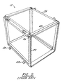
- FIGURE 1 is a representation of a prior art shipping and storage container 10 which contains a rack and mounting frame 12 for mounting electronic equipment thereon.
- the electronic equipment 14 is provided with a bezeled front panel 16 in which holes 18 are disposed for securing the equipment 14 to the frame 12.
- the rack and mounting frame 12 is constructed from a plurality of vertical and horizontal members 20 and 22 and side frame members 24, all of which are preferably made from extruded, high tensile strength aluminum.
- the ends of each vertical 20, horizontal 22 and side frame members 24 are affixed to one another at right angles via an L-shaped internal splice member 26 and an external splice (not shown) attached to one side of said internal splice member 26.
- the side frame members 24 are provided with a pair of rubber shock mounts 28 which are disposed at a 45° angle to the vertical members, in spaced relation, on each side frame member 24, running in the fore-to-aft direction.
- the shock mounts 28 are dimensional so that they engage brackets (not shown) mounted inside the container 10, thereby suspending the frame 12 within the hollow interior thereof.
- the rack system 30, is shown in FIGURE 3 and is designed to overcome the deficiencies in the prior art rack system described above.
- Rack system 30, like the prior art device of FIGURE 2, employs a rectangular, parallelpiped frame structure comprising vertical and horizontal frame members 32 and 34 and side frame members 36.
- the side frame members 36 are provided with a pair of shock mounts 38, similar to those disclosed in connection with the prior art device shown in FIGURE 2, for mounting the rack frame 30 within the hollow interior of a transport container.
- the vertical and horizontal frame members 32 and 34 that make up the front and back frame panels 40 and 42 of the rack system 30 are, preferably, extruded tubing most preferably having a rectangular cross-section with hollow interior 44 as illustrated in FIGURE 4.
- the tube may be hollow throughout or merely may have a receptacle end portion and otherwise be solid or otherwise obstructed.
- both the horizontal and vertical frame members 32 and 34 are identical as far as their cross-section and end configuration are concerned, the vertical frame members 32 are provided with a standard pattern of threaded mounting holes 46. This standard pattern is dictated under EIA-310-D for vertical members whereas it is not necessary for the horizontal members to include these holes.
- the holes 46 extend the length of the front and rear walls 48 and 50 of frame members 32 for securing the front bezel panel of an electronic equipment module to the frame.
- the vertical frame members are employed to secure equipment. It is possible, however, to employ the horizontal members alone or in combination with the vertical members. As one of skill in the art will appreciate, however, horizontal members with no threaded holes and only pin holes are preferable, due to the cost of adding the unnecessary drilling and threading.
- front and back walls of the vertical frame member are most preferably 0.64cm (0.25”) thick to provide sufficient screw thread length whereas the side walls are 0.203cm (0.080”) thick to minimize weight of the completed rack.
- each L-shaped internal splice member 54 comprises a vertical leg portion 56 and a horizontal leg portion 58 which are disposed and integrally joined at right angles by a central portion 60 such that the outer face surfaces 62 of leg portions 56 and 58 form a 45° ° angle with the outer face surfaces 64 of the central portion 60.
- the leg portions 56 and 58 have a rectangular cross-section corresponding approximately to the cross-section of the hollow interiors 44 of the vertical and horizontal frame members 32 and 34.
- the central portion 60 has a somewhat larger cross-section so as to provide abutments 90 and 92 for limiting the depth of insertion of the leg portions 56 and 58 into the vertical and horizontal members 32 and 34.
- the central portions 60 of the L-shaped internal splice member 54 are provided with a shoulder portion 66 which extends outward from a side surface 68 of the central portion 60.
- the shoulder 66 receives and supports one of the ends of side frame members 36.
- the central portion 60 provides a further abutment 93 to limit the engagement of the side frame members 36 with the shoulder 66.
- L-shaped internal splice member 54 is identical for all eight comers so that only one uniquely shaped member must be fabricated for the invention.
- the vertical leg portion 56 of an internal splice member 54 is inserted into the hollow interior 44 of a vertical member 32 and the horizontal leg portion 58 of said splice member 54 is inserted into the hollow interior of a horizontal frame member 34.
- the horizontal, vertical and side frame member When engaged with the splice member 54, the horizontal, vertical and side frame member extend substantive perpendical to one another.
- Each leg portion 56 and 58 is secured to the appropriate frame members 32 and 34 by pairs of spiral pins 63 (FIGURE 5) which are inserted into pin holes 69 in said members 32 and 34 which are aligned with pin holes 67 in said leg portions 56 and 58.
- Spiral spring pins are preferred for their high shear strength, low insertion force, and ability to be inserted automatically.
- Other pins such as roll or solid pins, could also be used.
- the spring pins used are headless and have a length of less than the thickness of a member 32 so that they may be wholly inserted into the pin holes 69 so as to not interfere with holes 46 and/or bezel plate 70 of an electronic equipment module 72 mounted to vertical frame members 32 (FIGURE 6).
- Pins are superior to threaded fasteners in this type of construction because they do not require a clearance fit in one of the members that they engage. The benefit of this is that the pin has an interference fit with both members making shear movements impossible unless the force exerted is beyond the yield strength of the parts or the pins themselves. Where in the prior art, friction was the only defense against these movements. Thus, the ability of the frame of the invention to withstand forces urging it out of square are greatly increased.
- the internal splice members 54 are machined to fit closely in the vertical frame members 32 in the fore-to-aft direction, but need not fit closely in the lateral direction. Said splice members 54 are also machined to provide a close fit inside the horizontal frame members 34 in the fore-to-aft direction, but not in the vertical direction.
- the side members 36 are ready to be assembled.
- the side members 36 are made from metal strips having a flat center portion 74 and outer portions 76 which are bent at 45° angles with respect to the center portion 74.
- the distal ends 78 of each side member 36 are attached at each corner of the front and rear frame portions 40 and 42 by means of the shoulder portion 66.
- the shoulder portion 66 of internal splice member 54 is configured to match the configuration of the side members 36.
- the shoulder portion 66 is provided with a plurality of threaded holes 80 which receive machine screws 82 which are used to hold the side members in engagement with the shoulder portions 66 of the internal splice member 54.
- the thickness of the side frame member corresponds to the depth of the shoulder surface 66 below the outer face surfaces 62 and 64.
- each module 72 is provided with a front bezel panel 70 which is an integral part of the module 72.
- Holes 84 which follow EIA standards, are provided in bezel panel 70 so that said holes 84 align with threaded holes 46 provided along the front side wall 48 of the vertical frame member 32 and on the front of splice-member 54. Screws 86 passing through holes 84 and threaded into holes 46 secure the electronic equipment module 72 to the rack 30. Depending largely upon the weight of the equipment to be secured any number of the threaded holes 46 might be employed.
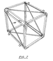
- the construction of the rigid rack frame 30 is sufficient to withstand most impacts and vibrations transmitted through the shock mounts while preventing damage to sensitive electronic equipment secured thereto. However, should it be desirable to further strengthen the frame 30, diagonally-extending brace members 88 can be attached in the pattern illustrated in FIGURE 7.
- the invention is also significantly less expensive to manufacture than prior art units.
- Prior Art Invention 5 unique extruded shapes 3 unique extruded shapes 11 fasteners 7 fasteners 9 screws 3 screws 2 pins 4 pins 16 machine set-ups 11 machine set-ups 16 set-ups 11 set-ups 24 steps 15 steps
Landscapes
- Engineering & Computer Science (AREA)
- Microelectronics & Electronic Packaging (AREA)
- Casings For Electric Apparatus (AREA)
- Structure Of Receivers (AREA)
Description
- Loading and transporting sensitive electronic equipment has presented numerous problems. Typically, such equipment is packed in a suitable shipping container. Even slight impacts or vibrations to the container, however, produce shock forces that may damage precision instruments if they are not properly supported within the container.
- To adequately protect electronic equipment, it is well known to use heavy-duty containers molded from polyethylene for high impact strength. An example of this type of shipping container is disclosed in U.S. Patent No. 4,284,202 issued August 8, 1981 to Barstow Jr. It is also necessary to build into these rugged containers a shock-mitigation system that is capable of protecting the equipment from possible damage during shipping and other rough handling. One known system employs a mounting rack constructed from a plurality of welded vertical and horizontal frame members and shock mounts designed to hold the electronic equipment stationary and to absorb shocks.
- The problem with that prior art electronic rack mounting frame is that the vertical and horizontal members are Gas Shielded Tungsten Arc (TIG) welded together to form an integral frame structure. Although the welded rack frame is sufficiently strong to withstand most impacts and transmit the forces produced thereby from the shock mounts to the electronic equipment without damage, there are difficulties associated with its construction.
- First and foremost is the time required to weld the various frame members together and to correct any distortions caused during the welding process, which adds considerably to the cost of manufacturing the mounting rack. Because of imprecisions in the welding process, it is difficult to maintain alignment of the mounting holes which are used to secure the electronic equipment modules to the rack. A further disadvantage of a welded rack system is the storage space required to keep finished racks in stock in order to fill orders promptly.
- A more recent prior art electronic rack mounting frame is disclosed in US-A-4 998 636 and comprises a plurality of vertical and horizontal frame members interconnected by internal splice members having horizontal and vertical leg portions joined at right angles. A separate external splice member can be used to attach a side frame member to the internal splice member and vertical and horizontal frame members.
- While the electronic rack mounting frame of this Patent is superior to those mentioned above, it has been found that its design requires numerous manufacturing steps and parts in order to properly fabricate the frame. One drawback which has been found is related to the use of threaded fasteners in the patented rack. The front and the rear of the rack are maintained in the desired rectangular shape by threaded fasteners creating a frictional force among parts by passing through a clearance hole in one part and into a threaded hole in another part. Tightening the screw urges the parts together. The problem (shape changing from a rectangle to a rhombus) is a large part due to the clearance hole which is larger in diameter than the fastener passed therethrough. Because of the difference in diametrical size, the only force holding the shape of the unit is the frictional force created by the clamping action of the threaded fastener; there is no structural resistance against movement. As one of skill in the art will readily recognize, moving the frame in shear against only the frictional force created by the clamping force of the fastener is orders of magnitude easier than moving the parts by shearing the fasteners. Creating a rombus from the intended rectangle is therefore relatively easy in the prior art.
- Out of square racks are not favored by the purchasing industries and, therefore, are a drawback to the sales and the reputation of the producer. Remedying the condition is, therefore, desirable and important to the rack mounting frame art.
- It is an object of the present invention to provide a low-cost rack and mounting frame in which fewer parts and less machining is required and where required labor for assembly is reduced compared with rack and mounting frames of the prior art.
- It is a further object of the present invention to provide a rack and mounting frame that is capable of supporting electronic equipment modules inside a container and preventing damage thereto caused by impact and vibration during shipping and handling of the containers.
- A further object of the present invention is to provide a rack and mounting frame having frame members that can be assembled quickly and easily in accordance with precise dimensional tolerance and that can be disassembled if desired.
- It is yet another object of the invention to utilize the shear strength of the fasteners to improve the structural stability of the rack.
- To accomplish these and other objects of the present invention, there is provided according to the present invention an electronics rack and mounting frame comprising a plurality of horizontal frame members, each of the horizontal frame members having two ends and having a pinhole therethrough on both ends thereof, a plurality of vertical framemembers, each of the vertical frame members having two ends and having a pinhole therethrough on both ends thereof, a plurality of internal splice members, each of the splice members having leg portions engageable within one end of a horizontal frame member and one end of a vertical frame member, the leg portions including pin holes alignable with the pinhole in each of the horizontal frame members and the vertical frame members, a plurality of pins pressed into the pinholes when the pinholes are aligned, the pins fastening the horizontal frame member and the vertical frame member to the splice member, characterised in that each of the splice members further includes an integrally formed central portion, providing a first planar abutment for limiting the engagement of the splice member with the horizontal frame member and a second planar abutment for limiting the engagement of the splice member with the vertical frame member.
- In one arrangement the electronics rack and mounting frame further comprises a plurality of side members, each of the side members having two ends and having a pin hole therethrough on both ends thereof, and each of the splice members being engageable with one side member.
- The central portion may have a third planar abutment for limiting engagement of the splice member with the side member, and the third planar abutment is substantially perpendicular to the first and second planar abutments.
- Preferably, the horizontal frame member, vertical frame member and side frame member extend substantially perpendicularly from one another when engaged with the splice member. In this way, the horizontal, vertical and side frame members are connected by one-piece splice members
- In a preferred arrangement, the central portion includes an exterior surface which is substantially co-planar with an exterior surface of the horizontal frame member, an exterior surface of the vertical frame member and an exterior surface of the side member when the horizontal frame member abuts the first planar abutment, the vertical frame member abuts the second planar abutment and the side member abuts the third planar abutment. The central portion may define a chamfered profile and may provide a shoulder portion for attaching the side frame member.
- The horizontal and vertical frame members may have axial receptacles formed in the two ends and the leg portions of each splice member extend from the central portion with the leg portions being oriented substantially perpendicularly from one another and dimensioned to be accepted into the axial receptacles of the horizontal and vertical frame members.
- Preferably, the pins connecting the horizontal and vertical frame members to the splice members are one of a spring pin, a roll pin and a solid pin.
- The splice members may detachably secure the distal ends of the vertical and horizontal frame members to form a front frame panel and a rear frame panel with the side frame members detachably secured to the splice members to connect the front and rear frame panels.
- The vertical and horizontal frame members may be made hollow throughout their entire lengths from an extrudable, high tensile strength aluminium material.
- The vertical frame members of the front frame panel may have a plurality of threaded mounting holes in the electronic equipment module that is to be mounted to the frame. In general, the holes and spacings are made up of units of three holes with 1.59cm, 1.59cm and 1.27cm (5/8 inch, 5/8 inch and 1/2 inch) between them respectively according to standard EIA-310-D. In addition, the hollow vertical and horizontal frame members may have a substantially rectangular cross-section such that the frame members are defined by a front and a read wall and a pair of side walls.
- As should be clear to those skilled in the art, a suitable rack and mounting frame may be produced using eight splice members, four vertical frame members, four horizontal frame members and four side frame members wherein the splice members are identical as are the vertical and horizontal frame members.
- The rack and mounting frame according to the present invention, may include additional features such as diagonally-extending frame members detachably secured to the side frame members.
- The above-discussed and other features and advantages of the present invention will be appreciated and understood by those skilled in the art from the following detailed description and drawings.
- Referring now to the drawings wherein like elements are numbered alike in the several FIGURES:
- FIGURE 1 is a perspective view of a prior art rack and mounting frame installed within a shipping container;
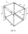
- FIGURE 2 is a perspective view of the prior art mounting rack described and claimed in U.S. Patent 4,998,636;
- FIGURE 3 is a perspective view of the assembled rack and mounting frame of the present invention;
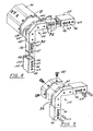
- FIGURE 4 is an exploded perspective view of the connection between the various frame members of the rack and mounting frame of the present invention;
- FIGURE 5 is a perspective view of the connection of a side frame member to the shoulder portion of the corner connector;
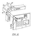
- FIGURE 6 is a perspective view showing the attachment of an electronic equipment module to the first panel of an assembled rack and mounting frame of the present invention; and
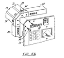
- FIGURE 6A is an alternate method for attachment of the equipment which the invention accommodates.
- FIGURE 7 is a perspective view of the rack and mounting frame of the present invention that has been further strengthened with brace members.
-
- FIGURE 1 is a representation of a prior art shipping and
storage container 10 which contains a rack and mountingframe 12 for mounting electronic equipment thereon. Theelectronic equipment 14 is provided with abezeled front panel 16 in which holes 18 are disposed for securing theequipment 14 to theframe 12. - As shown in FIGURE 2 and fully-described in U.S. Patent 4,998,636, the rack and
mounting frame 12 is constructed from a plurality of vertical andhorizontal members side frame members 24, all of which are preferably made from extruded, high tensile strength aluminum. The ends of each vertical 20, horizontal 22 andside frame members 24 are affixed to one another at right angles via an L-shapedinternal splice member 26 and an external splice (not shown) attached to one side of saidinternal splice member 26. - As further shown in FIGURE 2, the
side frame members 24 are provided with a pair ofrubber shock mounts 28 which are disposed at a 45° angle to the vertical members, in spaced relation, on eachside frame member 24, running in the fore-to-aft direction. Theshock mounts 28 are dimensional so that they engage brackets (not shown) mounted inside thecontainer 10, thereby suspending theframe 12 within the hollow interior thereof. - While the rack and
mounting frame 12 described above was an improvement over prior art frames which were welded together, saidframe 12 has limitations of manufacturing in that it requires different vertical andhorizontal frame members internal splice member 26. - The
rack system 30, according to the present invention, is shown in FIGURE 3 and is designed to overcome the deficiencies in the prior art rack system described above.Rack system 30, like the prior art device of FIGURE 2, employs a rectangular, parallelpiped frame structure comprising vertical andhorizontal frame members side frame members 36. Theside frame members 36 are provided with a pair of shock mounts 38, similar to those disclosed in connection with the prior art device shown in FIGURE 2, for mounting therack frame 30 within the hollow interior of a transport container. - The vertical and
horizontal frame members back frame panels rack system 30 are, preferably, extruded tubing most preferably having a rectangular cross-section with hollow interior 44 as illustrated in FIGURE 4. The tube may be hollow throughout or merely may have a receptacle end portion and otherwise be solid or otherwise obstructed. While both the horizontal andvertical frame members vertical frame members 32 are provided with a standard pattern of threaded mounting holes 46. This standard pattern is dictated under EIA-310-D for vertical members whereas it is not necessary for the horizontal members to include these holes. Theholes 46 extend the length of the front andrear walls frame members 32 for securing the front bezel panel of an electronic equipment module to the frame. In general, only the vertical frame members are employed to secure equipment. It is possible, however, to employ the horizontal members alone or in combination with the vertical members. As one of skill in the art will appreciate, however, horizontal members with no threaded holes and only pin holes are preferable, due to the cost of adding the unnecessary drilling and threading. - It should be noted that the front and back walls of the vertical frame member are most preferably 0.64cm (0.25") thick to provide sufficient screw thread length whereas the side walls are 0.203cm (0.080") thick to minimize weight of the completed rack.
- As shown in FIGURES 4 and 5, the
vertical frame member 32 and thehorizontal frame member 34 are joined together at theirdistal ends 52 via L-shapedinternal splice members 54. Each L-shapedinternal splice member 54 comprises avertical leg portion 56 and a horizontal leg portion 58 which are disposed and integrally joined at right angles by acentral portion 60 such that the outer face surfaces 62 ofleg portions 56 and 58 form a 45° ° angle with the outer face surfaces 64 of thecentral portion 60. Theleg portions 56 and 58 have a rectangular cross-section corresponding approximately to the cross-section of thehollow interiors 44 of the vertical andhorizontal frame members central portion 60 has a somewhat larger cross-section so as to provideabutments leg portions 56 and 58 into the vertical andhorizontal members - As also shown, the
central portions 60 of the L-shapedinternal splice member 54 are provided with ashoulder portion 66 which extends outward from aside surface 68 of thecentral portion 60. Theshoulder 66 receives and supports one of the ends ofside frame members 36. Thecentral portion 60 provides afurther abutment 93 to limit the engagement of theside frame members 36 with theshoulder 66. - It should also be noted that the L-shaped
internal splice member 54 is identical for all eight comers so that only one uniquely shaped member must be fabricated for the invention. - To assemble the vertical and
horizontal frame members rear frame panels vertical leg portion 56 of aninternal splice member 54 is inserted into thehollow interior 44 of avertical member 32 and the horizontal leg portion 58 of saidsplice member 54 is inserted into the hollow interior of ahorizontal frame member 34. When engaged with thesplice member 54, the horizontal, vertical and side frame member extend substantive perpendical to one another. Eachleg portion 56 and 58 is secured to theappropriate frame members members leg portions 56 and 58. Spiral spring pins are preferred for their high shear strength, low insertion force, and ability to be inserted automatically. Other pins, such as roll or solid pins, could also be used. The spring pins used are headless and have a length of less than the thickness of amember 32 so that they may be wholly inserted into the pin holes 69 so as to not interfere withholes 46 and/or bezel plate 70 of anelectronic equipment module 72 mounted to vertical frame members 32 (FIGURE 6). Pins are superior to threaded fasteners in this type of construction because they do not require a clearance fit in one of the members that they engage. The benefit of this is that the pin has an interference fit with both members making shear movements impossible unless the force exerted is beyond the yield strength of the parts or the pins themselves. Where in the prior art, friction was the only defense against these movements. Thus, the ability of the frame of the invention to withstand forces urging it out of square are greatly increased. - The
internal splice members 54 are machined to fit closely in thevertical frame members 32 in the fore-to-aft direction, but need not fit closely in the lateral direction. Saidsplice members 54 are also machined to provide a close fit inside thehorizontal frame members 34 in the fore-to-aft direction, but not in the vertical direction. - After all of the vertical and
horizontal frame members internal splice members 54 to make up front andrear frame portions rack frame 30, theside members 36 are ready to be assembled. As best illustrated in FIGURES 4, 5 and 6, theside members 36 are made from metal strips having aflat center portion 74 andouter portions 76 which are bent at 45° angles with respect to thecenter portion 74. The distal ends 78 of eachside member 36 are attached at each corner of the front andrear frame portions shoulder portion 66. As noted in the FIGURES, theshoulder portion 66 ofinternal splice member 54 is configured to match the configuration of theside members 36. - The
shoulder portion 66 is provided with a plurality of threadedholes 80 which receivemachine screws 82 which are used to hold the side members in engagement with theshoulder portions 66 of theinternal splice member 54. As clearly illustrated in FIGURES 4, 5 and 6, the thickness of the side frame member corresponds to the depth of theshoulder surface 66 below the outer face surfaces 62 and 64. - After all
side frame members 36 have been secured to the front andrear panel portions electronic equipment modules 72 can be mounted to therack 30 as shown in FIGURE 6. Eachmodule 72 is provided with a front bezel panel 70 which is an integral part of themodule 72.Holes 84, which follow EIA standards, are provided in bezel panel 70 so that said holes 84 align with threadedholes 46 provided along thefront side wall 48 of thevertical frame member 32 and on the front of splice-member 54. Screws 86 passing throughholes 84 and threaded intoholes 46 secure theelectronic equipment module 72 to therack 30. Depending largely upon the weight of the equipment to be secured any number of the threadedholes 46 might be employed. - The construction of the
rigid rack frame 30 is sufficient to withstand most impacts and vibrations transmitted through the shock mounts while preventing damage to sensitive electronic equipment secured thereto. However, should it be desirable to further strengthen theframe 30, diagonally-extendingbrace members 88 can be attached in the pattern illustrated in FIGURE 7. - In addition to the substantial structural integrity benefits of the invention, the invention is also significantly less expensive to manufacture than prior art units.
- For example:
Prior Art Invention 5 unique extruded shapes 3 unique extruded shapes 11 fasteners 7 fasteners 9 screws 3 screws 2 pins 4 pins 16 machine set-ups 11 machine set- ups 16 set-ups 11 set- ups 24 steps 15 steps - The cost savings of this manufacture is an important advance in the art.
- Although the invention has been described in connection with what is presently considered to be the most practical and preferred embodiment, it is to be understood that the invention is not to be limited to the disclosed embodiment, but, on the contrary, is intended to cover various modifications and equivalent arrangements within the scope of the appended claims.
Claims (15)
- An electronics rack and mounting frame (30), comprising a plurality of horizontal frame members (34), each of the horizontal frame members (34) having two ends (52) and having a pinhole (69) therethrough on both ends (52) thereof, a plurality of vertical frame members (32), each of the vertical frame members (32) having two ends (52) and having a pinhole (69) therethrough on both ends (52) thereof, a plurality of internal splice members (54), each of the splice members (54) having leg portions (56, 58) engageable within one end of a horizontal frame member (34) and one end of a vertical frame member (32), the leg portions (56, 58) including pin holes (67) alignable with the pinholes (69) in each of the horizontal frame members (34) and the vertical frame members (32), a plurality of pins (63) pressed into the pinholes (67) when the pinholes (69) are aligned, the pins (63) fastening the horizontal frame member (34) and the vertical frame member (32) to the splice member (54), characterised in that each of the splice members (54) further includes an integrally formed central portion (60) providing a first planar abutment (92) for limiting the engagement of the splice member (54) with the horizontal frame member (34) and a second planar abutment (90) for limiting the engagement of the splice member (54) with the vertical frame member (32).
- An electronics rack and mounting frame as claimed in Claim 1 characterised in that the electronics rack and mounting frame (30) further comprises a plurality of side members (36), each of the side members (36) having two ends (78) and having a pinhole therethrough on both ends (78) thereof, and each of the splice members (54) being engageable with one side member (36).
- An electronics rack and mounting frame as claimed in Claim 2 characterised in that the central portion (60) provides a third planar abutment (93) for limiting engagement of the splice member (54) with the side member (36), and the third planar abutment (93) is substantially perpendicular to the first and second planar abutments (92 and 90).
- An electronics rack and mounting frame as claimed in Claim 2 or Claim 3 characterised in that the horizontal frame member (34), the vertical frame member (32) and the side member (36) extend substantially perpendicularly from one another when engaged with the splice member (54).
- An electronics rack and mounting frame as claimed in any one of Claims 2-4 characterised in that the central portion (60) includes an exterior surface which is substantially co-planar with an exterior surface of the horizontal frame member (34), an exterior surface of the vertical frame member (32) and an exterior surface of the side member (36) when the horizontal frame member (34) abuts the first planar abutment (92), the vertical frame member (32) abuts the second planar abutment (90) and the side member (36) abuts the third planar abutment (93).
- An electronics rack and mounting frame according to any one of the preceding claims characterised in that the horizontal frame members (34) and the vertical frame members (32) have axial receptacles (44) formed in the two ends (52).
- An electronics rack and mounting frame as claimed in Claim 6 characterised in that the leg portions (56, 58) of each splice member (54) extend from the central portion (60), the leg portions (56, 58) being oriented substantially perpendicularly from one another and dimensioned to be accepted into the axial receptacles (44) of the horizontal and the vertical frame members (34,32).
- An electronics rack and mounting frame according to any one of the preceding claims characterised in that the pins (63) connecting the horizontal and vertical frame members (34,32) to the splice members (54) are one of a spring pin, a roll pin and a solid pin.
- An electronics rack and mounting frame according to any one of the preceding claims characterised in that the central portion (60) defines a chamfered profile.
- An electronics rack and mounting frame as claimed in any one of Claims 2-5 characterised in that each splice member (54) further comprises a shoulder portion (66) extending outward from a side surface (68) of the central portion (60) for attachment to one of the side members (36), for example by a plurality of screws (82).
- An electronics rack and mounting frame as claimed in any one of the preceding claims characterised in that the pin holes (67) provide an interference fit for the pins (63).
- An electronics rack and mounting frame as claimed in any one of Claims 2-5 characterised in that the splice members (54) connect the horizontal and vertical frame members (34,32) to form front and rear panels (40,42) and the side frame members (36) connect the front and rear panels (40,42).
- An electronics rack and mounting frame as claimed in any one of the preceding claims characterised in that the splice members (54) are substantially identical to each other.
- An electronics rack and mounting frame according to any one of the preceding claims characterised in that the plurality of vertical frame members (32) and the plurality of horizontal frame members (34) are one of tube shaped, rectangular shaped and cylindrical shaped, and are preferably made hollow throughout their entire lengths, for example from an extrudable, high tensile strength aluminium material.
- An electronics rack and mounting frame according to any one of the preceding claims characterised in that the vertical frame members (32) include threaded holes (46) preferably arranged according to standard EIA-310-D for securing an electronic equipment module (72) to the electronics rack and mounting frame, and the horizontal frame members (34) optionally include threaded holes (46).
Applications Claiming Priority (2)
| Application Number | Priority Date | Filing Date | Title |
|---|---|---|---|
| US720206 | 1996-09-25 | ||
| US08/720,206 US5873480A (en) | 1996-09-25 | 1996-09-25 | Electronic rack and mounting frame |
Publications (3)
| Publication Number | Publication Date |
|---|---|
| EP0833552A2 EP0833552A2 (en) | 1998-04-01 |
| EP0833552A3 EP0833552A3 (en) | 1998-05-20 |
| EP0833552B1 true EP0833552B1 (en) | 2003-05-02 |
Family
ID=24893085
Family Applications (1)
| Application Number | Title | Priority Date | Filing Date |
|---|---|---|---|
| EP97307540A Expired - Lifetime EP0833552B1 (en) | 1996-09-25 | 1997-09-25 | Improved electronic rack and mounting frame |
Country Status (5)
| Country | Link |
|---|---|
| US (1) | US5873480A (en) |
| EP (1) | EP0833552B1 (en) |
| JP (1) | JPH10190260A (en) |
| CA (1) | CA2216392C (en) |
| DE (1) | DE69721425T2 (en) |
Families Citing this family (29)
| Publication number | Priority date | Publication date | Assignee | Title |
|---|---|---|---|---|
| US6180879B1 (en) * | 1996-06-20 | 2001-01-30 | Arlington Industries, Inc. | Electric box extender and supplemental parts |
| US6369322B1 (en) * | 1996-06-19 | 2002-04-09 | Arlington Industries, Inc. | Electric box extender and supplemental parts |
| US6802575B1 (en) | 2002-09-05 | 2004-10-12 | Harry P. Lee | Rack mount |
| US7267229B2 (en) * | 2004-11-12 | 2007-09-11 | Cheng Shun Chen | Foldable container device |
| USD559545S1 (en) | 2006-07-27 | 2008-01-15 | Boyt Harness Company, L.L.C. | Container |
| US7451872B1 (en) * | 2006-07-27 | 2008-11-18 | Boyt Harness Company, Llc | Weaponry container having a rigid outer surface |
| USD559544S1 (en) | 2006-07-27 | 2008-01-15 | Boyt Harness Company, L.L.C. | Container |
| TW201200073A (en) * | 2010-06-17 | 2012-01-01 | yong-yu Li | Assembly-type frame device |
| CN102316697A (en) * | 2010-07-09 | 2012-01-11 | 鸿富锦精密工业(深圳)有限公司 | Machine cabinet frame |
| CN102340942A (en) * | 2010-07-19 | 2012-02-01 | 鸿富锦精密工业(深圳)有限公司 | Server Cabinet |
| CN102340968A (en) * | 2010-07-28 | 2012-02-01 | 鸿富锦精密工业(深圳)有限公司 | Server cabinet framework and assembly method thereof |
| US8413833B1 (en) | 2010-09-03 | 2013-04-09 | TCF Composites, LLC | Ruggedized composite rack mount transport case |
| JP5559135B2 (en) * | 2011-12-22 | 2014-07-23 | タキゲン製造株式会社 | Equipment storage rack |
| JP5722859B2 (en) * | 2012-10-05 | 2015-05-27 | タキゲン製造株式会社 | Equipment storage rack |
| JP5722858B2 (en) * | 2012-10-05 | 2015-05-27 | タキゲン製造株式会社 | Equipment storage rack |
| JP6148200B2 (en) * | 2014-04-24 | 2017-06-14 | Necエンジニアリング株式会社 | Storage rack |
| GB2529827B (en) * | 2014-09-02 | 2017-01-04 | Cp Cases Ltd | Electronic rack and mounting chassis |
| JP6416596B2 (en) * | 2014-11-19 | 2018-10-31 | Necプラットフォームズ株式会社 | Storage rack |
| JP6258902B2 (en) * | 2015-09-10 | 2018-01-10 | Necプラットフォームズ株式会社 | Storage rack |
| US10648497B2 (en) * | 2016-06-24 | 2020-05-12 | Mac Goelst | Connectable box carcass framework members |
| JP6423477B2 (en) * | 2017-03-31 | 2018-11-14 | Necプラットフォームズ株式会社 | Storage rack |
| TWI635791B (en) * | 2017-05-26 | 2018-09-11 | 酷碼科技股份有限公司 | Support rod and casing containing support rod |
| USD904830S1 (en) | 2017-12-14 | 2020-12-15 | Dometic Sweden Ab | Soft bag cooler |
| AU201717676S (en) | 2017-12-14 | 2018-01-16 | Dometic Sweden Ab | Zip Puller |
| US20190254239A1 (en) * | 2018-02-21 | 2019-08-22 | Dwayne Williams | Planter box |
| US10653022B2 (en) * | 2018-09-10 | 2020-05-12 | Caci, Inc.-Federal | Deployable hardened housing units |
| US11313434B2 (en) | 2020-06-30 | 2022-04-26 | Rolls-Royce North American Technologies, Inc. | Shock absorption bracket |
| CN111918496B (en) * | 2020-07-14 | 2024-10-22 | 成都北翱科技有限公司 | Concatenation formula machine case |
| GB2640553A (en) * | 2024-04-24 | 2025-10-29 | Cp Cases Ltd | Electronic Rack and Mounting Chassis |
Family Cites Families (11)
| Publication number | Priority date | Publication date | Assignee | Title |
|---|---|---|---|---|
| US3784043A (en) * | 1968-11-29 | 1974-01-08 | M Presnick | Lightweight collapsible structures |
| US3955702A (en) * | 1974-05-08 | 1976-05-11 | Esquire, Inc. | Enclosed box-like housings |
| GB1531234A (en) * | 1974-10-30 | 1978-11-08 | Lb Ltd | Construction of enclosures or containers |
| IT7521410U1 (en) * | 1975-05-06 | 1976-11-06 | Caimi Exp Snc | METAL FRAME FOR FURNITURE |
| US4284202A (en) * | 1979-10-19 | 1981-08-18 | Hardigg Industries, Inc. | Reusable container |
| FR2546361A1 (en) * | 1983-05-20 | 1984-11-23 | Alsthom Cgee | CABINET FOR ELECTRICAL EQUIPMENT |
| US4998636A (en) * | 1989-06-30 | 1991-03-12 | Hardigg Industries, Inc. | Electronic rack and mounting frame |
| US5123541A (en) * | 1991-03-26 | 1992-06-23 | Penda Corporation | Modular shipping container and clip for assembling components thereof |
| JP2514620Y2 (en) * | 1991-04-26 | 1996-10-23 | 村田機械株式会社 | Tray transport conveyor |
| DE4221119C2 (en) * | 1992-06-26 | 1995-07-20 | Knuerr Mechanik Ag | Equipment case |
| US5524383A (en) * | 1995-03-20 | 1996-06-11 | Sanko; Paul J. | Disassembleable portable cold frame apparatus |
-
1996
- 1996-09-25 US US08/720,206 patent/US5873480A/en not_active Expired - Lifetime
-
1997
- 1997-09-22 JP JP9257165A patent/JPH10190260A/en active Pending
- 1997-09-24 CA CA002216392A patent/CA2216392C/en not_active Expired - Lifetime
- 1997-09-25 DE DE69721425T patent/DE69721425T2/en not_active Expired - Lifetime
- 1997-09-25 EP EP97307540A patent/EP0833552B1/en not_active Expired - Lifetime
Also Published As
| Publication number | Publication date |
|---|---|
| CA2216392C (en) | 2003-12-23 |
| CA2216392A1 (en) | 1998-03-25 |
| DE69721425D1 (en) | 2003-06-05 |
| JPH10190260A (en) | 1998-07-21 |
| DE69721425T2 (en) | 2004-01-15 |
| US5873480A (en) | 1999-02-23 |
| EP0833552A3 (en) | 1998-05-20 |
| EP0833552A2 (en) | 1998-04-01 |
Similar Documents
| Publication | Publication Date | Title |
|---|---|---|
| EP0833552B1 (en) | Improved electronic rack and mounting frame | |
| US4998636A (en) | Electronic rack and mounting frame | |
| US6364262B1 (en) | Display assembly | |
| EP0708032A2 (en) | Shock and vibration damping arrangement for shipping container | |
| US6047838A (en) | Modular support post | |
| EP0576642B1 (en) | Sub-panel guide system for electrical enclosures | |
| US9775260B1 (en) | Brackets for use with three rack mount systems | |
| US20200113331A1 (en) | Utility rack having end supports with folding cross-members | |
| US5975314A (en) | Shipping rack | |
| US20100200716A1 (en) | Modular rack for electronic systems | |
| US5122928A (en) | Monitor housing | |
| EP0571392B1 (en) | Shelf system for use in delivery vans | |
| EP3992475B1 (en) | Connecting device | |
| US6915915B2 (en) | Shelf unit | |
| US20200156548A1 (en) | Reconfigurable Storage Tray for Vehicle | |
| US6119881A (en) | Assembly for fastening horizontal support frames to upright supports of a rack | |
| US4006949A (en) | Cabinet for mounting electronic equipment | |
| US20240324775A1 (en) | Retaining bracket for modular shelving unit | |
| US20020179546A1 (en) | Apparatus for supporting articles | |
| JPH01179495A (en) | Structure of printed board housing unit | |
| WO1989000824A1 (en) | Shelf rack | |
| WO1996013184A1 (en) | Fastening device | |
| US5074701A (en) | Connector system for store fixtures | |
| JP2503781B2 (en) | Guide rail mounting structure for automatic warehouse loading / unloading equipment | |
| WO2026039861A1 (en) | "ladder storage rack" |
Legal Events
| Date | Code | Title | Description |
|---|---|---|---|
| PUAI | Public reference made under article 153(3) epc to a published international application that has entered the european phase |
Free format text: ORIGINAL CODE: 0009012 |
|
| AK | Designated contracting states |
Kind code of ref document: A2 Designated state(s): CH DE FR GB IT LI |
|
| AX | Request for extension of the european patent |
Free format text: AL;LT;LV;RO;SI |
|
| PUAL | Search report despatched |
Free format text: ORIGINAL CODE: 0009013 |
|
| AK | Designated contracting states |
Kind code of ref document: A3 Designated state(s): AT BE CH DE DK ES FI FR GB GR IE IT LI LU MC NL PT SE |
|
| AX | Request for extension of the european patent |
Free format text: AL;LT;LV;RO;SI |
|
| 17P | Request for examination filed |
Effective date: 19981111 |
|
| AKX | Designation fees paid |
Free format text: CH DE FR GB IT LI |
|
| RBV | Designated contracting states (corrected) |
Designated state(s): CH DE FR GB IT LI |
|
| 17Q | First examination report despatched |
Effective date: 20011115 |
|
| GRAG | Despatch of communication of intention to grant |
Free format text: ORIGINAL CODE: EPIDOS AGRA |
|
| GRAG | Despatch of communication of intention to grant |
Free format text: ORIGINAL CODE: EPIDOS AGRA |
|
| GRAG | Despatch of communication of intention to grant |
Free format text: ORIGINAL CODE: EPIDOS AGRA |
|
| GRAH | Despatch of communication of intention to grant a patent |
Free format text: ORIGINAL CODE: EPIDOS IGRA |
|
| GRAH | Despatch of communication of intention to grant a patent |
Free format text: ORIGINAL CODE: EPIDOS IGRA |
|
| GRAA | (expected) grant |
Free format text: ORIGINAL CODE: 0009210 |
|
| AK | Designated contracting states |
Designated state(s): CH DE FR GB IT LI |
|
| PG25 | Lapsed in a contracting state [announced via postgrant information from national office to epo] |
Ref country code: LI Free format text: LAPSE BECAUSE OF FAILURE TO SUBMIT A TRANSLATION OF THE DESCRIPTION OR TO PAY THE FEE WITHIN THE PRESCRIBED TIME-LIMIT Effective date: 20030502 Ref country code: IT Free format text: LAPSE BECAUSE OF FAILURE TO SUBMIT A TRANSLATION OF THE DESCRIPTION OR TO PAY THE FEE WITHIN THE PRESCRIBED TIME-LIMIT;WARNING: LAPSES OF ITALIAN PATENTS WITH EFFECTIVE DATE BEFORE 2007 MAY HAVE OCCURRED AT ANY TIME BEFORE 2007. THE CORRECT EFFECTIVE DATE MAY BE DIFFERENT FROM THE ONE RECORDED. Effective date: 20030502 Ref country code: CH Free format text: LAPSE BECAUSE OF FAILURE TO SUBMIT A TRANSLATION OF THE DESCRIPTION OR TO PAY THE FEE WITHIN THE PRESCRIBED TIME-LIMIT Effective date: 20030502 |
|
| REG | Reference to a national code |
Ref country code: GB Ref legal event code: FG4D |
|
| REG | Reference to a national code |
Ref country code: CH Ref legal event code: EP |
|
| REF | Corresponds to: |
Ref document number: 69721425 Country of ref document: DE Date of ref document: 20030605 Kind code of ref document: P |
|
| REG | Reference to a national code |
Ref country code: CH Ref legal event code: PL |
|
| ET | Fr: translation filed | ||
| PLBE | No opposition filed within time limit |
Free format text: ORIGINAL CODE: 0009261 |
|
| STAA | Information on the status of an ep patent application or granted ep patent |
Free format text: STATUS: NO OPPOSITION FILED WITHIN TIME LIMIT |
|
| 26N | No opposition filed |
Effective date: 20040203 |
|
| REG | Reference to a national code |
Ref country code: GB Ref legal event code: 732E Free format text: REGISTERED BETWEEN 20120426 AND 20120502 |
|
| REG | Reference to a national code |
Ref country code: DE Ref legal event code: R082 Ref document number: 69721425 Country of ref document: DE Representative=s name: PATENT- UND RECHTSANWAELTE HANSMANN & VOGESER, DE |
|
| REG | Reference to a national code |
Ref country code: DE Ref legal event code: R082 Ref document number: 69721425 Country of ref document: DE Representative=s name: WEICKMANN & WEICKMANN PATENT- UND RECHTSANWAEL, DE Effective date: 20120529 Ref country code: DE Ref legal event code: R082 Ref document number: 69721425 Country of ref document: DE Representative=s name: WEICKMANN & WEICKMANN PATENTANWAELTE - RECHTSA, DE Effective date: 20120529 Ref country code: DE Ref legal event code: R082 Ref document number: 69721425 Country of ref document: DE Representative=s name: PATENT- UND RECHTSANWAELTE HANSMANN & VOGESER, DE Effective date: 20120529 Ref country code: DE Ref legal event code: R081 Ref document number: 69721425 Country of ref document: DE Owner name: PELICAN PRODUCTS, INC. (N.D.GES.D. STAATES DEL, US Free format text: FORMER OWNER: HARDIGG INDUSTRIES, INC., SOUTH DEERFIELD, MASS., US Effective date: 20120529 |
|
| REG | Reference to a national code |
Ref country code: FR Ref legal event code: TP Owner name: PELICAN PRODUCTS, INC., US Effective date: 20120713 Ref country code: FR Ref legal event code: CL Name of requester: HARDIGG INDUSTRIES, INC., US Effective date: 20120713 |
|
| REG | Reference to a national code |
Ref country code: DE Ref legal event code: R082 Ref document number: 69721425 Country of ref document: DE Representative=s name: WEICKMANN & WEICKMANN PATENT- UND RECHTSANWAEL, DE Ref country code: DE Ref legal event code: R082 Ref document number: 69721425 Country of ref document: DE Representative=s name: WEICKMANN & WEICKMANN PATENTANWAELTE - RECHTSA, DE |
|
| REG | Reference to a national code |
Ref country code: FR Ref legal event code: PLFP Year of fee payment: 20 |
|
| PGFP | Annual fee paid to national office [announced via postgrant information from national office to epo] |
Ref country code: DE Payment date: 20160920 Year of fee payment: 20 Ref country code: GB Payment date: 20160921 Year of fee payment: 20 |
|
| PGFP | Annual fee paid to national office [announced via postgrant information from national office to epo] |
Ref country code: FR Payment date: 20160816 Year of fee payment: 20 |
|
| REG | Reference to a national code |
Ref country code: DE Ref legal event code: R071 Ref document number: 69721425 Country of ref document: DE |
|
| REG | Reference to a national code |
Ref country code: GB Ref legal event code: PE20 Expiry date: 20170924 |
|
| PG25 | Lapsed in a contracting state [announced via postgrant information from national office to epo] |
Ref country code: GB Free format text: LAPSE BECAUSE OF EXPIRATION OF PROTECTION Effective date: 20170924 |