EP0431039B1 - Anordnung zum bohren von löchern im boden - Google Patents
Anordnung zum bohren von löchern im boden Download PDFInfo
- Publication number
- EP0431039B1 EP0431039B1 EP89909877A EP89909877A EP0431039B1 EP 0431039 B1 EP0431039 B1 EP 0431039B1 EP 89909877 A EP89909877 A EP 89909877A EP 89909877 A EP89909877 A EP 89909877A EP 0431039 B1 EP0431039 B1 EP 0431039B1
- Authority
- EP
- European Patent Office
- Prior art keywords
- head
- conduit
- hole
- longitudinal axis
- forming
- Prior art date
- Legal status (The legal status is an assumption and is not a legal conclusion. Google has not performed a legal analysis and makes no representation as to the accuracy of the status listed.)
- Expired - Lifetime
Links
- 239000012530 fluid Substances 0.000 claims abstract description 15
- 239000000463 material Substances 0.000 claims description 3
- 239000002689 soil Substances 0.000 description 3
- 230000003247 decreasing effect Effects 0.000 description 2
- 239000004927 clay Substances 0.000 description 1
- 238000010276 construction Methods 0.000 description 1
- 230000000694 effects Effects 0.000 description 1
- 239000002245 particle Substances 0.000 description 1
- 230000000149 penetrating effect Effects 0.000 description 1
- 230000002093 peripheral effect Effects 0.000 description 1
Images

Classifications
-
- E—FIXED CONSTRUCTIONS
- E21—EARTH OR ROCK DRILLING; MINING
- E21B—EARTH OR ROCK DRILLING; OBTAINING OIL, GAS, WATER, SOLUBLE OR MELTABLE MATERIALS OR A SLURRY OF MINERALS FROM WELLS
- E21B7/00—Special methods or apparatus for drilling
- E21B7/04—Directional drilling
- E21B7/06—Deflecting the direction of boreholes
- E21B7/064—Deflecting the direction of boreholes specially adapted drill bits therefor
-
- E—FIXED CONSTRUCTIONS
- E21—EARTH OR ROCK DRILLING; MINING
- E21B—EARTH OR ROCK DRILLING; OBTAINING OIL, GAS, WATER, SOLUBLE OR MELTABLE MATERIALS OR A SLURRY OF MINERALS FROM WELLS
- E21B7/00—Special methods or apparatus for drilling
- E21B7/04—Directional drilling
- E21B7/06—Deflecting the direction of boreholes
- E21B7/065—Deflecting the direction of boreholes using oriented fluid jets
Definitions
- the present invention relates to a device for boring holes in the ground.
- the device includes a hollow, flexible conduit, a head which is connected to one end of the conduit and which is fitted with at least one nozzle through which fluid passing along the conduit under pressure is delivered in such a direction and under such pressure that when the head is not in rotation, the head will form a hole of curved configuration and such that when the head rotates about its longitudinal axis and the conduit is moved forwards in the hole-forming direction the head will form a substantially straight hole, the end of said head facing towards the hole-forming direction being provided with a surface which is positioned obliquely to the longitudinal axis of the head and which assists the head in forming said hole.
- An object of the present invention is to improve devices of the aforesaid kind, and to provide such a device which will enable the head to be steered in a desired path, substantially irrespective of the nature of the ground in which the holes are formed, and which is reliable in operation and of simple construction.
- All of the hole-forming devices illustrated in the drawings are intended for connection to conventional equipment for advancing the device and forming holes or bores in the ground.
- This equipment includes a hollow conduit, of which a part is shown in Figure and referenced 1.
- One end of the conduit 1 is connected to the device whereas the other end of the conduit is connected to a machine which functions to urge the conduit in a direction towards the bottom of the hole being formed and to rotate the head when forming a straight hole.
- the machine also functions to deliver pressure fluid to the device and to detect the position of the device in the ground and to send signals to machine operator responsible for causing the machine to carry out these and other machine functions.
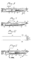
- the device illustrated in figures 1 and 2 includes a substantially round cylindrical head 2 which is connected at its rear end to the conduit 1 and the front end of which, as seen in the forward drive direction of the device, is provided with a surface which is positioned obliquely to the longitudinal center axis of the head, and therewith to the longitudinal center axis of the conduit 1, and which is formed on a substantially flat plate 3.
- the plate 3 has a forwardly located surface which is larger than the surface on the head 2 to which the plate 3 is attached and which is much larger than the cross-sectional area of the head.
- the angle of the plate 3 in relation to the longitudinal axis of the head 2 is between 10 and 40°, preferably about 20°. This angle cannot be changed in the case of the embodiment shown in Figures 1 and 2, since the plate 3 of this embodiment is welded to the head.
- the head 2 is configured with one or more passages 4, which communicate with the conduit 1 and open at the forward end of the head, at a short distance from the plate 3, where a nozzle 5 of small through-flow area is mounted in each passage.
- the nozzles are directed so that the stream of fluid exiting therefrom will form essentially the same angle with the longitudinal axis of the head as the oblique surface.
- the plate 3 of relative larger size than the head 2 in the embodiment illustrated in Figures 1 and 2 is operative to ensure that the head, when not in rotation, will be steered in the desired curved path, instead of in a straight path or a path of only small deviation, as would be the case if the plate were not provided.
- Figures 3 and 4 illustrate a device which differs from that illustrated in Figures 1 and 2, insomuch as the plate 3 of the earlier embodiment has been replaced with an insert.
- Those components of the Figure 3 and 4 embodiment which correspond to the components of the embodiment illustrated in Figures 1 and 2 have been identified with the same reference numerals as those used in the earlier Figures, but with the inclusion of a prime.
- This insert, referenced 6, is inserted into a recess in the head 2 and is detachably secured in the recess by means of screws 7.
- Guide pins 8, which are passed through concentric holes in the head 2' and into the insert 6, prevent the screws from being subjected to heavy strain during operation.
- the insert 6 has a forwardly located oblique surface which corresponds in the main to the front surface of the plate 3 in Figure 1 with respect to the angle of inclination of said surface and its size in relation to the head.
- the insert 6 can be replaced with a similar insert of another configuration and having an oblique surface which is inclined at a different angle than the former surface.
- the device illustrated in Figures 3 and 4 can, among other things, be adapted quickly to mutually different types of ground soil and the insert can be made of a tougher material than the head in general.
- FIGS 5 and 6 in which components corresponding to the embodiments above described have been identified with like reference numerals to which a double-prime has been added, illustrate an embodiment of the inventive device which differs from the embodiment illustrated in Figures 1 and 2, in that the oblique surface is formed directly on the head 2" (at 9) and has a stepped configuration, said surface optionally being configured with a plurality of steps 9a - 9d, or only one of these steps, as in the case of the embodiment shown in Figure 5.
- the steps will preferably form a right angle to the longitudinal axis of the head.
- the device illustrated in Figures 5 and 6 provides a better steering or guiding effect - when the device is not in rotation - than conventional devices of this kind, since the active guide surface area is increased without said surface extending beyond the peripheral confines of the hole-forming head.
- Figure 7 illustrates an embodiment of the inventive device which differs from that illustrated in Figure 3 insomuch as the insert 6' in Figure 7 may be titled relative to the head 2', such as to change the angle formed by the front surface of the insert with the longitudinal axis of the head.
- This can be achieved, for instance, by providing hinge means and angle adjusting devices between the head and the insert, but in Figure 7 such angle adjustments is made by inserting distance bodies, such as a washer 10, of varying thicknesses between the insert and the head 2'.
- Figures 8 - 11 illustrate embodiments of the inventive device where members corresponding to the plate 3 or insert 6 are hinged to the head and adjusting means are provided between the members and the head for adjusting the members to desired angles relatively to the longitudinal axis of the head.
- FIG 8 there is shown a head 11 with a plate-like member 12 being hinged to the front of the head.
- the head 11 is provided with two paral- lell passages 13 which communicate with a conduit, such as the one shown in Figure 1 , and open at the forward end of the head where one nozzle 14 for each passage is mounted.
- Member 12 has an ear 12a rotatably mounted to the head 11 at a location between the two nozzles 14.
- a radio signal receiver 15 including batteries and an electric motor 16 connected to the receiver 15 by cables 17.
- the shaft 18 of the motor 16 is provided with threads cooperating with internal threads in a sleeve 19 which is movable axially in the head but not permitted to rotate.
- the forward end of the sleeve 19 is adapted to contact member 12.
- the receiver 15 sends signals to the motor 16 to rotate the shaft 18 in order to move the sleeve 19 and thus swing the member 12 to an appropriate angle.
- the actuation of the member 12 may be performed during the operation of the device.
- FIGS 9 - 11 there is shown a head 20 with a U-shaped member 21 including an obliquely positioned plate 21 a and two side flanges 21 b.
- Member 21 has an ear 21 rotatably mounted to the head 20 at a location between two nozzles 22 communicating with two passages 28.
- the inner surfaces of the flanges 21 b cooperate with surfaces on the head 20 to minimize stresses on the member 21 and its mounting means during the rotation of the head 20.
- a plunger 23 is axially movable.
- a detachable locking ring 24 prevents the plunger from moving to the left in Figures 9 and 11.
- a spring 25 urges the plunge against the ring 24.
- a pawl 26 is swingably mounted in the head and cooperates with the plunger 23 as will be described below.
- the nozzle 27 communicates with the passages 28.
- the nozzle 27 has a fluid flow passage less than that of the nozzles 22 and prevents earth, soil, etc. from gathering between the head 20 and the member 21. The fluid flow from the nozzle 27 will be reflected by the plate 21 a and directed backwards along the head 20.
Landscapes
- Geology (AREA)
- Life Sciences & Earth Sciences (AREA)
- Engineering & Computer Science (AREA)
- Mining & Mineral Resources (AREA)
- Environmental & Geological Engineering (AREA)
- Fluid Mechanics (AREA)
- Physics & Mathematics (AREA)
- General Life Sciences & Earth Sciences (AREA)
- Geochemistry & Mineralogy (AREA)
- Earth Drilling (AREA)
- Consolidation Of Soil By Introduction Of Solidifying Substances Into Soil (AREA)
- Excavating Of Shafts Or Tunnels (AREA)
- Soil Working Implements (AREA)
Claims (10)
Applications Claiming Priority (2)
| Application Number | Priority Date | Filing Date | Title |
|---|---|---|---|
| SE8803046A SE464145B (sv) | 1988-08-31 | 1988-08-31 | Anordning foer upptagning av haal i marken |
| SE8803046 | 1988-08-31 |
Publications (2)
| Publication Number | Publication Date |
|---|---|
| EP0431039A1 EP0431039A1 (de) | 1991-06-12 |
| EP0431039B1 true EP0431039B1 (de) | 1994-03-02 |
Family
ID=20373172
Family Applications (1)
| Application Number | Title | Priority Date | Filing Date |
|---|---|---|---|
| EP89909877A Expired - Lifetime EP0431039B1 (de) | 1988-08-31 | 1989-08-29 | Anordnung zum bohren von löchern im boden |
Country Status (8)
| Country | Link |
|---|---|
| US (1) | US5020608A (de) |
| EP (1) | EP0431039B1 (de) |
| AU (1) | AU4185089A (de) |
| CA (1) | CA1318313C (de) |
| DE (1) | DE68913546T2 (de) |
| DK (1) | DK167582B1 (de) |
| SE (2) | SE464145B (de) |
| WO (1) | WO1990002242A1 (de) |
Families Citing this family (27)
| Publication number | Priority date | Publication date | Assignee | Title |
|---|---|---|---|---|
| USRE37975E1 (en) | 1988-06-27 | 2003-02-04 | The Charles Machine Works, Inc. | Directional boring head with blade assembly |
| US5341887A (en) * | 1992-03-25 | 1994-08-30 | The Charles Machine Works, Inc. | Directional multi-blade boring head |
| US5799740A (en) * | 1988-06-27 | 1998-09-01 | The Charles Machine Works, Inc. | Directional boring head with blade assembly |
| USRE37450E1 (en) * | 1988-06-27 | 2001-11-20 | The Charles Machine Works, Inc. | Directional multi-blade boring head |
| US5242026A (en) * | 1991-10-21 | 1993-09-07 | The Charles Machine Works, Inc. | Method of and apparatus for drilling a horizontal controlled borehole in the earth |
| US5148880A (en) * | 1990-08-31 | 1992-09-22 | The Charles Machine Works, Inc. | Apparatus for drilling a horizontal controlled borehole in the earth |
| US5941322A (en) * | 1991-10-21 | 1999-08-24 | The Charles Machine Works, Inc. | Directional boring head with blade assembly |
| DE4305423C2 (de) * | 1993-02-22 | 1996-11-07 | Terra Ag Tiefbautechnik | Erdbohrgerät |
| DE4433533C1 (de) * | 1994-09-20 | 1995-11-23 | Terra Ag Tiefbautechnik | Rammbohrvorrichtung |
| ATE199273T1 (de) * | 1996-03-04 | 2001-03-15 | Vermeer Mfg Co | Verfahren und vorrichtung zum richtungsbohren |
| AUPO062296A0 (en) * | 1996-06-25 | 1996-07-18 | Gray, Ian | A system for directional control of drilling |
| US6209660B1 (en) * | 1997-02-05 | 2001-04-03 | New Railhead Manufacturing, L.L.C. | Drill bit shear relief for horizontal directional drilling of rock formations |
| US6125950A (en) * | 1998-12-15 | 2000-10-03 | Osborne; Joseph D. | Collared boring bit |
| US6161636A (en) * | 1998-12-15 | 2000-12-19 | Osborne; Joseph D. | Boring head and bit protective collar |
| US6357537B1 (en) | 2000-03-15 | 2002-03-19 | Vermeer Manufacturing Company | Directional drilling machine and method of directional drilling |
| US6491115B2 (en) | 2000-03-15 | 2002-12-10 | Vermeer Manufacturing Company | Directional drilling machine and method of directional drilling |
| US6810972B2 (en) * | 2002-02-08 | 2004-11-02 | Hard Rock Drilling & Fabrication, L.L.C. | Steerable horizontal subterranean drill bit having a one bolt attachment system |
| US6827159B2 (en) * | 2002-02-08 | 2004-12-07 | Hard Rock Drilling & Fabrication, L.L.C. | Steerable horizontal subterranean drill bit having an offset drilling fluid seal |
| US6814168B2 (en) * | 2002-02-08 | 2004-11-09 | Hard Rock Drilling & Fabrication, L.L.C. | Steerable horizontal subterranean drill bit having elevated wear protector receptacles |
| US6810971B1 (en) * | 2002-02-08 | 2004-11-02 | Hard Rock Drilling & Fabrication, L.L.C. | Steerable horizontal subterranean drill bit |
| US6810973B2 (en) * | 2002-02-08 | 2004-11-02 | Hard Rock Drilling & Fabrication, L.L.C. | Steerable horizontal subterranean drill bit having offset cutting tooth paths |
| US7628212B2 (en) * | 2006-10-26 | 2009-12-08 | Tt Technologies, Inc. | Drill stem connection and method |
| US8939237B2 (en) | 2010-11-12 | 2015-01-27 | Vermeer Manufacturing Company | Underground drilling apparatus |
| WO2015031082A1 (en) | 2013-08-29 | 2015-03-05 | Vermeer Manufacturing Company | Drilling tool and apparatus |
| US11629556B2 (en) * | 2018-02-23 | 2023-04-18 | Melfred Borzall, Inc. | Directional drill bit attachment tools and method |
| WO2022020321A1 (en) * | 2020-07-21 | 2022-01-27 | Kondex Corporation | Enhanced drill bit profile for use in hdd |
| BR112023017504A2 (pt) * | 2021-04-06 | 2023-11-07 | Halliburton Energy Services Inc | Conjunto de bocais para sistemas de tubo de derivação |
Family Cites Families (17)
| Publication number | Priority date | Publication date | Assignee | Title |
|---|---|---|---|---|
| US3324957A (en) * | 1963-09-24 | 1967-06-13 | Gulf Research Development Co | Hydraulic jet method of drilling a well through hard formations |
| US3365007A (en) * | 1965-10-24 | 1968-01-23 | Wilson Supply Co | Directional drilling tool and method |
| US3525405A (en) * | 1968-06-17 | 1970-08-25 | Bell Telephone Labor Inc | Guided burrowing device |
| US3529682A (en) * | 1968-10-03 | 1970-09-22 | Bell Telephone Labor Inc | Location detection and guidance systems for burrowing device |
| US3746108A (en) * | 1971-02-25 | 1973-07-17 | G Hall | Focus nozzle directional bit |
| US4119160A (en) * | 1977-01-31 | 1978-10-10 | The Curators Of The University Of Missouri | Method and apparatus for water jet drilling of rock |
| US4306627A (en) * | 1977-09-22 | 1981-12-22 | Flow Industries, Inc. | Fluid jet drilling nozzle and method |
| US4401170A (en) * | 1979-09-24 | 1983-08-30 | Reading & Bates Construction Co. | Apparatus for drilling underground arcuate paths and installing production casings, conduits, or flow pipes therein |
| DE3029963C2 (de) * | 1980-08-07 | 1985-10-17 | Flow Industries, Inc., Kent, Wash. | Bohrdüse |
| US4725837A (en) * | 1981-01-30 | 1988-02-16 | Tele-Drill, Inc. | Toroidal coupled telemetry apparatus |
| US4416339A (en) * | 1982-01-21 | 1983-11-22 | Baker Royce E | Bit guidance device and method |
| GB2126267A (en) * | 1982-09-07 | 1984-03-21 | Coal Ind | Drilling methods and equipment |
| SE454196C (sv) * | 1983-09-23 | 1991-11-04 | Jan Persson | Jord- och bergborrningsanordning foer samtidig borrning och infodring av borrhaalet |
| US4674579A (en) * | 1985-03-07 | 1987-06-23 | Flowmole Corporation | Method and apparatus for installment of underground utilities |
| US4621698A (en) * | 1985-04-16 | 1986-11-11 | Gas Research Institute | Percussion boring tool |
| US4679637A (en) * | 1985-05-14 | 1987-07-14 | Cherrington Martin D | Apparatus and method for forming an enlarged underground arcuate bore and installing a conduit therein |
| DE3680402D1 (de) * | 1985-05-14 | 1991-08-29 | Cherrington Corp | Vorrichtung und verfahren zum herstellen eines vergroesserten gekruemmten bohrlochs im untergrund und zum installieren eines rohres darin. |
-
1988
- 1988-08-31 SE SE8803046A patent/SE464145B/sv not_active IP Right Cessation
-
1989
- 1989-08-29 DE DE68913546T patent/DE68913546T2/de not_active Expired - Fee Related
- 1989-08-29 WO PCT/SE1989/000452 patent/WO1990002242A1/en not_active Ceased
- 1989-08-29 AU AU41850/89A patent/AU4185089A/en not_active Abandoned
- 1989-08-29 EP EP89909877A patent/EP0431039B1/de not_active Expired - Lifetime
- 1989-08-29 US US07/435,461 patent/US5020608A/en not_active Expired - Fee Related
- 1989-08-30 CA CA000609769A patent/CA1318313C/en not_active Expired - Fee Related
- 1989-09-05 SE SE8902921A patent/SE464146B/sv not_active IP Right Cessation
-
1991
- 1991-02-14 DK DK025891A patent/DK167582B1/da active
Also Published As
| Publication number | Publication date |
|---|---|
| WO1990002242A1 (en) | 1990-03-08 |
| DE68913546T2 (de) | 1994-10-06 |
| DK167582B1 (da) | 1993-11-22 |
| DE68913546D1 (de) | 1994-04-07 |
| SE464146B (sv) | 1991-03-11 |
| EP0431039A1 (de) | 1991-06-12 |
| AU4185089A (en) | 1990-03-23 |
| SE8803046L (sv) | 1990-03-01 |
| SE8902921D0 (sv) | 1989-09-05 |
| SE8902921L (sv) | 1990-03-01 |
| US5020608A (en) | 1991-06-04 |
| DK25891A (da) | 1991-02-27 |
| CA1318313C (en) | 1993-05-25 |
| SE8803046D0 (sv) | 1988-08-31 |
| DK25891D0 (da) | 1991-02-14 |
| SE464145B (sv) | 1991-03-11 |
Similar Documents
| Publication | Publication Date | Title |
|---|---|---|
| US5020608A (en) | Device for boring holes in the ground | |
| US4974688A (en) | Steerable earth boring device | |
| DE60206276T2 (de) | Lenkbare drehbohrmeisseleinrichtung mit pilotbohrer | |
| BE1003502A6 (nl) | Stuurbare boormol. | |
| US5597283A (en) | Quick coupling for heavy equipment attachment | |
| EP0431293B1 (de) | Schildvortriebsmaschine | |
| US5687807A (en) | Cutter head for trenchless boring machine | |
| JP3361787B2 (ja) | ボーリング用の工具アセンブリ | |
| WO2001011193A1 (en) | Arrangement for fixing rock bolts during rock reinforcement | |
| WO2000024537A1 (en) | Portable single-point beveling tool | |
| GB2072238A (en) | Shearer drums of winning machines | |
| EP0324778A4 (de) | Bohrvorrichtung. | |
| EP0070325B1 (de) | Fluidimpulsgetriebenes Werkzeug mit Drehmomentbegrenzung | |
| US5111891A (en) | Boring head for a subsurface soil-boring apparatus | |
| CA2929838C (en) | Soil spreading scraper device including deflecting paddles | |
| EP0499820A1 (de) | Kugelausbohrwerkzeug | |
| WO1999023314B1 (en) | Steerable underwater plow | |
| US3850450A (en) | Top link apparatus | |
| US4974687A (en) | Soil displacement hammer | |
| GB1575371A (en) | Mining/tunnelling equipment | |
| DE3116984A1 (de) | Randstreifenmaehereinheit | |
| US6257221B1 (en) | Cutting machine | |
| DE3617790A1 (de) | Ultraschallbearbeitungsmaschine | |
| AU747836B2 (en) | Advancing device for boring sections of roadway, tunnels or similar | |
| GB2357105A (en) | Line marking head assembly and line marking apparatus including the same |
Legal Events
| Date | Code | Title | Description |
|---|---|---|---|
| PUAI | Public reference made under article 153(3) epc to a published international application that has entered the european phase |
Free format text: ORIGINAL CODE: 0009012 |
|
| AK | Designated contracting states |
Kind code of ref document: A1 Designated state(s): BE DE FR GB IT NL |
|
| 17P | Request for examination filed |
Effective date: 19910215 |
|
| 17Q | First examination report despatched |
Effective date: 19921201 |
|
| GRAA | (expected) grant |
Free format text: ORIGINAL CODE: 0009210 |
|
| AK | Designated contracting states |
Kind code of ref document: B1 Designated state(s): BE DE FR GB IT NL |
|
| PG25 | Lapsed in a contracting state [announced via postgrant information from national office to epo] |
Ref country code: IT Free format text: LAPSE BECAUSE OF FAILURE TO SUBMIT A TRANSLATION OF THE DESCRIPTION OR TO PAY THE FEE WITHIN THE PRE;WARNING: LAPSES OF ITALIAN PATENTS WITH EFFECTIVE DATE BEFORE 2007 MAY HAVE OCCURRED AT ANY TIME BEFORE 2007. THE CORRECT EFFECTIVE DATE MAY BE DIFFERENT FROM THE ONE RECORDED.SCRIBED TIME-LIMIT Effective date: 19940302 |
|
| REF | Corresponds to: |
Ref document number: 68913546 Country of ref document: DE Date of ref document: 19940407 |
|
| ET | Fr: translation filed | ||
| PLBE | No opposition filed within time limit |
Free format text: ORIGINAL CODE: 0009261 |
|
| STAA | Information on the status of an ep patent application or granted ep patent |
Free format text: STATUS: NO OPPOSITION FILED WITHIN TIME LIMIT |
|
| 26N | No opposition filed | ||
| PGFP | Annual fee paid to national office [announced via postgrant information from national office to epo] |
Ref country code: FR Payment date: 19960809 Year of fee payment: 8 |
|
| PGFP | Annual fee paid to national office [announced via postgrant information from national office to epo] |
Ref country code: GB Payment date: 19960820 Year of fee payment: 8 |
|
| PGFP | Annual fee paid to national office [announced via postgrant information from national office to epo] |
Ref country code: NL Payment date: 19960828 Year of fee payment: 8 |
|
| PGFP | Annual fee paid to national office [announced via postgrant information from national office to epo] |
Ref country code: DE Payment date: 19960906 Year of fee payment: 8 |
|
| PGFP | Annual fee paid to national office [announced via postgrant information from national office to epo] |
Ref country code: BE Payment date: 19961009 Year of fee payment: 8 |
|
| PG25 | Lapsed in a contracting state [announced via postgrant information from national office to epo] |
Ref country code: GB Free format text: LAPSE BECAUSE OF NON-PAYMENT OF DUE FEES Effective date: 19970829 |
|
| PG25 | Lapsed in a contracting state [announced via postgrant information from national office to epo] |
Ref country code: BE Free format text: LAPSE BECAUSE OF NON-PAYMENT OF DUE FEES Effective date: 19970831 |
|
| BERE | Be: lapsed |
Owner name: DIAMANT BOART CRAELIUS A.B. Effective date: 19970831 |
|
| PG25 | Lapsed in a contracting state [announced via postgrant information from national office to epo] |
Ref country code: NL Free format text: LAPSE BECAUSE OF NON-PAYMENT OF DUE FEES Effective date: 19980301 |
|
| GBPC | Gb: european patent ceased through non-payment of renewal fee |
Effective date: 19970829 |
|
| PG25 | Lapsed in a contracting state [announced via postgrant information from national office to epo] |
Ref country code: FR Free format text: LAPSE BECAUSE OF NON-PAYMENT OF DUE FEES Effective date: 19980430 |
|
| PG25 | Lapsed in a contracting state [announced via postgrant information from national office to epo] |
Ref country code: DE Free format text: LAPSE BECAUSE OF NON-PAYMENT OF DUE FEES Effective date: 19980501 |
|
| NLV4 | Nl: lapsed or anulled due to non-payment of the annual fee |
Effective date: 19980301 |
|
| REG | Reference to a national code |
Ref country code: FR Ref legal event code: ST |