EP0430933B1 - A method and apparatus for mechanical drying of an organic fibre based material as straw materials, peat, wooden chips and the like - Google Patents
A method and apparatus for mechanical drying of an organic fibre based material as straw materials, peat, wooden chips and the like Download PDFInfo
- Publication number
- EP0430933B1 EP0430933B1 EP87904876A EP87904876A EP0430933B1 EP 0430933 B1 EP0430933 B1 EP 0430933B1 EP 87904876 A EP87904876 A EP 87904876A EP 87904876 A EP87904876 A EP 87904876A EP 0430933 B1 EP0430933 B1 EP 0430933B1
- Authority
- EP
- European Patent Office
- Prior art keywords
- frame
- drying
- elements
- rick
- drying frame
- Prior art date
- Legal status (The legal status is an assumption and is not a legal conclusion. Google has not performed a legal analysis and makes no representation as to the accuracy of the status listed.)
- Expired - Lifetime
Links
Images


Classifications
-
- F—MECHANICAL ENGINEERING; LIGHTING; HEATING; WEAPONS; BLASTING
- F26—DRYING
- F26B—DRYING SOLID MATERIALS OR OBJECTS BY REMOVING LIQUID THEREFROM
- F26B9/00—Machines or apparatus for drying solid materials or objects at rest or with only local agitation; Domestic airing cupboards
- F26B9/10—Machines or apparatus for drying solid materials or objects at rest or with only local agitation; Domestic airing cupboards in the open air; in pans or tables in rooms; Drying stacks of loose material on floors which may be covered, e.g. by a roof
- F26B9/103—Machines or apparatus for drying solid materials or objects at rest or with only local agitation; Domestic airing cupboards in the open air; in pans or tables in rooms; Drying stacks of loose material on floors which may be covered, e.g. by a roof using fixed or removable drying air channels placed in the stack, e.g. horizontally or vertically
-
- A—HUMAN NECESSITIES
- A01—AGRICULTURE; FORESTRY; ANIMAL HUSBANDRY; HUNTING; TRAPPING; FISHING
- A01F—PROCESSING OF HARVESTED PRODUCE; HAY OR STRAW PRESSES; DEVICES FOR STORING AGRICULTURAL OR HORTICULTURAL PRODUCE
- A01F25/00—Storing agricultural or horticultural produce; Hanging-up harvested fruit
- A01F25/04—Stacks, ricks or the like
- A01F25/08—Ventilating means
-
- A—HUMAN NECESSITIES
- A01—AGRICULTURE; FORESTRY; ANIMAL HUSBANDRY; HUNTING; TRAPPING; FISHING
- A01F—PROCESSING OF HARVESTED PRODUCE; HAY OR STRAW PRESSES; DEVICES FOR STORING AGRICULTURAL OR HORTICULTURAL PRODUCE
- A01F25/00—Storing agricultural or horticultural produce; Hanging-up harvested fruit
- A01F25/12—Racks for drying purposes
-
- C—CHEMISTRY; METALLURGY
- C10—PETROLEUM, GAS OR COKE INDUSTRIES; TECHNICAL GASES CONTAINING CARBON MONOXIDE; FUELS; LUBRICANTS; PEAT
- C10F—DRYING OR WORKING-UP OF PEAT
- C10F5/00—Drying or de-watering peat
-
- A—HUMAN NECESSITIES
- A01—AGRICULTURE; FORESTRY; ANIMAL HUSBANDRY; HUNTING; TRAPPING; FISHING
- A01F—PROCESSING OF HARVESTED PRODUCE; HAY OR STRAW PRESSES; DEVICES FOR STORING AGRICULTURAL OR HORTICULTURAL PRODUCE
- A01F25/00—Storing agricultural or horticultural produce; Hanging-up harvested fruit
- A01F25/14—Containers specially adapted for storing
- A01F2025/147—Containers specially adapted for storing the containers are specially adapted for storing or drying the products in vacuum
-
- Y—GENERAL TAGGING OF NEW TECHNOLOGICAL DEVELOPMENTS; GENERAL TAGGING OF CROSS-SECTIONAL TECHNOLOGIES SPANNING OVER SEVERAL SECTIONS OF THE IPC; TECHNICAL SUBJECTS COVERED BY FORMER USPC CROSS-REFERENCE ART COLLECTIONS [XRACs] AND DIGESTS
- Y02—TECHNOLOGIES OR APPLICATIONS FOR MITIGATION OR ADAPTATION AGAINST CLIMATE CHANGE
- Y02A—TECHNOLOGIES FOR ADAPTATION TO CLIMATE CHANGE
- Y02A40/00—Adaptation technologies in agriculture, forestry, livestock or agroalimentary production
- Y02A40/10—Adaptation technologies in agriculture, forestry, livestock or agroalimentary production in agriculture
- Y02A40/51—Adaptation technologies in agriculture, forestry, livestock or agroalimentary production in agriculture specially adapted for storing agricultural or horticultural products
Definitions
- the primary objective of the invention here presented is to achieve an improved method and equipment for the mechanical drying of loose materials, especially organic fibre-based loose materials, in order that it would be possible to eliminate the characteristic drawbacks and weaknesses observed in earlier drying methods and to ensure the even distribution of a forced drying air flow throughout the material rick without material loss arid the risk of the absorption of ground moisture into the material rick.
- the invention is founded on the ingenious perception, that the thickness of the material rick heaped on top of the drying frame and the alignment relative to the drying frame can be visually determined by external inspection, and using then as part of the drying frame, vertical, e.g., post-like or similar elements as marking aids and horizontal, e.g. bar- or slim pole-like elements for height estimation and preventing compaction, and the edging equipment fitted to the sides of the drying frame composes uniform rick strength with sufficient accuracy and at the same time, with the aid of the longitudinal, supporting edging equipment horizontal to the earth, contact of the rick material with the ground can be prevented. Thanks to the even strength of construction through the rick it can now be ensured that there is an even flow of drying air through all parts of the rick, especially the peripheral zones of the rick near to the ground.
- the drying frame according to the invention and the edge fittings at its periphery are of simple construction and thus favourable for manufacture nor are there fan equipments to be rapidly exchanged, nor indeed any moving parts whatsoever, that the drying method or equipment do not impose any noteworthy limitations on the quantity of material to be dried, that due to the evenly distributed and forced airflow to all the parts of the rick the drying process is rapid, and is accompanied by a really favourable influence on the protein content in fodder intended for drying, and that the method or equipment according to the invention does not at all require monitoring work, naturally discounting the unavoidable protection of the material rick with the cover in the event of rainy weather.
- the loading and unloading of a drier according to the invention can be carried out economically and efficiently.
- a modularly constructed application according to the invention and especially one to be applied to large scale production of chips or peat this is realized so that the vertical bars protruding vertically from the drier frame can be removed and the outer walling edge parts can be taken down and/or removed.
- the covering element By optionnally using the covering element the whole rick surface can be used as a collector of solar thermal energy. In a traditional storage drier an expensive special solution for the collection of solar thermal energy is needed.
- an equipment according to one favourable mode of application of the invention primarily meant to be used in outside air, i.e. in field conditions and for the mechanical drying of organic fibre-based loose material, such as stalked materials, peat and wood chips etc, is formed of the drying frame 1, which limits the the drying air flow hollow or drying channel 2 on the underside extending to the ground, which channel will in future here be referred to as the air duct, and which together with the drying frame 1 and its edge fittings 15 carries the material to be dried as an even layer heaped into a rick in such manner that the material to be dried and the ground 3 do not come into contact with each other.
- the equipment according to the invention for the mechanical drying and attainment of forced air flow from air dust 2 through the material layer to outside air or conversely, from outer air through the material layer to air duct 2 includes fan unit 4, which is located in the end of duct 2.
- the drying equipment according to the invention optionally includes a covering unit 5, to be used particularly in rainy weather and to be spread over the material layer to be dried to prevent its becoming wet.
- the drying frame 1 includes several vertical, most advantageously post-like, vertical elements 11, favourably located at intervals between 0.5 - 2 m from each other and set into the earth along the same line, the length of each vertical being favourably between 2.0-4.0 m and carrying at a distance from the ground, favourably 2.0-0.3 m, one, most favourably bar-like, horizontal element 12, the length of which is favourably between 2.0-0.5 m and to tile free end of which element 12 is attached through an angle slanting downward from the horizontal a flank-, most favourably a bar-like element 13, the free end of which is supported against the ground.
- a vertical element 11, a horizontal element 12 and two flank elements compose in this mode of application one of the individual support frameworks of the drying frame on top of which the material intended for drying is heaped.
- the base fittings leave openings between both the horizontal elements 12, and located on top of flank elements 13 the longitudinal, favourably bar-like elements 14, favourably of slats, which extend either individually or fitted end to end in the direction of the flank element lengths, the opening size being selected each time depending on the size of the particles of the material to be dried and the length of the drying element frame 1.
- the drying frame includes at least a ground contact prevention edge 15 accompanying the drying frame as an edge fitting that extends to the ground at least on the longitudional side, edge 15 being supported against the ground and on top of it is piled the material to be dried that comes closest to the ground surface.
- the edge part mentioned in the advantageos mode of application according to Fig 1 is formed of several favourably pole-like elements 151, which are fitted parallel to each other at a short distance, favourably 1.0 - 5.0 m and against the ground for their whole length when it can be ensured that no air leakage occurs underneath the rick, but that all the air intended for drying only flows through the material layer to be dried to outside air or into the air duct and the rick is isolated from ground moisture.
- the material can be laid evenly and particularly that its upper parts are fundamentally in an uncompacted layer on top of the drying frame, and also that the air flow and its drying efficiency remain as evenly distribued as possible through the rick material while the drying of the material progresses.
- the free ends of the pole-like vertical elements 11 fundamentally project higher than the bar-like horizontal elements 12 fastened onto them, when the free ends of the aforementioned vertical elements 11 function on the one hand in heaping up the material to be dried onto the drying frame and on the other hand as aids in evaluating the thickness layer of the rick of material to be dried and again as an aid in evaluating the longitudional centre line of the rick to be formed.
- Fig. 3 is illustrated a favourable mode of application of a drying frame according to the invention, tapering towards its rear end.
- a drying frame meant for the drying of hay and stalk-like material in general the height of the air duct reduces, i.e.
- the pressure loss caused by the air flowing through the risk to outside can be compensated for and the pressure prevailing in the air duct is set to optimal for the material quantity at each point of the rick, which makes possible the progress of the drying front in all parts of the risk at fundamentally constant speed.
- the equipment according to the invention includes a covering unit 5 for preventing the stalked material from becoming vet in rainy weather, which when not in use is kept rolled up and when taken into use is spread out over the risk.
- the covering unit in the favourable mode of application of Fig 1 is composed of two covering elements fitted on both the long sides of the drying frame 1, for example of light coverings 5, each of which are rolled up at the lover edge of drying frame 1, favourably close to the drying frame edge fittings 15, from which position they can be drawn out over the risk to be dried and fastened from the free long edge with suitable fastening devices, for example with the aid of straps, ropes or similar means, to the vertical elements 11, so that along the line passing through the vertical elements 11 is left a space between the longitudinal edges of the light coverings 5, the gap 18 extending along the full length of the risk, through which the damp air can escape to the outside air.
- the rotation mechanism 52, 53 of the shaft of the covering roll 51 is used as the removal and setting device of the cover 5, which is fitted to the lower edge of the rick flat, whereupon moving of the cover is carried out by dragging it along the risk material surface.
- the covering roll can naturally be located when not in use close to the vertical elements 11 and that the covering roll can be rolled upwards or downwards along the risk flat, then by setting the direction of rotation of the covering roll the selection of either baring the risk (cover rolling up) or covering the risk (cover spreading over) can be decided.
- the rotation mechanism in formed at the grooved end of covering roll shaft 51 by using e.g.
- the known sprung-loaded, ball-locking, detachably connected power device which includes the lever arm 52 and ratchet mechanism 53.
- the power device in question other power devices, e.g. electrical or hydraulic power devices can naturally be used, the power output shaft of which, with suitable connection and power transmission, e.g. universal joint shaft, is connected to the covering roll shaft for its rotation
- the ends of the drying frame 1 can also be furnished with end elements or slats similar to flank elements 13 and end edging parts similar to the ground moisture prevention edging parts 15.
- the drying frame is then enclosed on all of its sides and also the ends of the drying frame car, be used as a base for the material to be dried. Additionally for the covering of the rick ends, end covers similar to the light covers described above, the gathering and spreading of which can be carried out when necessary in the manner described above.
- FIGs 2a, 2b and 2c some favourable shapes of air duct 2 within the limitations of the drying frame are illustrated.
- the shape in Fig 2a is identical to that of the first favourable mode of application of the invention described in Fig 1 excluding the transverse strengthening or support element 19 in the base of the drying frame, the purpose of which is to stiffen the frame against the transverse direction of loading, and the additional support element 20 between the joining points of flank and horizontal elements 11, 13 and the aforementioned support element 19.
- a curving part favourably of arced shape
- the drying element is formed of vertical element 11 and immediately to it are fastened one end of the straight flank elements 13 and the stiffening or supporting element 19 in the base of frame, a triangular frame being generally stiff.
- drying frame support frames according to these modes of application can be furnished with an additional supporting element 20, such as in the mode of application in Fig 2b link the stiffening or supporting part 19 and the joint of the horizontal element 12' and the flank element 13, such as in Fig 2c link together the strengthening or supporting element 19 and the flank element 13.
- the air duct 2 can also be dimensioned to accurately correspond to the needs in its breadth direction but if the support frames are made with standard, for example industrial, sizes similar fundamentally according to Figs 2a, 2b, 2c or 8 and if the attainment of even air over the whole rick length so requires, the drying frame can be furnished with edge fitting part 26 according to Fig 4, a part widening the edge of the drying area, which to advantage can be affixed steplessly in both breadth or height direction to the flank element of the drying frame support construction, and is thus intended to be located between the drying frame 1 proper and the ground moisture prevention edge part 15.
- the widening edge part 26 is made up of elements 262 in the transverse direction relative to the longitudinal axis of frame 1, which elements can be of any material, most suitable wood or plastic, and in each of which edge parts are at least two pieces each connected to the flank element 13 where it reaches the ground, and the side element 263 running in the same direction relative to the longitudinal axis of the hurdle frame 1, each of which elements 263 are fastened at least from both ends to the transverse elements 262 where their free ends protrude from hurdle frame 1.
- the edge widening part 26 includes in this mode of application a net base 264, in place of which slatting may also be used, and the net opening (or slat spacing) of which is made suitable for each material to be dried, i.e., the net openings that may be used with hay are larger than, for example those for use with wood chips, so that the material cannot spill through the net (or slat) openings inside the edge widening part 26.
- the edge widening part 26 is fastened for an arrangement in the transverse direction to drying frame 1, whereupon the edge widening part 26 can be set suitably for the layer thickness of each rick material, so that the outermost peripheral surface of the rick material layer does not extend to the outermost longitudinal element 151 of the ground moisture prevention part 15 to be fitted beside the edge widening part.
- a really thick rick layer can then be reliably isolated from the ground, and adverse air gaps are not created between ground and rick surfaces.
- FIGs 5a and 5b two favourable fitments for fastening the edge widening part 26 in place are presented.
- the locking fitment according to Figure 5a is formed of a generlly U-shaped metallic piece 6, the waist part of which is dimensioned to correspond to the height of the transverse element 262 of the edge widening part, and inside which the transverse element 262 is intended to fit.
- the forked parts of the U-piece then project beyond the transverse elements and in these forked parts are slots opening in opposite directions to each other and these are dimensioned to fit over the flank elements 13.
- the slots support the flank elements in opposite directions and thus hold the transverse element as well as the whole of the edge widening part firmly in the desired place.
- the whole position of the edge widening part 26 relative to drying frame 1 is changed especially in the lateral direction, but also when needed in the vertical direction.
- the locking fitment 6' is made from a formed plate in which there is a depression made to correspond with the shape of the flank element 13 and the height of which is dimensioned to correspond to the respective height of the transverse element 262.
- the locking fitment 6' according to this mode of application is used so that it is set over the flank element 13 and fastened, e.g., with screws in the desired place, whereupon the locking fitment 6' presses the flank element against the transverse element 262 and keeps it securely in place in the desired position.
- the position of the screw fastening the whole position of the widening edge part 26 relative to the drying frame 1 is changed.
- a third edging part according to one favourable mode of application of the invention is presented, i.e. a wall edging part 27, to be positioned in the direction of the longitudinal axis of drying frame 1, as an outer part of the edging equipment.
- the third edging part 27 according to this mode of this application is formed of a slat frame, which is arranged for folding on its long edge along the side of the drying frame, when it has the first framework part 275 supported on the ground and the second framework 276 that is intended for support by the external surface of the rick.
- this secondary mode of application includes at least one device 277 for the adjustment and locking of the angle of inclination between the first and second frameworks 275 and 276 which is fastened, for example, by pin connection from its first end arm-like to the other framework part 276, and the other end of which is furnished with, for example, a drilled or perforated plate, so that the hole of the drilled or perforated plate is dimensioned to fit onto the pin-like protruding parts 278 set apart at intervals, whereupon by changing the position of the other end of the adjustment and locking element in relation to the edge part of the first framework the angle of inclination of this third mode of edge part can be adjusted.
- the third edging part acccording to this mode of application can, if so desired, be furnished with a net (or with slats), the net opening size of which is selected to suit the material to be dried so that the material cannot spill through the openings in the net (or slats) to the ground.
- the third edging part according to Fig 6 is then favourably an airy wall part, the purpose of which is, especially when there are large quantities of material to he dried, ease in making the rick and ensuring that the rick is correct in relation to the drying frame and the air duct beneath it, and thus making possible an even material layer throughout and the ideal even throughflow of air and also even drying.
- the height of the rick in relation to its width can be greater than any natural spilling angle characteristic to the material would allow.
- the shape of the air duct cross-section can be selected more freely.
- the drying equipment according to the invention is thus formed of drying frame 1 which supports on its upper side the base fittings 14 for the material rick to be dried and limits on its lower side the air duct 2, to which is connected at least one fan device 4 for the creation of a drying air flow through the rick material layer, edge fittings, which consist of at least ground moisture prevention part 15 and wall edging part 27, or alternatively an edge widening part 26, ground moisture prevention part 15 and wall edging part 27, which edging parts keep the lowermost parts of the rick separated from the ground and especially the wall edging part 27 ensures correct location of the rick material relative to air duct 2, and an optionally used covering element, with which wetting of the rick is prevented if it rains.
- the wall edging part 27 being jointed can if need be dropped and/or removed if for example the emptying technique of the dryer so requires.
- Fig 8 a favourable mode of industrially manufactured drying hurdle of modular construction is presented, in which the manufacturing materials are favourably of plastic and metal.
- the supporting framework 1' of the drying frame is formed of the first transverse element 19 against the ground, and in rectangular cross-sectional form, and of the second transverse element 13, of circular arc form and of round cross-section, which is together with another transverse element in the same vertical plane, as well as several intermediate elements 11' connecting the transverse elements and supporting the support framework, round in cross-section, the central of which, i.e.
- the central intermediate element 11' passes through the curved transverse element 13' for the continuation of which, most suitably with a sleeve-like connection, is the vertical additional element 20, which functions as a marking device for the layer thickness and alignment of the rick material layer on top of the drying frame and also as a fastening support for the covering device spread over the material rick and is when necessary, for example when the dryer emptying technique so demands, easily removed from its sleeve or corresponding fastening.
- the drying frame 1' is stiffened in the longitudinal direction by a slanting supporting piece 28, which is fitted to connect the vertical intermediate support 11' and the strong longitudinal support 22 of at the least two successive supporting frameworks.
- Such support frames 1' described above are suited for the formation of a drying frame with spaces between each other in the longitudinal axis direction and then supported at the relevant separation distance by longitudional spacer elements 21, which are joined together most suitably by such a connection as is presented in Fig 9 or by some other easily installed and dismantled connection.
- This connection of the longitudinal elements 21 and the transverse element 19 has been so made that at one end of the longtudinal elements to be joined together there is a pin-like protrusion 23 and in the other end there is a corresponding opening 24 suited to fit around it.
- the projecting end of the transverse element 19 is located in between the longitudinal elements to be joined together and for that reason the opening 25 is made in it through which the aforementioned protrusion 23 is fitted.
- the drying frame includes a net element 14' as the base for the heaped rick material, with which the longitudinal slatting 14 constructed on top of the flank element 13, as described in connection with Fig 1 at the beginning of this patent application, can be substituted.
- Such a net can be extended in one piece over the whole drying frame area or be made up of two net elements, one of which coveres one half of the drying frame and the other correspondingly the other half. Further it is important that the net opening size is selected to correspond to the particle size of the rick material to be dried so that no unnecessary spillage of the material into the air duct occurs.
- the mechanical drying of the organic fibre-based loose material such as stalked materials peat, chips and the like is performed as follows:
- the fan equipment 4 includes a power drive device, favourably an electric motor and its driven rotor, as well as the support frame surrounding the rotor and the inblowing and/or outblowing flow duct that is fitted as the continuation of the support frame, the duct being directly connected to air duct 2 limited by the lower side of drying frame 1, whence the only path to the outside air is through the fan equipment or through the rick' when the path of the forced airflow from the fan duct through air duct 2 to outside air or conversely from outside air through air duct 2 to the fan duct only passes through the rick material to be dried.
- a power drive device favourably an electric motor and its driven rotor, as well as the support frame surrounding the rotor and the inblowing and/or outblowing flow duct that is fitted as the continuation of the support frame, the duct being directly connected to air duct 2 limited by the lower side of drying frame 1, whence the only path to the outside air is through the fan equipment or through the rick' when the path of the forced airflow from the fan
- connection is made as air-tight as possible, whereupon it is advantageous that the air duct projects some distance inside the drying frame 1 and that the end of the drying frame on the fan equipment 4 side is furnished with slanting vertical elements on top of which the material to be dried is set.
- Naturally fully enclosed end elements for example of plastic sheet, can be used, in which there is an opening dimensioned to correspond to the fan duct dimensions.
- the mounting of the fan motor 41 and the electrical installations 43 are so fashioned that the attachment of the support frame 46 to the fan duct casing 42 is performed with bolts 44 or by quickly locking catches, and that the electrical switches 43, i.e. the star-delta safety switch, the switch to change the direction of rotation and the electrical power plug are mounted onto the aforementioned support frame 43, whereupon the fan equipment can be transferred as a complete unit with the aid of support frame 43 to another operational site. It is then possible to manufacture the fan motor/electrical switch combination industrially and thanks to the direction of rotation switch the the fan blowing direction can be changed in order to even out moisture differences and utilize the weather conditions to the optimun so as to speed up the drying.
Abstract
Description
- A method and apparatus for mechanical drying of an organic fibre based material as straw materials, peat, wooden chips and the like.
- The subject matter of the invention here presented is a method according to the introductory part of the
Patent Claim 1 and an equipment according to the introductory part ofPatent Claim 5 for the mechanical drying organic fibre-based loose materials, such as stalked materials, peat, wood chip and corresponding materials. - Endeavours have earlier been made in many different, ways to solve the drying of such materials, amongst which can be mentioned
- a drying frame according to the patent application publication DE 1143357, to which it is characteristic that the hurdle frame and the material loaded onto it are separated from the ground surface in order to create a free air flow inside the frame.
- the multi-layered repair and storage frame built onto a trailor and according to the patent application FI-3490/71 in which the material to be dried is laid out in several layers separated from one another in order to create a free air flow in between the material layers.
- a mobile ricking device according to patent publication FI-28291 for peat or similar material, which consists of two moving side walls in between which the peat is transferred from the conveyor, whereupon the peat falls between the side walls partly against the ground and partly onto the net, the purpose of which is to form a channel to the peat rick, the intention thereof being to improve airing of the peat rick and its drying.
- a method according to the patent publication FI-67260 for roofing and drying the rick, in which solution a perforated pipe is used inside the rick as the drying device. The pipe is connected to a fan and in this solution a roof is used to cover the rick, which is formed of two perforated sheets set in relation to each other.
- a method according to the patent publication FI-61357 for the drying of fresh grass or similar material, in which solution the material to be dried is ricked partly against the base and partly on the top of a latticed drying frame of truncated pyramid form, beneath which a fan has been arranged.
- a barn dryer according to the patent publication GB-1451957, to which it is characteristic that it includes a shelter from one end of which a tractor can be driven in and at the other end of which there is a fan for creating an air flow from one end of the aforementioned shelter to the space at the other end of the abovementioned shelter which is to be dried, for example further into the barn. It is characteristic to the solution that in connection with the fan burners have been located for heating the drying air flow and
- a drying method according to the patent application FI-393/74 for the drying of turf and milled peat on the harvesting site, to which solution it is characteristic that the drying section is lifted up onto the supporting parts and arranged so that it can be moved on the support of the bases, and in which solution the material to be dried is fed from above into the drying section end unloaded below from in between the supporting parts.
- The aforementioned drying solutions can be divided into three groups by their fundamental principles;
- I) solutions which are based on the drying of stalked or corresponding material on the top of a material rick or layer separated from the ground by means of a natural flow of air, i.e. DE-1143357 and FI03490/71. Similar arrangements are described in Statens Maskinprovar. This publication describes the formation of pyramidal supporting frames which are linked by longitudinal elements to define an elongate drying frame. The pyramidal supporting frames have upwardly projecting elements extending above the main drying frame but these are entirely enclosed by the heaped material forming a rick which is assembled on the drying frame. The rick is supported above floor level and dried naturally in the open air.
- II) solutions which are based on the drying of stalked or corresponding material by forced or natural air flow in the top of a material rick or heap that is at least at the edges against the ground, i.e. FI-28291, FI-61357 and GB-1451957, and
- III) solutions which are based on the separate drying of a heap of moving material with a drying device moving relative to the moving material FI-393/74.
- Amongst the weaknesses of the drying solutions of Group II, it can be mentioned that the frontal mode of drying cannot be completed with them at the same speed in all parts of the material rick. This problem has not been at all dealt with in the GB publication, as the publication in question concentrates in the main on the application of tractor shelter ventilation, the utilisation of which is limited solely to barns, whereas it has been considered very closely in the FI-61357 publication and as the solution offered to the problem it is proposed that parts of a rick be transferred to another rick and vice versa, depending on the progression of the drying front in different parts of the rick. Naturally such an arrangement is particularly difficult to carry out and demands constant supervision, the arrangement of the fan itself and the ducting connected to it are moreover complicated to make and if there is a fault in the fan system, maintenance is particulaly difficult. As a further weakness it must be mentioned that the part of the rick or heap that is against the ground absorbs moisture, which significantly slows the drying of the relevant material zones.
- As the advantage of drying solutions similar to those of Group III, it can be held that the batch of material to be dried is clear of the soil, whereupon the risk of moisture absorption is eliminated, as the principal weaknesses it can be mentioned that taken as a whole, batch drying is slow and requires constant supervision for the drying process, thus being because of operational costs and the complexity of the equipment particularly expensive and prone to malfunction.
- The primary objective of the invention here presented is to achieve an improved method and equipment for the mechanical drying of loose materials, especially organic fibre-based loose materials, in order that it would be possible to eliminate the characteristic drawbacks and weaknesses observed in earlier drying methods and to ensure the even distribution of a forced drying air flow throughout the material rick without material loss arid the risk of the absorption of ground moisture into the material rick.
- These objectives have been attained with the method and equipment according to the invention, the characteristic distinguishing features of which are presented in the accompanying patent claim.
- The invention is founded on the ingenious perception, that the thickness of the material rick heaped on top of the drying frame and the alignment relative to the drying frame can be visually determined by external inspection, and using then as part of the drying frame, vertical, e.g., post-like or similar elements as marking aids and horizontal, e.g. bar- or slim pole-like elements for height estimation and preventing compaction, and the edging equipment fitted to the sides of the drying frame composes uniform rick strength with sufficient accuracy and at the same time, with the aid of the longitudinal, supporting edging equipment horizontal to the earth, contact of the rick material with the ground can be prevented. Thanks to the even strength of construction through the rick it can now be ensured that there is an even flow of drying air through all parts of the rick, especially the peripheral zones of the rick near to the ground.
- Among the principal advantages of the invention may be mentioned that the drying frame according to the invention and the edge fittings at its periphery are of simple construction and thus favourable for manufacture nor are there fan equipments to be rapidly exchanged, nor indeed any moving parts whatsoever, that the drying method or equipment do not impose any noteworthy limitations on the quantity of material to be dried, that due to the evenly distributed and forced airflow to all the parts of the rick the drying process is rapid, and is accompanied by a really favourable influence on the protein content in fodder intended for drying, and that the method or equipment according to the invention does not at all require monitoring work, naturally discounting the unavoidable protection of the material rick with the cover in the event of rainy weather. Further advantages connected with the invention that may be mentioned are that when using a drying frame according to the invention it can be accessed from either side for the whole way and the forking distance is kept short and that the handling equipment necessary for barn drying can be altogether dispensed with, i.e. for example bridge cranes, air bellows and the like) and that equipment according to the invention can be made large over a large area, whereupon with a wide drying air flow area and shallow rick layer a low back pressure can be achieved and the size of the fan equipment as well as its loading and energy consumption can be kept small. Further to the advantages connected with the invention it can also be verified that the baling work, as compared with barn drying for example, is easier by far.
- With respect to other than stalk-like material, for example with chips and peat, the loading and unloading of a drier according to the invention can be carried out economically and efficiently. There is no hindrance from a fixed roof or a wall. In a modularly constructed application according to the invention and especially one to be applied to large scale production of chips or peat this is realized so that the vertical bars protruding vertically from the drier frame can be removed and the outer walling edge parts can be taken down and/or removed. By optionnally using the covering element the whole rick surface can be used as a collector of solar thermal energy. In a traditional storage drier an expensive special solution for the collection of solar thermal energy is needed.
- The invention is illustrated in the following characteristic examples by referring to the attached drawings, in which
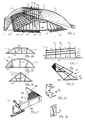
- Fig. 1 presents a perspective view of one of the favourable modes of application of equipment according to the invention, which consists of a drying frame, drying frame peripheral edge fittings, fan equipment at one end of the drying frame and a covering element to be spread over the rick on top of the drying frame in rainy weather,
- Figs 2a, 2b and 2c present several favourable modes of application of the support framework of the drying frame,
- Fig. 3 presents a longitudinal cross-sectional view of the drying frame according to Fig. 1,
- Fig. 4 presents a perspective view of a part of the longitudinal/horizontal edge fittings according to another favourable mode of application according to the invention, i.e. that is an edge-widening part suitable for widening the drying area,
- Fig. 5a and 5b present several favourable devices for fastening the edge-widening parts according to Fig. 4, with adjustable location to the supporting framework of the drying frame,
- Fig. 6 presents a perspective view of a part of the longitudinal/horizontal edge fittings according to a third favourable mode of application according to the invention, i.e. a walling structure for easing the location of the drying area wall, with which, in addition, the risk layer thickness can be increased, especially with easily overflowing materials, more than would otherwise be possible,
- Fig. 7 presents a covering device according to the invention fitted to the drying equipment, kept rolled up in reserve, to be rolled out when taken into use, in which figure the cover is rolled out for use and tied at one edge to the vertical post,
- Fig. 8 presents in perspective view part of the drying frame modules of the drying apparatus according to the invention,
- In Fig.9 is a detail view of the interlinking of module parts to one another, and
- Fig 10 presents the manner of mounting and installing the fan motor according to the invention and the mode of electrical installation.
- As can be seen from Figs 1 and 3 an equipment according to one favourable mode of application of the invention, primarily meant to be used in outside air, i.e. in field conditions and for the mechanical drying of organic fibre-based loose material, such as stalked materials, peat and wood chips etc, is formed of the drying
frame 1, which limits the the drying air flow hollow or dryingchannel 2 on the underside extending to the ground, which channel will in future here be referred to as the air duct, and which together with the dryingframe 1 and itsedge fittings 15 carries the material to be dried as an even layer heaped into a rick in such manner that the material to be dried and the ground 3 do not come into contact with each other. Further the equipment according to the invention for the mechanical drying and attainment of forced air flow fromair dust 2 through the material layer to outside air or conversely, from outer air through the material layer toair duct 2, includesfan unit 4, which is located in the end ofduct 2. In addition the drying equipment according to the invention optionally includes a coveringunit 5, to be used particularly in rainy weather and to be spread over the material layer to be dried to prevent its becoming wet. - As is evident from Fig 1 the
drying frame 1 according to this advantageous mode of application includes several vertical, most advantageously post-like,vertical elements 11, favourably located at intervals between 0.5 - 2 m from each other and set into the earth along the same line, the length of each vertical being favourably between 2.0-4.0 m and carrying at a distance from the ground, favourably 2.0-0.3 m, one, most favourably bar-like,horizontal element 12, the length of which is favourably between 2.0-0.5 m and to tile free end of whichelement 12 is attached through an angle slanting downward from the horizontal a flank-, most favourably a bar-like element 13, the free end of which is supported against the ground. The consequence of too steep an angle is the danger of the material to be dried spilling off the top of the hurdle frame, for which reason the angle in question is advantageously selected between 20 deg-60 deg arid most favourably about 30 degrees. Avertical element 11, ahorizontal element 12 and two flank elements compose in this mode of application one of the individual support frameworks of the drying frame on top of which the material intended for drying is heaped. In the application mode according to Figure 1 the base fittings leave openings between both thehorizontal elements 12, and located on top offlank elements 13 the longitudinal, favourably bar-like elements 14, favourably of slats, which extend either individually or fitted end to end in the direction of the flank element lengths, the opening size being selected each time depending on the size of the particles of the material to be dried and the length of thedrying element frame 1. - In order to prevent the material to be dried contacting the ground the drying frame includes at least a ground
contact prevention edge 15 accompanying the drying frame as an edge fitting that extends to the ground at least on the longitudional side,edge 15 being supported against the ground and on top of it is piled the material to be dried that comes closest to the ground surface. The edge part mentioned in the advantageos mode of application according to Fig 1 is formed of several favourably pole-like elements 151, which are fitted parallel to each other at a short distance, favourably 1.0 - 5.0 m and against the ground for their whole length when it can be ensured that no air leakage occurs underneath the rick, but that all the air intended for drying only flows through the material layer to be dried to outside air or into the air duct and the rick is isolated from ground moisture. - It is not fundamentally significant from the operational aspects of the invention here presented which material is used for the individual members of the
drying frame 1 or the groundmoisture prevention edge 15 nor how they are connected to each other. It can however be verified that suitable manufacturing materials for the elements are for example, wood, plastics and metal arid that favourably individual elements are fastened for example, with removable pin or bolt connection to one another, so that storage over the winter of the drying frame and of individual elements of the aforementioned edging parts can be in a warehouse without them taking up much space and the assembly of the elements to the desired size is fast and trouble-free, if the drying frame is made of wood slats, the individual slats, for example of scrap wood, can be nailed to one another. The simplest mode is however to construct the equipment according to the invention on a site where it can be kept assembled over the winter. - It is fundamentally important for the material to be dried from the evenness and drying point of view that the material can be laid evenly and particularly that its upper parts are fundamentally in an uncompacted layer on top of the drying frame, and also that the air flow and its drying efficiency remain as evenly distribued as possible through the rick material while the drying of the material progresses. In order to achieve these objectives the free ends of the pole-like
vertical elements 11 fundamentally project higher than the bar-likehorizontal elements 12 fastened onto them, when the free ends of the aforementionedvertical elements 11 function on the one hand in heaping up the material to be dried onto the drying frame and on the other hand as aids in evaluating the thickness layer of the rick of material to be dried and again as an aid in evaluating the longitudional centre line of the rick to be formed. Then as the result of mere visual inspection it is possible to verify with sufficient accuracy both the evenness of the rick layer thickness and the location of the material rick relative to the drying frame. In order to prevent compaction of the rick material compaction preventive elements, favourably bar-like elements vertical elements 11 in the direction of the drying frame longitudinal axis, favourably barlike compactionpreventive equipments longitudinal elements 14 of the drying frame and it thus compacting. - Further, in order to achieve the above objectives it is important that the drying efficiency of the drying air is as constant as possible over the whole length of the material rick. For this reason the
air duct 2 limited by the inside of the drying frame reduces in size starting from the end wherefan equipment 4 is located. In Fig. 3 is illustrated a favourable mode of application of a drying frame according to the invention, tapering towards its rear end. In a drying frame meant for the drying of hay and stalk-like material in general the height of the air duct reduces, i.e. by lowering the location of the horizontal element on the vertical element, favourably over a distance of 10 -20 m by half of the original height at the starting end or, the fan equipment sided Thus the pressure loss caused by the air flowing through the risk to outside can be compensated for and the pressure prevailing in the air duct is set to optimal for the material quantity at each point of the rick, which makes possible the progress of the drying front in all parts of the risk at fundamentally constant speed. - As can still further be verified from Fig. 1 the equipment according to the invention includes a
covering unit 5 for preventing the stalked material from becoming vet in rainy weather, which when not in use is kept rolled up and when taken into use is spread out over the risk. The covering unit in the favourable mode of application of Fig 1 is composed of two covering elements fitted on both the long sides of the dryingframe 1, for example oflight coverings 5, each of which are rolled up at the lover edge of dryingframe 1, favourably close to the dryingframe edge fittings 15, from which position they can be drawn out over the risk to be dried and fastened from the free long edge with suitable fastening devices, for example with the aid of straps, ropes or similar means, to thevertical elements 11, so that along the line passing through thevertical elements 11 is left a space between the longitudinal edges of thelight coverings 5, thegap 18 extending along the full length of the risk, through which the damp air can escape to the outside air. - There is cause to conclude in this connection that keeping the
light coverings 5 in roll is naturally not the only possible solution.Light coverings 5 can also be kept folded in store when not in use and fetched from there in time of rain and spread over the risk. Then, however, there is reason to reserve sufficient number of weight to hold the edges of the light coverings against the ground so that the wind cannot move the light covers off the rick. The application already mentioned before of a covering stored rolled up is presented in Fig 7 the advantage of which is an especially precise potential for utilisation of the weather condition. In this application therotation mechanism roll 51 is used as the removal and setting device of thecover 5, which is fitted to the lower edge of the rick flat, whereupon moving of the cover is carried out by dragging it along the risk material surface. There is reason to mention that the covering roll can naturally be located when not in use close to thevertical elements 11 and that the covering roll can be rolled upwards or downwards along the risk flat, then by setting the direction of rotation of the covering roll the selection of either baring the risk (cover rolling up) or covering the risk (cover spreading over) can be decided. In the mode of application according to Fig 7 the rotation mechanism in formed at the grooved end of coveringroll shaft 51 by using e.g. the known sprung-loaded, ball-locking, detachably connected power device which includes thelever arm 52 andratchet mechanism 53. As the power device in question other power devices, e.g. electrical or hydraulic power devices can naturally be used, the power output shaft of which, with suitable connection and power transmission, e.g. universal joint shaft, is connected to the covering roll shaft for its rotation
Although the matter has not been more accurately clarified above, the ends of the dryingframe 1 can also be furnished with end elements or slats similar toflank elements 13 and end edging parts similar to the ground moistureprevention edging parts 15. The drying frame is then enclosed on all of its sides and also the ends of the drying frame car, be used as a base for the material to be dried. Additionally for the covering of the rick ends, end covers similar to the light covers described above, the gathering and spreading of which can be carried out when necessary in the manner described above. - In Figs 2a, 2b and 2c some favourable shapes of
air duct 2 within the limitations of the drying frame are illustrated. The shape in Fig 2a is identical to that of the first favourable mode of application of the invention described in Fig 1 excluding the transverse strengthening orsupport element 19 in the base of the drying frame, the purpose of which is to stiffen the frame against the transverse direction of loading, and
theadditional support element 20 between the joining points of flank andhorizontal elements aforementioned support element 19. In the mode of application according to Fig 2b instead of thestraight element 12 and thestraight flank element 13 there is correspondingly a curved horizontal element 12' and a curved flank element 13', when a curving part, favourably of arced shape, is formed as part of the support frame of the drying frame with which it is possible to achieve the maximum circumferential area as the base of the material to be dried. In the mode of application according to Fig 2c the drying element is formed ofvertical element 11 and immediately to it are fastened one end of thestraight flank elements 13 and the stiffening or supportingelement 19 in the base of frame, a triangular frame being generally stiff. As can be further verified from Figs 2b and 2c the drying frame support frames according to these modes of application can be furnished with an additional supportingelement 20, such as in the mode of application in Fig 2b link the stiffening or supportingpart 19 and the joint of the horizontal element 12' and theflank element 13, such as in Fig 2c link together the strengthening or supportingelement 19 and theflank element 13. - When constructing the drying equipment according to the invention on site from stock pieces fundamentally into a form according to Fig 1 the
air duct 2 can also be dimensioned to accurately correspond to the needs in its breadth direction but if the support frames are made with standard, for example industrial, sizes similar fundamentally according to Figs 2a, 2b, 2c or 8 and if the attainment of even air over the whole rick length so requires, the drying frame can be furnished withedge fitting part 26 according to Fig 4, a part widening the edge of the drying area, which to advantage can be affixed steplessly in both breadth or height direction to the flank element of the drying frame support construction, and is thus intended to be located between the dryingframe 1 proper and the ground moistureprevention edge part 15. - As can be seen from the relevant Fig 4, the widening
edge part 26 according to this mode of application is made up ofelements 262 in the transverse direction relative to the longitudinal axis offrame 1, which elements can be of any material, most suitable wood or plastic, and in each of which edge parts are at least two pieces each connected to theflank element 13 where it reaches the ground, and theside element 263 running in the same direction relative to the longitudinal axis of thehurdle frame 1, each of whichelements 263 are fastened at least from both ends to thetransverse elements 262 where their free ends protrude fromhurdle frame 1. In addition as can be seen from Fig 4 theedge widening part 26 includes in this mode of application anet base 264, in place of which slatting may also be used, and the net opening (or slat spacing) of which is made suitable for each material to be dried, i.e., the net openings that may be used with hay are larger than, for example those for use with wood chips, so that the material cannot spill through the net (or slat) openings inside theedge widening part 26. Theedge widening part 26 according to this mode of application is fastened for an arrangement in the transverse direction to dryingframe 1, whereupon theedge widening part 26 can be set suitably for the layer thickness of each rick material, so that the outermost peripheral surface of the rick material layer does not extend to the outermostlongitudinal element 151 of the groundmoisture prevention part 15 to be fitted beside the edge widening part. A really thick rick layer can then be reliably isolated from the ground, and adverse air gaps are not created between ground and rick surfaces. - In Figs 5a and 5b two favourable fitments for fastening the
edge widening part 26 in place are presented. The locking fitment according to Figure 5a is formed of a generlly U-shaped metallic piece 6, the waist part of which is dimensioned to correspond to the height of thetransverse element 262 of the edge widening part, and inside which thetransverse element 262 is intended to fit. The forked parts of the U-piece then project beyond the transverse elements and in these forked parts are slots opening in opposite directions to each other and these are dimensioned to fit over theflank elements 13. When fitted in place to the transverse element, e.g. with the aid of screws, the slots support the flank elements in opposite directions and thus hold the transverse element as well as the whole of the edge widening part firmly in the desired place. By changing the position of the screw fastenings in the transverse element the whole position of theedge widening part 26 relative to dryingframe 1 is changed especially in the lateral direction, but also when needed in the vertical direction. In the mode of application according to Fig 5b the locking fitment 6' is made from a formed plate in which there is a depression made to correspond with the shape of theflank element 13 and the height of which is dimensioned to correspond to the respective height of thetransverse element 262. The locking fitment 6' according to this mode of application is used so that it is set over theflank element 13 and fastened, e.g., with screws in the desired place, whereupon the locking fitment 6' presses the flank element against thetransverse element 262 and keeps it securely in place in the desired position. As before, by changing the position of the screw fastening the whole position of the wideningedge part 26 relative to thedrying frame 1 is changed. - In Fig 6 a third edging part according to one favourable mode of application of the invention is presented, i.e. a
wall edging part 27, to be positioned in the direction of the longitudinal axis of dryingframe 1, as an outer part of the edging equipment. Thethird edging part 27 according to this mode of this application is formed of a slat frame, which is arranged for folding on its long edge along the side of the drying frame, when it has thefirst framework part 275 supported on the ground and thesecond framework 276 that is intended for support by the external surface of the rick. In addition this secondary mode of application includes at least onedevice 277 for the adjustment and locking of the angle of inclination between the first andsecond frameworks other framework part 276, and the other end of which is furnished with, for example, a drilled or perforated plate, so that the hole of the drilled or perforated plate is dimensioned to fit onto the pin-like protrudingparts 278 set apart at intervals, whereupon by changing the position of the other end of the adjustment and locking element in relation to the edge part of the first framework the angle of inclination of this third mode of edge part can be adjusted. As can be further seen from Fig 6 the third edging part acccording to this mode of application can, if so desired, be furnished with a net (or with slats), the net opening size of which is selected to suit the material to be dried so that the material cannot spill through the openings in the net (or slats) to the ground. - The third edging part according to Fig 6 is then favourably an airy wall part, the purpose of which is, especially when there are large quantities of material to he dried, ease in making the rick and ensuring that the rick is correct in relation to the drying frame and the air duct beneath it, and thus making possible an even material layer throughout and the ideal even throughflow of air and also even drying. With the aid of such a
wall edging part 27 the height of the rick in relation to its width can be greater than any natural spilling angle characteristic to the material would allow. On the merits of this effect it is possible to increase the rick height of easily spilling materials in ralation to its width, and as a further advantage, the shape of the air duct cross-section can be selected more freely. - Then the drying equipment according to the invention is thus formed of drying
frame 1 which supports on its upper side thebase fittings 14 for the material rick to be dried and limits on its lower side theair duct 2, to which is connected at least onefan device 4 for the creation of a drying air flow through the rick material layer, edge fittings, which consist of at least groundmoisture prevention part 15 andwall edging part 27, or alternatively anedge widening part 26, groundmoisture prevention part 15 andwall edging part 27, which edging parts keep the lowermost parts of the rick separated from the ground and especially thewall edging part 27 ensures correct location of the rick material relative toair duct 2, and an optionally used covering element, with which wetting of the rick is prevented if it rains. Thewall edging part 27 being jointed can if need be dropped and/or removed if for example the emptying technique of the dryer so requires. - In Fig 8 a favourable mode of industrially manufactured drying hurdle of modular construction is presented, in which the manufacturing materials are favourably of plastic and metal.
- As can be seen from Fig 8 the supporting framework 1' of the drying frame is formed of the first
transverse element 19 against the ground, and in rectangular cross-sectional form, and of the secondtransverse element 13, of circular arc form and of round cross-section, which is together with another transverse element in the same vertical plane, as well as several intermediate elements 11' connecting the transverse elements and supporting the support framework, round in cross-section, the central of which, i.e. the one fitted on the centreline of the drying frame, the central intermediate element 11', passes through the curved transverse element 13' for the continuation of which, most suitably with a sleeve-like connection, is the verticaladditional element 20, which functions as a marking device for the layer thickness and alignment of the rick material layer on top of the drying frame and also as a fastening support for the covering device spread over the material rick and is when necessary, for example when the dryer emptying technique so demands, easily removed from its sleeve or corresponding fastening. The drying frame 1' is stiffened in the longitudinal direction by aslanting supporting piece 28, which is fitted to connect the vertical intermediate support 11' and the stronglongitudinal support 22 of at the least two successive supporting frameworks. - As can be still further verified from Fig 8 in this mode of application the ends of the arched tranverse elements 13' are sunk directly into the straight
transverse element 19 near to its ends so that the ends of the straight transverse element are projecting for some war, favourably 10-40 cm outside the external circumference of the transverse elements 13'. - Such support frames 1' described above are suited for the formation of a drying frame with spaces between each other in the longitudinal axis direction and then supported at the relevant separation distance by
longitudional spacer elements 21, which are joined together most suitably by such a connection as is presented in Fig 9 or by some other easily installed and dismantled connection. This connection of thelongitudinal elements 21 and thetransverse element 19 has been so made that at one end of the longtudinal elements to be joined together there is a pin-like protrusion 23 and in the other end there is acorresponding opening 24 suited to fit around it. The projecting end of thetransverse element 19 is located in between the longitudinal elements to be joined together and for that reason theopening 25 is made in it through which theaforementioned protrusion 23 is fitted. Additionally in order to ensure the support of the supporting frames there is alongitudinal support 22 fitted to the ridge of the transverse curved elements of the drying frame in which there are several openings at a separation distance corresponding to the separation distances of the support frames which are arranged to fit over the end of the centralintermediate element 11 of the support frame protruding beyond the outer circumference of the curving transverse element in the manner shown in Fig 9. Furthermore the drying frame according to this mode of application includes a net element 14' as the base for the heaped rick material, with which thelongitudinal slatting 14 constructed on top of theflank element 13, as described in connection with Fig 1 at the beginning of this patent application, can be substituted. Such a net can be extended in one piece over the whole drying frame area or be made up of two net elements, one of which coveres one half of the drying frame and the other correspondingly the other half. Further it is important that the net opening size is selected to correspond to the particle size of the rick material to be dried so that no unnecessary spillage of the material into the air duct occurs. - When using the drying construction according to the invention the mechanical drying of the organic fibre-based loose material, such as stalked materials peat, chips and the like is performed as follows:
- the material to be dried is heaped on top of the upper side of the drying frame base fittings and the edge edge fittings, isolated from the ground surface for an even layer throughout, when marking aids projecting vertically upwards on the drying frame centreline, and optionally the outer wall edging parts included in the equipment edge fittings, are used as an aid,
- an airflow is set up in the air duct formed by the limitung underside of the drying frame, which is closed and is furnished at least at one end with a fan device, which airflow is in the beginning directed either from the air duct through the rick to outside air, or conversely from outside air through the rick to the air duct - for example on the vacuum principle whereupon air in the air duct is taken by the fan equipment from the air duct to outside air,
- during the rick drying period the direction of the air flow through the rick layer is changed, so that in irregular weather the fan can be use to advantage on the pressurised operation principle with the covering equipment spread out, but in reliably fine weather the covering equipment can be removed and the solar energy directed onto the rick can be utilized to the maximum and by occasionally using the fan in suction mode the heat energy can be utilized for drying deeper than the top surface layer and different moisture levels in the material layer can be evened out. With large quantities of material, for example in district heating station peat and chip consumption, it might he necessary to use two
fan equipments 4 which can then be located in the opposite ends of the drying equipment, when the drying frame with its edge fittings is formed in two corresponding opposing halves relative to the transverse symmetrical axis, finally - the dried material is collecte together either for storage or further processing or it can he stored by the drying equipment until it will be utilised.
- According to one favourable mode of application of the invention the
fan equipment 4 includes a power drive device, favourably an electric motor and its driven rotor, as well as the support frame surrounding the rotor and the inblowing and/or outblowing flow duct that is fitted as the continuation of the support frame, the duct being directly connected toair duct 2 limited by the lower side of dryingframe 1, whence the only path to the outside air is through the fan equipment or through the rick' when the path of the forced airflow from the fan duct throughair duct 2 to outside air or conversely from outside air throughair duct 2 to the fan duct only passes through the rick material to be dried. How the fan duct is connected to the air duct limited by the drying frame l is not fundamental from the invention aspects but it is, however, advantageous that the connection is made as air-tight as possible, whereupon it is advantageous that the air duct projects some distance inside the dryingframe 1 and that the end of the drying frame on thefan equipment 4 side is furnished with slanting vertical elements on top of which the material to be dried is set. Naturally fully enclosed end elements, for example of plastic sheet, can be used, in which there is an opening dimensioned to correspond to the fan duct dimensions. - When an electric motor is used as the power device in the
fan equipment 4 it is advantageous that the mounting of thefan motor 41 and theelectrical installations 43 are so fashioned that the attachment of thesupport frame 46 to thefan duct casing 42 is performed withbolts 44 or by quickly locking catches, and that theelectrical switches 43, i.e. the star-delta safety switch, the switch to change the direction of rotation and the electrical power plug are mounted onto theaforementioned support frame 43, whereupon the fan equipment can be transferred as a complete unit with the aid ofsupport frame 43 to another operational site. It is then possible to manufacture the fan motor/electrical switch combination industrially and thanks to the direction of rotation switch the the fan blowing direction can be changed in order to even out moisture differences and utilize the weather conditions to the optimun so as to speed up the drying. - The invention is only described above by exemplification with the aid of some favourable modes of application. The purpose in this is not to limit the invention but only to illustrate the wide possibilities of the ingenious basic perception of the invention. Thus, as will be clear to the professional person in this field, the invention can be varied to a remarkable degree in its constructional details and general appearance within the boundaries of the accompanying patent claims. In particular it should be noted that with large quantities of material it is necessary to use two fans which can be located at opposite ends of the drying equipment and then construct the drying equipment in two halves, which are mirror images of each other, and which could be separated from each other with an intermediate wall.
Claims (20)
- An apparatus for the drying in open air of organic fibre-based loose materials such as straw materials, peat and wood chips, comprising;
an elongate drying frame (1) for carrying on its upper side in rick form the material to be dried, the drying frame forming with the ground (3) an air-flow duct (2);
the drying frame (1) comprising at least two generally planar supporting frames (11, 12, 13, 13'), the supporting frames extending transversely of the longitudinal axis of the drying frame (1); the supporting frames being linked together by longitudinal elements to define the elongate drying frame and the air-flow duct therewithin;
edge fittings (15, 26, 27) extending in the direction of the longitudinal axis of the drying frame (1) adjacent longitudinal edges thereof;
a plurality of vertical elements (11, 20) aligned along the longitudinal axis of the drying frame (1) so that material to be heaped on the drying frame is heaped about said vertical elements;
upper fittings (16, 17) extending longitudinally along the top of the drying frame (1) adjacent the vertical elements (11, 20) for reduction of compaction in the material rick formed;
characterised in that
the apparatus is a mechanical dryer having fan means (4) provided at least at one end of said air flow duct (2) for the creation of a forced air flow in said duct (2);
the vertical elements (11, 20) are indicator elements aligned along the longitudinal axis of the drying frame and extending a sufficient distance above the supporting frames to project through the layer thickness of material to be heaped on the drying frame to indicate the layer thickness and also to indicate the alignment of the material rick to be formed in relation to the longitudinal axis of the drying frame (1);
the edge fittings being arranged to support the material rick clear of the ground surface and to inhibit air-flow leakage through the intermediate space between the material rick and the ground whereby the air-flow caused by said fan means (4) is directed preferentially through the material of the rick;
and a covering means (5) for covering the material rick and affording an air gap above the rick for allowing passage of damp air. - Apparatus as claimed in claim 1 wherein said upper fittings (16, 17) are formed of at least two elongate elements extending longitudinally of the drying frame and secured to said vertical elements (11, 20).
- Apparatus according to claim 1 or 2 wherein the air flow duct (2) narrows in the longitudinal direction of the drying frame away from said fan means.
- Apparatus according to any of claims 1 to 3 wherein the edge fittings comprise a plurality of substantially parallel elongate elements (151) serving as dampness prevention members, each of which contacts the ground for closing the space between the material rick and the ground surface and directing the forced air-flow through the material.
- Apparatus according to claim 4 wherein said edge fittings comprise an outermost wall edging means (27), supported on the ground and fitted immediately adjacent the dampness prevention members (15),
wherein said wall edging means comprises:
a slat framework having a first, lower frame (275) supported on the ground and a second, upper frame extending from said lower frame for supporting against the material stack outside perimeter said upper frame having a net for the passage of air; and
a locking element (277) for the adjustment and locking of the angle between the first and the second frames. - Apparatus as claimed in claim 5 wherein said locking element (277) is pivotally connected to said first frame and is connectable to said second frame by a pin.
- Apparatus according to any of claims 1 to 6 wherein the edge fittings comprise:
edge widening means (26) fitted immediately adjacent the longitudinal edges of the frame against the ground for extending the drying area, the edge widening means comprising a frame open to the air duct (2), and having at least one longitudinal frame element (263) and at least two transverse elements (262) secured to the ends of said longitudinal frame elements;
and wherein said frame elements (262, 263) are each against the ground and carry on an upper side thereof a base means (264) for allowing passage of air-flow through the material stack. - Apparatus according to claim 7 wherein said base means (264) is formed by a net or a plurality of slats.
- Apparatus according to any of claims 1 to 8 wherein the covering means comprises at least two covering elements (5) each of which is moveable from a first position adjacent said vertical elements to a second position whereby said covering element covers a respective supporting frame (11, 12, 13, 13'); and wherein said covering elements are provided along their adjacent longitudinal edges with fastening means for securing the covering elements to the vertical elements (11, 20) to form a gap (18) between the covering elements for allowing escape of damp air.
- Apparatus according to claim 9 wherein said fastening means comprises straps or ropes.
- Apparatus according to claim 9 or 10 wherein said covering elements are stored on respective roll means and further comprising drive means for rolling and unrolling said covering means.
- Apparatus according to claim 11 wherein said drive means comprises a manually operable lever arm (52) or an electric or hydraulic motor detachably connectable to a centre shaft (51) of said roll means.
- Apparatus according to any of claims 1 to 12 wherein said fan means comprises a rotor support frame (46) detachably secured by securing means (44) to a fan duct (42) which is in turn coupled to the flow duct (2); and wherein furnishings and electrical connections (43) for the fan means are secured relative to said support frame (43) for movement with the support frame.
- Apparatus according to any of claims 1 to 13 wherein said fan means has an electric drive motor and switch means for controlling the direction of rotation of said motor for changing the direction of flow of air through said air-flow duct (2).
- Apparatus according to any of claims 1 to 14 wherein said drying frame has end supporting frames for supporting said generally planar supporting frames and wherein each said supporting frame is modular in construction;
wherein each said end supporting frame has a first, generally straight element (19) for contacting the ground and a second, generally curved element (13') lying in substantially the same vertical plane as said first element (19), and a plurality of intermediate elements (11) interconnecting said first and second elements;
and wherein said end supporting frames are interconnected by longitudinal elements (21, 22) extending substantially parallel to the longitudinal axis of the drying frame, one of said longitudinal elements interconnecting said first elements (19) and a second of said longitudinal elements interconnecting said second elements (13') substantially at their uppermost point, and further angled elements (28) interconnecting said intermediate elements (11') and said second longitudinal element (22) substantially along the centre line of the drying frame. - Apparatus according to any of claims 1 to 15 comprising at least two fan means (4) located at opposite ends of the drying frame and wherein said drying frame comprises two halves arranged on respective sides of an axis of symmetry.
- A method for mechanical drying in open air of an organic fibre-based material such as straw material, peat or wood chips, using a drying frame according to any one of claims 1 to 16, the method comprising:
heaping the material to be dried on top of the drying frame along the drying frame to form a rick spaced from the ground;
ensuring that the material is of a uniform layer thickness along said drying frame by comparing the outer surface of the heap of loose material with said vertically projecting elements (11, 11', 20) and said edge fittings (15, 27); and creating an air-flow through the material on the drying frame, by operation of the fan means. - A method according to claim 17 further characterised in that the fan means are operated alternately in opposite directions so as to change the direction of flow of air through the heaped material rick.
- A method as claimed in claim 17 or claim 18 further comprising sealing the intermediate space between the rick under surface and the ground surface for preventing airflow leakage past said edge fittings.
- A method as claimed in any one of claims 17 to 19 further comprising covering said rick with a covering means (5) for protecting said rick from rain, said covering means being spaced from said rick material to provide a gap between said covering means on said rick material for the passage of damp air.
Priority Applications (1)
| Application Number | Priority Date | Filing Date | Title |
|---|---|---|---|
| AT87904876T ATE115618T1 (en) | 1987-07-07 | 1987-07-07 | DEVICE AND METHOD FOR MECHANICAL DRYING OF AN ORGANIC FIBER MATERIAL SUCH AS STRAW, PEAT, WOOD CHIPS AND OTHERS. |
Applications Claiming Priority (1)
| Application Number | Priority Date | Filing Date | Title |
|---|---|---|---|
| PCT/FI1987/000093 WO1989000185A1 (en) | 1987-07-07 | 1987-07-07 | A method and apparatus for mechanical drying of an organic fibre based material as straw materials, peat, wooden chips and the like |
Publications (2)
| Publication Number | Publication Date |
|---|---|
| EP0430933A1 EP0430933A1 (en) | 1991-06-12 |
| EP0430933B1 true EP0430933B1 (en) | 1994-12-14 |
Family
ID=8556423
Family Applications (1)
| Application Number | Title | Priority Date | Filing Date |
|---|---|---|---|
| EP87904876A Expired - Lifetime EP0430933B1 (en) | 1987-07-07 | 1987-07-07 | A method and apparatus for mechanical drying of an organic fibre based material as straw materials, peat, wooden chips and the like |
Country Status (5)
| Country | Link |
|---|---|
| EP (1) | EP0430933B1 (en) |
| DE (1) | DE3750882T2 (en) |
| FI (1) | FI895794A0 (en) |
| RU (1) | RU1836563C (en) |
| WO (1) | WO1989000185A1 (en) |
Cited By (5)
| Publication number | Priority date | Publication date | Assignee | Title |
|---|---|---|---|---|
| WO2006024463A1 (en) | 2004-08-27 | 2006-03-09 | Technische Universität Dresden | Method for drying biomass |
| DE202011105149U1 (en) | 2011-08-30 | 2011-11-24 | Matthias Penkert | baseplate |
| CN106440694A (en) * | 2016-11-15 | 2017-02-22 | 丹阳正联知识产权运营管理有限公司 | Fully-automatic rainproof type outdoor airing device |
| CN106440693A (en) * | 2016-11-14 | 2017-02-22 | 丹阳正联知识产权运营管理有限公司 | Rainproof outdoor airing device |
| CN106766738A (en) * | 2016-11-15 | 2017-05-31 | 丹阳正联知识产权运营管理有限公司 | Drying device outside liftable regulation rain-proof type room |
Families Citing this family (6)
| Publication number | Priority date | Publication date | Assignee | Title |
|---|---|---|---|---|
| FI890041A (en) * | 1989-01-05 | 1990-07-06 | Heikki Kalervo Oinas | SOLABSORPTION. |
| CA2430158A1 (en) * | 2003-05-30 | 2004-11-30 | Premier Horticulture Ltee | Peat moss harvesting and preparation process and the dryer used to carry out the process |
| FR3006859B1 (en) * | 2013-06-12 | 2016-02-26 | Barre Sas Ets | TOBACCO FOOT SUSPENSION CHASSIS |
| EP3384220B1 (en) * | 2015-12-01 | 2020-08-05 | Stora Enso Oyj | Method for drying a biomass pile |
| CN106927157A (en) * | 2017-04-11 | 2017-07-07 | 合肥富通环保新能源科技有限公司 | A kind of method that silo stores wheat temporarily |
| CN110425840B (en) * | 2019-08-27 | 2021-04-16 | 潍坊晨禾信息科技有限公司 | Traditional chinese medicine optic fibre magnetic force drying device |
Family Cites Families (5)
| Publication number | Priority date | Publication date | Assignee | Title |
|---|---|---|---|---|
| GB245971A (en) * | 1925-03-16 | 1926-01-21 | John Albert Frost | Improvements in or relating to means for ventilating or drying hay or corn stacks |
| GB613162A (en) * | 1946-06-13 | 1948-11-23 | Alexander Proctor | Improvements in or relating to the conditioning of hay and similar cut crops |
| US2859683A (en) * | 1954-12-23 | 1958-11-11 | Nat Steel Corp | Ventilating tunnel |
| DE1079879B (en) * | 1958-07-03 | 1960-04-14 | Voith Gmbh J M | Plant and method for drying and ventilating hay or the like. |
| DE1143357B (en) * | 1959-03-03 | 1963-02-07 | Franz Lothar Oberhofer | Scaffolding for opening agricultural products to be dried, such as hay, grain or the like. |
-
1987
- 1987-07-07 DE DE3750882T patent/DE3750882T2/en not_active Expired - Fee Related
- 1987-07-07 WO PCT/FI1987/000093 patent/WO1989000185A1/en active IP Right Grant
- 1987-07-07 EP EP87904876A patent/EP0430933B1/en not_active Expired - Lifetime
-
1989
- 1989-12-04 FI FI895794A patent/FI895794A0/en not_active IP Right Cessation
-
1990
- 1990-01-05 RU SU904742848A patent/RU1836563C/en active
Cited By (6)
| Publication number | Priority date | Publication date | Assignee | Title |
|---|---|---|---|---|
| WO2006024463A1 (en) | 2004-08-27 | 2006-03-09 | Technische Universität Dresden | Method for drying biomass |
| DE202011105149U1 (en) | 2011-08-30 | 2011-11-24 | Matthias Penkert | baseplate |
| CN106440693A (en) * | 2016-11-14 | 2017-02-22 | 丹阳正联知识产权运营管理有限公司 | Rainproof outdoor airing device |
| CN106440694A (en) * | 2016-11-15 | 2017-02-22 | 丹阳正联知识产权运营管理有限公司 | Fully-automatic rainproof type outdoor airing device |
| CN106766738A (en) * | 2016-11-15 | 2017-05-31 | 丹阳正联知识产权运营管理有限公司 | Drying device outside liftable regulation rain-proof type room |
| CN106766738B (en) * | 2016-11-15 | 2019-02-15 | 丹阳正联知识产权运营管理有限公司 | Liftable adjusts tanning device outside rain-proof type room |
Also Published As
| Publication number | Publication date |
|---|---|
| DE3750882T2 (en) | 1995-08-17 |
| RU1836563C (en) | 1993-08-23 |
| FI895794A0 (en) | 1989-12-04 |
| DE3750882D1 (en) | 1995-01-26 |
| WO1989000185A1 (en) | 1989-01-12 |
| EP0430933A1 (en) | 1991-06-12 |
Similar Documents
| Publication | Publication Date | Title |
|---|---|---|
| EP0430933B1 (en) | A method and apparatus for mechanical drying of an organic fibre based material as straw materials, peat, wooden chips and the like | |
| US3765134A (en) | Construction of rigid tensioned frame structure | |
| MX2014001300A (en) | Retractable roof. | |
| KR102155585B1 (en) | top, bottom, left, and right rotary type frost preventive fan apparatus | |
| US4915022A (en) | Vent assemblies | |
| CN104620903B (en) | Large span aeration type heliogreenhouse | |
| CN105746235A (en) | Sunlight greenhouse adaptive to climates of south of China | |
| US5410844A (en) | Building vent assembly | |
| CN207054402U (en) | One kind adult cowshed | |
| CN104642004A (en) | Ventilation type sunlight greenhouse | |
| GB2024588A (en) | Protective enclosure | |
| CN111165192B (en) | Forced positive and negative pressure mechanical ventilation dry ear bin and use method | |
| CN204518659U (en) | Large span aeration type greenhouse by solar heat | |
| CA1148741A (en) | Method and apparatus for retaining heat in greenhouse and similar structures | |
| CN2404844Y (en) | Granary | |
| US2641988A (en) | Farm building | |
| CN208269536U (en) | It closes a position corn ear dryer | |
| KR20210034234A (en) | Multi-stage framed frame joining structure for vinyl house | |
| CN205755982U (en) | A kind of multifunctional intellectual room cultivated for Oryza glutinosa and dry storage | |
| KR102302133B1 (en) | Drying apparatus | |
| CN113383664B (en) | Wind, snow and heavy rain resistant and efficient ventilation film greenhouse building and use method thereof | |
| KR200497523Y1 (en) | one body type ridge clamp for assembling and constructing lightweight greenhouse | |
| FI79408C (en) | Process for processing straw or blast and container and dry k for carrying out the process | |
| CN208540527U (en) | Novel edible bacteria cultivation special plastic arched shed | |
| JPH0114663Y2 (en) |
Legal Events
| Date | Code | Title | Description |
|---|---|---|---|
| PUAI | Public reference made under article 153(3) epc to a published international application that has entered the european phase |
Free format text: ORIGINAL CODE: 0009012 |
|
| 17P | Request for examination filed |
Effective date: 19891219 |
|
| AK | Designated contracting states |
Kind code of ref document: A1 Designated state(s): AT BE CH DE FR GB IT LI LU NL SE |
|
| 17Q | First examination report despatched |
Effective date: 19911127 |
|
| GRAA | (expected) grant |
Free format text: ORIGINAL CODE: 0009210 |
|
| AK | Designated contracting states |
Kind code of ref document: B1 Designated state(s): AT BE CH DE FR GB IT LI LU NL SE |
|
| PG25 | Lapsed in a contracting state [announced via postgrant information from national office to epo] |
Ref country code: IT Free format text: LAPSE BECAUSE OF FAILURE TO SUBMIT A TRANSLATION OF THE DESCRIPTION OR TO PAY THE FEE WITHIN THE PRESCRIBED TIME-LIMIT;WARNING: LAPSES OF ITALIAN PATENTS WITH EFFECTIVE DATE BEFORE 2007 MAY HAVE OCCURRED AT ANY TIME BEFORE 2007. THE CORRECT EFFECTIVE DATE MAY BE DIFFERENT FROM THE ONE RECORDED. Effective date: 19941214 Ref country code: LI Effective date: 19941214 Ref country code: NL Effective date: 19941214 Ref country code: FR Effective date: 19941214 Ref country code: CH Effective date: 19941214 Ref country code: BE Effective date: 19941214 |
|
| REF | Corresponds to: |
Ref document number: 115618 Country of ref document: AT Date of ref document: 19941215 Kind code of ref document: T |
|
| REF | Corresponds to: |
Ref document number: 3750882 Country of ref document: DE Date of ref document: 19950126 |
|
| REG | Reference to a national code |
Ref country code: CH Ref legal event code: PL |
|
| EN | Fr: translation not filed | ||
| NLV1 | Nl: lapsed or annulled due to failure to fulfill the requirements of art. 29p and 29m of the patents act | ||
| PG25 | Lapsed in a contracting state [announced via postgrant information from national office to epo] |
Ref country code: LU Free format text: LAPSE BECAUSE OF NON-PAYMENT OF DUE FEES Effective date: 19950731 |
|
| PLBE | No opposition filed within time limit |
Free format text: ORIGINAL CODE: 0009261 |
|
| STAA | Information on the status of an ep patent application or granted ep patent |
Free format text: STATUS: NO OPPOSITION FILED WITHIN TIME LIMIT |
|
| 26N | No opposition filed | ||
| PGFP | Annual fee paid to national office [announced via postgrant information from national office to epo] |
Ref country code: DE Payment date: 19990720 Year of fee payment: 13 Ref country code: AT Payment date: 19990720 Year of fee payment: 13 |
|
| PGFP | Annual fee paid to national office [announced via postgrant information from national office to epo] |
Ref country code: GB Payment date: 20000615 Year of fee payment: 14 |
|
| PG25 | Lapsed in a contracting state [announced via postgrant information from national office to epo] |
Ref country code: AT Free format text: LAPSE BECAUSE OF NON-PAYMENT OF DUE FEES Effective date: 20000707 |
|
| PG25 | Lapsed in a contracting state [announced via postgrant information from national office to epo] |
Ref country code: DE Free format text: LAPSE BECAUSE OF NON-PAYMENT OF DUE FEES Effective date: 20010501 |
|
| PG25 | Lapsed in a contracting state [announced via postgrant information from national office to epo] |
Ref country code: GB Free format text: LAPSE BECAUSE OF NON-PAYMENT OF DUE FEES Effective date: 20010707 |
|
| GBPC | Gb: european patent ceased through non-payment of renewal fee |
Effective date: 20010707 |
|
| EUG | Se: european patent has lapsed | ||
| PGFP | Annual fee paid to national office [announced via postgrant information from national office to epo] |
Ref country code: SE Payment date: 20060705 Year of fee payment: 20 |