EP0430918A2 - Kammer eines Anzünders einer Patronenhülse - Google Patents
Kammer eines Anzünders einer Patronenhülse Download PDFInfo
- Publication number
- EP0430918A2 EP0430918A2 EP90870230A EP90870230A EP0430918A2 EP 0430918 A2 EP0430918 A2 EP 0430918A2 EP 90870230 A EP90870230 A EP 90870230A EP 90870230 A EP90870230 A EP 90870230A EP 0430918 A2 EP0430918 A2 EP 0430918A2
- Authority
- EP
- European Patent Office
- Prior art keywords
- anvil
- cylindrical
- central body
- envelope
- wings
- Prior art date
- Legal status (The legal status is an assumption and is not a legal conclusion. Google has not performed a legal analysis and makes no representation as to the accuracy of the status listed.)
- Withdrawn
Links
Images
Classifications
-
- F—MECHANICAL ENGINEERING; LIGHTING; HEATING; WEAPONS; BLASTING
- F42—AMMUNITION; BLASTING
- F42C—AMMUNITION FUZES; ARMING OR SAFETY MEANS THEREFOR
- F42C19/00—Details of fuzes
- F42C19/08—Primers; Detonators
- F42C19/10—Percussion caps
Definitions
- the present invention relates to a primer chamber for a central percussion firearm cartridge.
- a primer chamber consists of a bowl intended to receive the primer capsule and it is housed in the bottom of the cartridge case.
- a common type of primer chamber is made up of two parts: a cylindrical casing and an anvil intended to resist the impact of the percussion member of a firearm.
- the anvil is an integral part of the cylindrical envelope and the initiation chamber is made in one piece.
- the anvil has a body of tapered shape, conical or pyramidal for example, terminated by a flat end.
- the lower part of the anvil body, which is connected to the cylindrical envelope, is pierced with several vent holes arranged on the periphery of the anvil with a predetermined angular spacing between them. These vents are used to let pass the heat produced by the explosion of the primer under the effect of percussion in order to communicate it to the powder contained in the cartridge case to cause the propulsion of the projectile.
- the object of the present invention is to overcome the aforementioned shortcomings of the known initiation chambers and to produce an initiation chamber capable of transmitting sufficiently concentrated heat to the powder charge towards the center of the base of the sleeve so that the powder can ignite quickly.
- a primer chamber comprising an anvil which is an integral part of the cylindrical envelope, which primer chamber is remarkable in that the anvil has a flattened central body which extends parallel to an axial plane of the envelope, and in that the bottom of the cylindrical envelope on either side of the anvil has vent holes creating passages for the priming heat in the vicinity of the plane axial of the cylindrical envelope.
- the central body ends in two wings which have a tapered profile in their upper part and are connected to the top of the central body by forming a relatively flat end, the lower part of the wings being connected to the cylindrical envelope forming a part integral with it.
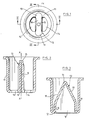
- Figure 1 is a plan view of an exemplary embodiment of the boot chamber according to the invention.
- Figure 3 is an axial section along line III-III of Figure 1.
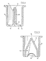
- FIGS. 4 and 5 represent an alternative embodiment of the priming chamber shown in FIGS. 1 to 3.
- FIG. 1 we see a cylindrical envelope 11 closed by a bottom 12 stamped to form an anvil 13 extending towards the inside of the envelope 11.
- the anvil B is formed with a central body 18 flattened extending parallel to an axial plane AA of the casing 11 (see FIG. 2).
- Two vents 14 are formed in the flat parts of the bottom which are connected to the cylindrical casing 11.
- the central body 18 ends in two wings 19 which have a tapered profile in their upper part (see FIG. 3) and are connected to the top of the central body 18 by forming a relatively flat end 15.
- the lower part 16 of the wings 19 is connected to the cylindrical casing 11 forming an integral part with this one.
- the drawing clearly shows that, thanks to the flattened shape of the anvil according to the invention, the vents 14 can be brought closer to the axial plane AA of the cylindrical envelope 11. They thus form passages for contiguous heat flows which concentrate the priming heat on the central part of the base of the socket containing the powder charge. This concentration of the heat imparted to the charge of the powder of a cartridge guarantees rapid ignition of the powder, which ensures that the projectile mounted in the head of the cartridge has an optimal propulsion speed.
- FIG. 4 An alternative embodiment of the priming chamber according to the invention is shown in Figures 4 and 5.
- the anvil 13 is identical to that shown in Figures 2 and 3.
- the part bottom of the central body 13A of the anvil has a cutout 17 which connects the vents 14 and thus forms a central vent hole for the priming heat, which adds to the effect of desired heat concentration.
Landscapes
- Engineering & Computer Science (AREA)
- General Engineering & Computer Science (AREA)
- Insertion Pins And Rivets (AREA)
- Surgical Instruments (AREA)
- Filtering Of Dispersed Particles In Gases (AREA)
- Portable Nailing Machines And Staplers (AREA)
- Refuge Islands, Traffic Blockers, Or Guard Fence (AREA)
- Toys (AREA)
Applications Claiming Priority (2)
| Application Number | Priority Date | Filing Date | Title |
|---|---|---|---|
| BE8901275A BE1003763A3 (fr) | 1989-11-29 | 1989-11-29 | Chambre d'amorce pour une cartouche d'arme a feu. |
| BE8901275 | 1989-11-29 |
Publications (2)
| Publication Number | Publication Date |
|---|---|
| EP0430918A2 true EP0430918A2 (de) | 1991-06-05 |
| EP0430918A3 EP0430918A3 (en) | 1991-11-21 |
Family
ID=3884411
Family Applications (1)
| Application Number | Title | Priority Date | Filing Date |
|---|---|---|---|
| EP19900870230 Withdrawn EP0430918A3 (en) | 1989-11-29 | 1990-11-28 | Primer chamber for a firearm cartridge |
Country Status (8)
| Country | Link |
|---|---|
| US (1) | US5148749A (de) |
| EP (1) | EP0430918A3 (de) |
| CN (1) | CN1027395C (de) |
| BE (1) | BE1003763A3 (de) |
| CA (1) | CA2031022A1 (de) |
| CS (1) | CS595590A3 (de) |
| RU (1) | RU1838752C (de) |
| ZA (1) | ZA909471B (de) |
Families Citing this family (1)
| Publication number | Priority date | Publication date | Assignee | Title |
|---|---|---|---|---|
| US6502514B1 (en) | 2001-09-12 | 2003-01-07 | Christopher A. Holler | Firearm cartridge having a plurality of ignition primer chambers and associated methods for reducing the likelihood of misfire and cold shot and enhancing rapid and reliable firing |
Family Cites Families (8)
| Publication number | Priority date | Publication date | Assignee | Title |
|---|---|---|---|---|
| IT628995A (de) * | ||||
| US932562A (en) * | 1907-08-26 | 1909-08-31 | Peters Cartridge Company | Shell. |
| US3195463A (en) * | 1962-07-19 | 1965-07-20 | Remington Arms Co Inc | Die cast battery cup and anvil |
| DE1932140A1 (de) * | 1969-06-25 | 1971-01-14 | Dynamit Nobel Ag | Patronenzuendung und Verfahren zu ihrer Herstellung |
| FR2214101A1 (de) * | 1973-01-12 | 1974-08-09 | Manuf Generale Munitions | |
| BE831139A (fr) * | 1975-07-08 | 1975-11-03 | Chambre d'amorce pour cartouche | |
| FR2355272A1 (fr) * | 1976-06-03 | 1978-01-13 | Manuf Gle Munitions | Dispositif d'amorcage pour munitions et analogues |
| US4315462A (en) * | 1979-09-10 | 1982-02-16 | Vollers Gary L | Shot gun shell primer |
-
1989
- 1989-11-29 BE BE8901275A patent/BE1003763A3/fr not_active IP Right Cessation
-
1990
- 1990-11-26 ZA ZA909471A patent/ZA909471B/xx unknown
- 1990-11-28 US US07/619,755 patent/US5148749A/en not_active Expired - Lifetime
- 1990-11-28 CN CN90109687A patent/CN1027395C/zh not_active Expired - Fee Related
- 1990-11-28 CA CA002031022A patent/CA2031022A1/en not_active Abandoned
- 1990-11-28 EP EP19900870230 patent/EP0430918A3/fr not_active Withdrawn
- 1990-11-28 RU SU4831789A patent/RU1838752C/ru active
- 1990-11-29 CS CS905955A patent/CS595590A3/cs unknown
Also Published As
| Publication number | Publication date |
|---|---|
| ZA909471B (en) | 1992-03-25 |
| EP0430918A3 (en) | 1991-11-21 |
| RU1838752C (ru) | 1993-08-30 |
| CN1054307A (zh) | 1991-09-04 |
| BE1003763A3 (fr) | 1992-06-09 |
| CN1027395C (zh) | 1995-01-11 |
| CS595590A3 (en) | 1992-03-18 |
| CA2031022A1 (en) | 1991-05-30 |
| US5148749A (en) | 1992-09-22 |
Similar Documents
| Publication | Publication Date | Title |
|---|---|---|
| EP1092939B1 (de) | Vorrichtung zum Befestigen eines Hülsenbodens an einer Treibladungshülse und Hülsenboden für eine solche Befestigungseinrichtung | |
| CA1333543C (fr) | Projectile destine a etre tire par une arme a feu | |
| LU84191A1 (fr) | Recipient pour boisson perforable par une paille | |
| CA2426840A1 (fr) | Dispositif et methode pour ameliorer l'extraction d'une substance alimentaire contenue dans un element de recharge | |
| FR2750206A1 (fr) | Projectile non letal | |
| FR2790079A1 (fr) | Projectile stabilise par un empennage et pouvant etre lance a partir d'un tube d'arme | |
| FR2578045A1 (fr) | Projectile perforant | |
| CA1054852A (fr) | Chambre d'amorce pour cartouche | |
| FR2932560A1 (fr) | Munition non letale. | |
| EP0430918A2 (de) | Kammer eines Anzünders einer Patronenhülse | |
| CA2103833C (fr) | Bombe d'artifice a combustion integrale | |
| FR2651283A1 (fr) | Rivet aveugle a explosion interne. | |
| KR20050096789A (ko) | 원스톱 차량번호 판 봉인장치 | |
| FR2507883A1 (fr) | Dispositif pour fixer une poignee a un ustensile culinaire et procede s'y rapportant | |
| EP4445792B1 (de) | Zweiteiliger ohrring mit optimiserten leitungsmittel von einem teil in den anderen | |
| EP0614065A1 (de) | Pyrotechnischer Gefechtskopf mit verbesserter Streuvorrichtung | |
| FR2777648A1 (fr) | Dispositif de neutralisation d'engins explosifs | |
| EP0310160B1 (de) | Antifahrzeug-Granate | |
| KR910700443A (ko) | 특히 반동이 없는 대전차 무기의 추진식 장약을 위한 점화장치 | |
| FR2754052A1 (fr) | Projectile d'exercice balistique | |
| EP0260245B1 (de) | Sprengbrandgeschoss | |
| EP2756258B1 (de) | Pyrotechnischer zünder | |
| FR2511765A1 (fr) | Munitions d'exercice | |
| FR2796456A1 (fr) | Systeme de declenchement selectif | |
| BE897449A (fr) | Obus |
Legal Events
| Date | Code | Title | Description |
|---|---|---|---|
| PUAI | Public reference made under article 153(3) epc to a published international application that has entered the european phase |
Free format text: ORIGINAL CODE: 0009012 |
|
| AK | Designated contracting states |
Kind code of ref document: A2 Designated state(s): DE ES FR GB IT |
|
| PUAL | Search report despatched |
Free format text: ORIGINAL CODE: 0009013 |
|
| AK | Designated contracting states |
Kind code of ref document: A3 Designated state(s): DE ES FR GB IT |
|
| 17P | Request for examination filed |
Effective date: 19920520 |
|
| 17Q | First examination report despatched |
Effective date: 19930402 |
|
| STAA | Information on the status of an ep patent application or granted ep patent |
Free format text: STATUS: THE APPLICATION IS DEEMED TO BE WITHDRAWN |
|
| 18D | Application deemed to be withdrawn |
Effective date: 19950808 |