EP0430833A2 - Lock for emergency exit with push bar - Google Patents
Lock for emergency exit with push bar Download PDFInfo
- Publication number
- EP0430833A2 EP0430833A2 EP90440002A EP90440002A EP0430833A2 EP 0430833 A2 EP0430833 A2 EP 0430833A2 EP 90440002 A EP90440002 A EP 90440002A EP 90440002 A EP90440002 A EP 90440002A EP 0430833 A2 EP0430833 A2 EP 0430833A2
- Authority
- EP
- European Patent Office
- Prior art keywords
- housing
- follower
- bolt
- board
- door
- Prior art date
- Legal status (The legal status is an assumption and is not a legal conclusion. Google has not performed a legal analysis and makes no representation as to the accuracy of the status listed.)
- Withdrawn
Links
- 230000000694 effects Effects 0.000 claims description 7
- 238000006073 displacement reaction Methods 0.000 claims description 4
- 230000000903 blocking effect Effects 0.000 claims description 3
- 230000003100 immobilizing effect Effects 0.000 claims 1
- 230000001788 irregular Effects 0.000 description 2
- 239000000779 smoke Substances 0.000 description 2
- 238000012986 modification Methods 0.000 description 1
- 230000004048 modification Effects 0.000 description 1
Images
Classifications
-
- E—FIXED CONSTRUCTIONS
- E05—LOCKS; KEYS; WINDOW OR DOOR FITTINGS; SAFES
- E05B—LOCKS; ACCESSORIES THEREFOR; HANDCUFFS
- E05B65/00—Locks or fastenings for special use
- E05B65/10—Locks or fastenings for special use for panic or emergency doors
- E05B65/1046—Panic bars
-
- E—FIXED CONSTRUCTIONS
- E05—LOCKS; KEYS; WINDOW OR DOOR FITTINGS; SAFES
- E05B—LOCKS; ACCESSORIES THEREFOR; HANDCUFFS
- E05B55/00—Locks in which a sliding latch is used also as a locking bolt
- E05B55/12—Locks in which a sliding latch is used also as a locking bolt the bolt being secured by the operation of a hidden parallel member ; Automatic latch bolt deadlocking mechanisms, e.g. using a trigger or a feeler
Definitions
- the present invention relates to the new industrial product that constitutes a security lock for an emergency exit with a push bar.
- the emergency exits of public premises are equipped with opening members, most often a push bar, which make it possible to open said exits in an emergency, so as to allow the rapid evacuation of the premises.
- opening members are quite frequently supplemented by an electric locking system controllable from a central station or by heat or smoke detectors, preventing irregular opening of the emergency exit in normal times.
- the opening members of most known emergency exits generally actuate the door bolt through locks which are most often affixed to the door leaf, and which have the drawback of being quite bulky.
- these opening members do not include means making it possible to lock them by means of a key which can also be operated from the outside, so that the emergency exits which they equip can only be opened from from inside the room, which is another disadvantage.
- the present invention aims to remedy these various drawbacks of known systems by providing a security lock which can be housed in the frame of the door of an emergency exit and which, while being maneuverable at any time by a bar has the advantage of being able to be locked using a key capable of being operated from outside the room.
- the security lock according to the invention thus comprises a set of means cooperating to allow on the one hand to block the bolt in the keeper of the amount of the door when the latter is closed and on the other hand to unlock said bolt, either from inside the room by means of a push bar, or from outside the room by means of a crutch engaged in a follower.
- the lock comprises a finger movable in horizontal translation projecting out of the headrest at a distance from the bolt, when the door is open and which re-enters the housing when the door is closed, actuating in its movement of removal of a set of two racks associated with a toothed wheel which cause the locking of the bolt, and therefore the locking of the door.
- the lock comprises a first follower maneuverable by the push bar of the door and the actuation of which causes the unlocking of the bolt, authorizing the opening of the door from inside the premises.
- the lock comprises a second nut which can be operated from the outside of the door by means of a crutch, the actuation of which also causes the unlocking of the bolt, authorizing the opening of the door of the outside.
- the lock comprises a double barrel which can be operated by a key either inside or outside the room, and whose actuation for locking the door causes the second nut to lock, preventing the door from being opened from outside the room, while allowing its opening from the inside by means of the push bar.
- the lock according to the invention comprises, in a housing 1, a bolt 2 mounted on a bolt tail 22 having approximately in its middle an L-shaped cutout 23 rounded at its two ends, the bolt tail 22 being mounted displaceable in translation on an approximately parallelepipedic support 24 provided with an oblong cut 25 approximately of the same dimensions as that of the L-shaped branch of the bolt tail 22 which is susceptible to overlap it.
- a spiral spring 26 secured to the housing 1 of the lock bears by its free end against the rear end of the bolt tail 22, so as to hold the bolt 2 in position outside the housing 1 of the lock.
- the support 24 is provided at its base with a cutout allowing passage to a board 3 which is provided with two lugs, one 31 positioned at its upper end and the other 32 a short distance below the tail of bolt 22, and which is on the other hand secured to a rod 33 which projects out of the cutout 25 of the support 24 and of the cutout 23 of the bolt tail 22.
- the plate 3 also comprises, in the vicinity of its lower end, a rack cutout 34 on which engages a toothed wheel 4 which also comes into engagement with a rack 51 cut out on a slider 5 held by two guide fingers 53 and terminated by a rim 52 crossed by an axis 61 integral with a finger 6 which projects out of the faceplate 11 of the lock, a spring 62 being interposed between the finger 6 and the rim 52, that the movement of the cursor 5 can come apply against a stop 54 secured to the housing 1.
- the board 3 is also provided with a finger-shaped protuberance 35, a spring 36 being positioned between this protrusion and a finger 37 secured to the housing 1.
- a short distance from the upper lug 31 of the board 3 is positioned a follower 7, mounted swiveling in the housing 1 and comprising an arm 71 and an axial bore 72 with square section intended to receive the operating rod of a push bar.
- the follower 7 is provided with a step 73 capable of moving inside a cutout 74 in an arc formed in the housing 1, on the side of the follower 7 opposite the board 3.
- a second follower 8 is mounted journalling in the housing 1, a short distance from the lug 32 of the board 3, being provided with an arm 81, an axial bore 83 with a square section and d a step 82 likely to move inside a cutout 84 in an arc formed in the housing 1, on the side of the follower 8 opposite the bolt tail 22, a thrust spring 85 bearing on the rear wall of the housing 1 completing the follower 8.
- the follower 8 finally comprises an angular projection 86 diametrically opposite the arm 81, capable of abutting on a movable stop 93 secured to a movable part 92 capable of being moved in vertical translation by operation of a key in a double barrel 9 mounted in the housing 1, a rotary part 91 secured to this barrel which can come into engagement with the movable part 92 which for this purpose has a re-entrant part 94 capable of being moved in horizontal translation in a housing 96 under the effect of the thrust exerted by the rotating part 91, freeing up a space where the end of the rotating part 91 is inserted, which drives the moving part 92 in vertical translation, which transmits its movement, via an arm 95, to the moving stop 93
- a spring 97 disposed in the housing 96 allows the re-entrant part 94 to return to its initial position when the rotary part 91 has completed a complete rotation.
- the operation of the lock according to the invention is as follows: when the door of the emergency exit is closed, the bolt 2 momentarily enters the housing 1 of the lock, with the bolt tail 22, blocking the rod 33 in position A. At the same time, the finger 6 enters the housing, driving the cursor 5 in translation and compressing the spring 62 against the rear edge 52 of said cursor 5.
- the finger 6 When the door is closed, the finger 6 remains tucked into the housing 1, its free end in abutment against the edge 13 of the door jamb 14, while the bolt 2 leaves the housing 1 to enter the keeper 12 arranged opposite in the upright 14 of the door, releasing the rod 33.
- the slider 5 Under the effect of the spring 62, the slider 5 moves in translation, its rack 51 in turn driving in translation the plate 3 via the toothed wheel 4 and the rack 34 of the board 3, the rod 33 of which moves to position B.
- the operation of the key in effect drives in rotation the rotary part 91 which drives in upward translation the movable part 92, which secured to the arm 95 also drives in abutment translation the stop 93 which comes in position D (see FIG. 3 ), in the immediate vicinity of the projection 86 of the follower 8.
- the actuation of the push bar continues to authorize the opening of the door from inside the premises, the follower 7 being able to be actuated freely.
- the lock according to the invention thus makes it possible to choose, in all desirable security conditions, the mode of opening of the emergency exit, which constitutes a notable advantage compared to existing locks.
- the lock can be supplemented by an electric locking system controllable from a central station or by heat or smoke detectors, so as to prevent the irregular opening of the emergency exit in normal times.
Landscapes
- Business, Economics & Management (AREA)
- Emergency Management (AREA)
- Casings For Electric Apparatus (AREA)
- Lock And Its Accessories (AREA)
Abstract
Serrure pour issue de secours à barre de poussée.Lock for emergency exit with push bar.
Cette serrure comporte un doigt (6) mobile en translation horizontale, faisant saillie hors de la têtière (11) de la serrure, lorsque la porte est ouverte et rentrant dans le boîtier (1) lorsque la porte est fermée, actionnant dans ce mouvement un jeu de deux crémaillères (34, 51) associées à une roue dentée (4) qui entraînent le blocage du pène, et donc le verrouillage de la porte, laquelle peut être alors ouverte soit au moyen de la barre de poussée actionnant un premier fouillot (7), soit au moyen d'une béquille manoeuvrant de l'extérieur un second fouillot (8), cette dernière manoeuvre pouvant être empêchée par un verrouillage de la porte réalisé au moyen d'une clé introduite dans un double barillet (9).This lock comprises a finger (6) movable in horizontal translation, projecting from the faceplate (11) of the lock, when the door is open and re-entering the housing (1) when the door is closed, actuating in this movement a set of two racks (34, 51) associated with a toothed wheel (4) which cause the locking of the bolt, and therefore the locking of the door, which can then be opened either by means of the push bar actuating a first follower ( 7), or by means of a crutch maneuvering from the outside a second follower (8), this latter maneuver being able to be prevented by locking the door produced by means of a key inserted in a double barrel (9).
Description
La présente invention a pour objet le produit industriel nouveau que constitue une serrure de sécurité pour issue de secours à barre de poussée.The present invention relates to the new industrial product that constitutes a security lock for an emergency exit with a push bar.
Les issues de secours des locaux publics sont munies d'organes d'ouverture, le plus souvent une barre de poussée, qui permettent d'ouvrir lesdites issues en cas d'urgence, de manière à autoriser l'évacuation rapide des locaux. Ces organes d'ouvertures sont assez fréquemment complétés par un système de verrouillage électrique commandable à partir d'un poste central ou par des détecteurs de chaleur ou de fumée, interdisant l'ouverture irrégulière de l'issue de secours en temps normal.The emergency exits of public premises are equipped with opening members, most often a push bar, which make it possible to open said exits in an emergency, so as to allow the rapid evacuation of the premises. These opening members are quite frequently supplemented by an electric locking system controllable from a central station or by heat or smoke detectors, preventing irregular opening of the emergency exit in normal times.
Les organes d'ouverture de la plupart des issues de secours connues actionnent généralement le pène de la porte au travers de serrures qui sont le plus souvent apposées sur le battant de la porte, et qui présentent l'inconvénient d'être assez volumineuses.The opening members of most known emergency exits generally actuate the door bolt through locks which are most often affixed to the door leaf, and which have the drawback of being quite bulky.
Par ailleurs ces organes d'ouverture ne comportent pas de moyens permettant de les verrouiller au moyen d'une clé susceptible d'être manoeuvrée également de l'extérieur, en sorte que les issues de secours qu'ils équipent peuvent être uniquement ouvertes à partir de l'intérieur du local, ce qui constitue un autre inconvénient.Furthermore, these opening members do not include means making it possible to lock them by means of a key which can also be operated from the outside, so that the emergency exits which they equip can only be opened from from inside the room, which is another disadvantage.
La présente invention a pour but de remédier à ces divers inconvénients des systèmes connus en proposant une serrure de sécurité qui peut être logée dans le bâti de la porte d'une issue de secours et qui, tout en étant manoeuvrable à tout moment par une barre de poussée, présente l'avantage de pouvoir être verrouillée à l'aide d'une clé susceptible d'être manoeuvrée de l'extérieur du local.The present invention aims to remedy these various drawbacks of known systems by providing a security lock which can be housed in the frame of the door of an emergency exit and which, while being maneuverable at any time by a bar has the advantage of being able to be locked using a key capable of being operated from outside the room.
La serrure de sécurité selon l'invention comprend ainsi un ensemble de moyens coopérant pour permettre d'une part de bloquer le pène dans la gâche du montant de la porte lorsque celle-ci est fermée et d'autre part de débloquer ledit pène, soit de l'intérieur du local au moyen d'une barre de poussée, soit de l'extérieur du local au moyen d'une béquille engagée dans un fouillot.The security lock according to the invention thus comprises a set of means cooperating to allow on the one hand to block the bolt in the keeper of the amount of the door when the latter is closed and on the other hand to unlock said bolt, either from inside the room by means of a push bar, or from outside the room by means of a crutch engaged in a follower.
Selon une caractéristique de l'invention, la serrure comprend un doigt mobile en translation horizontale faisant saillie hors de la têtière à distance du pène, lorsque la porte est ouverte et qui rentre dans le boîtier lorsque la porte est fermée, actionnant dans son mouvement de retrait un jeu de deux crémaillères associées à une roue dentée qui entraînent le blocage du pène, et donc le verrouillage de la porte.According to a characteristic of the invention, the lock comprises a finger movable in horizontal translation projecting out of the headrest at a distance from the bolt, when the door is open and which re-enters the housing when the door is closed, actuating in its movement of removal of a set of two racks associated with a toothed wheel which cause the locking of the bolt, and therefore the locking of the door.
Selon une autre caractéristique de l'invention, la serrure comprend un premier fouillot manoeuvrable par la barre de poussée de la porte et dont l'actionnement provoque le déblocage du pène, autorisant l'ouverture de la porte de l'intérieur du local.According to another characteristic of the invention, the lock comprises a first follower maneuverable by the push bar of the door and the actuation of which causes the unlocking of the bolt, authorizing the opening of the door from inside the premises.
Selon une autre caractéristique de l'invention, la serrure comprend un second fouillot manoeuvrable de l'extérieur de la porte au moyen d'une béquille dont l'actionnement provoque également le déblocage du pène, autorisant l'ouverture de la porte de l'extérieur.According to another characteristic of the invention, the lock comprises a second nut which can be operated from the outside of the door by means of a crutch, the actuation of which also causes the unlocking of the bolt, authorizing the opening of the door of the outside.
Selon une autre caractéristique de l'invention, la serrure comprend un double barillet manoeuvrable par une clé indifféremment de l'intérieur ou de l'extérieur du local, et dont l'actionnement en vue du verrouillage de la porte entraîne le blocage du second fouillot, interdisant l'ouverture de la porte de l'extérieur du local, tout en autorisant son ouverture de l'intérieur au moyen de la barre de poussée.According to another characteristic of the invention, the lock comprises a double barrel which can be operated by a key either inside or outside the room, and whose actuation for locking the door causes the second nut to lock, preventing the door from being opened from outside the room, while allowing its opening from the inside by means of the push bar.
Ces différentes caractéristiques de la serrure selon l'invention, ainsi que d'autres, ressortiront de la description qui suit d'un de ses modes de réalisation représenté sur le dessin annexé et fourni à titre purement illustratif, étant bien entendu que cette description ne présente aucun caractère limitatif vis-à-vis de l'invention.These various characteristics of the lock according to the invention, as well as others, will emerge from the description which follows of one of its embodiments shown in the appended drawing and provided for purely illustrative purposes, it being understood that this description does not has no limiting character with respect to the invention.
Dans le dessin annexé:
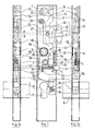
- - la figure 1 représente une vue de dessus de la serrure selon l'invention en position d'ouverture de la porte.
- - la figure 1a représente une vue latérale de la même serrure dans la même position, vue du côté de la têtière.
- - la figure 1b représente une vue latérale de la même serrure dans la même position, vue du côté opposé à la têtière.
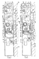
- - la figure 2 représente une vue de dessus de la même serrure en position de fermeture simple.
- - la figure 3 représente une vue de dessus de la même serrure en position de fermeture verrouillée.
- - Figure 1 shows a top view of the lock according to the invention in the open position of the door.
- - Figure 1a shows a side view of the same lock in the same position, seen from the side of the headrest.
- - Figure 1b shows a side view of the same lock in the same position, viewed from the side opposite the headrest.
- - Figure 2 shows a top view of the same lock in the simple closed position.
- - Figure 3 shows a top view of the same lock in the locked closed position.
Si on se réfère d'abord aux figures 1, 1a et 1b, on voit que la serrure selon l'invention comprend, dans un boîtier 1, un pène 2 monté sur une queue de pène 22 comportant approximativement en son milieu une découpe en L 23 arrondie à ses deux extrémités, la queue de pène 22 étant montée déplaçable en translation sur un support approximativement parallélépipédique 24 muni d'une découpe oblongue 25 approximativement de mêmes dimensions que celle de la branche en L de la queue de pène 22 qui est susceptible de s'y superposer. Un ressort en spirale 26 solidaire du boîtier 1 de la serrure vient en appui par son extrémité libre contre l'extrémité postérieure de la queue de pène 22, de manière à maintenir le pène 2 en position à l'extérieur du boîtier 1 de la serrure.If we refer first to Figures 1, 1a and 1b, we see that the lock according to the invention comprises, in a
Le support 24 est muni à sa base d'une découpe laissant le passage à une planche 3 qui est munie de deux ergots, l'un 31 positionné à son extrémité supérieure et l'autre 32 à une courte distance en-dessous de la queue de pène 22, et qui est d'autre part solidarisée à une tige 33 qui fait saillie hors de la découpe 25 du support 24 et de la découpe 23 de la queue de pène 22.The
La planche 3 comporte par ailleurs, au voisinage de son extrémité inférieure, une découpe en crémaillère 34 sur laquelle vient en prise une roue dentée 4 qui vient également en prise avec une crémaillère 51 découpée sur un curseur 5 maintenu par deux doigts de guidage 53 et terminé par un rebord 52 traversé par un axe 61 solidaire d'un doigt 6 qui fait saillie hors de la tétière 11 de la serrure, un ressort 62 étant interposé entre le doigt 6 et le rebord 52, que le déplacement du curseur 5 peut venir appliquer contre une butée 54 solidaire du boîtier 1.The
La planche 3 est d'autre part munie d'une excroissance 35 en forme de doigt, un ressort 36 étant positionné entre cette excroissance et un doigt 37 solidaire du boîtier 1.The
A une courte distance de l'ergot supérieur 31 de la planche 3 se trouve positionné un fouillot 7, monté tourillonnant dans le boîtier 1 et comportant un bras 71 et un perçage axial 72 à section carrée destiné à recevoir la tige de manoeuvre d'une barre de poussée. Le fouillot 7 est muni d'un redan 73 susceptible de se déplacer à l'intérieur d'une découpe 74 en arc de cercle ménagée dans le boîtier 1, du côté du fouillot 7 opposé à la planche 3.A short distance from the
De la même manière un second fouillot 8 se trouve monté tourillonnant dans le boîtier 1, à une courte distance de l'ergot 32 de la planche 3, étant muni d'un bras 81, d'un perçage axial 83 à section carrée et d'un redan 82 susceptible de se déplacer à l'intérieur d'une découpe 84 en arc de cercle ménagée dans le boîtier 1, du côté du fouillot 8 opposé à la queue de pène 22, un ressort de poussée 85 prenant appui sur la paroi postérieure du boîtier 1 complétant le fouillot 8.In the same way a
Le fouillot 8 comporte enfin une excroissance anguleuse 86 diamétralement opposée au bras 81, susceptible de venir en butée sur une butée mobile 93 solidaire d'une pièce mobile 92 susceptible d'être déplacée en translation verticale par manoeuvre d'une clé dans un double barillet 9 monté dans le boîtier 1, une pièce rotative 91 solidaire de ce barillet pouvant venir en prise avec la pièce mobile 92 qui comporte à cet effet une partie rentrante 94 susceptible d'être déplacée en translation horizontale dans un logement 96 sous l'effet de la poussée exercée par la pièce rotative 91, libérant un espace ou s'insère l'extrémité de la pièce rotative 91, qui entraîne en translation verticale la pièce mobile 92, laquelle transmet son déplacement, via un bras 95, à la butée mobile 93. Un ressort 97 disposé dans le logement 96 permet à la partie rentrante 94 de revenir à sa position initiale lorsque la pièce rotative 91 a accompli une rotation complète.The
Le fonctionnement de la serrure selon l'invention est le suivant: lorsque l'on ferme la porte de l'issue de secours, le pène 2 rentre momentanément dans le boîtier 1 de la serrure, avec la queue de pène 22, bloquant la tige 33 en position A. Dans le même temps, le doigt 6 rentre dans le boîtier, entraînant en translation le curseur 5 et comprimant le ressort 62 contre le rebord arrière 52 dudit curseur 5.The operation of the lock according to the invention is as follows: when the door of the emergency exit is closed, the bolt 2 momentarily enters the
Lorsque la porte est fermée, le doigt 6 reste rentré dans le boîtier 1, son extrémité libre en appui contre le chant 13 du montant 14 de la porte, tandis que le pène 2 sort du boîtier 1 pour entrer dans la gâche 12 disposée en regard dans le montant 14 de la porte, libérant la tige 33. Sous l'effet du ressort 62, le curseur 5 se déplace en translation, sa crémaillère 51 entraînant à son tour en translation la planche 3 par l'intermédiaire de la roue dentée 4 et de la crémaillère 34 de la planche 3, dont la tige 33 se déplace en position B.When the door is closed, the
Dans cette position, représentée sur la figure 2, la tige 33 de la planche 3 bloque la queue de pène 22, empêchant le pène 2 de rentrer, ce qui provoque la condamnation de la porte.In this position, shown in FIG. 2, the
Pour ouvrir la porte, il y a alors deux possibilités: de l'intérieur du local, on appuie sur la barre de poussée dont la tige de manoeuvre introduite dans le perçage 72 du fouillot 7 entraîne ce dernier en rotation, son bras 71 poussant l'ergot 31 vers le haut, ce qui entraîne le déplacement de la planche 3 et donc de la tige 33, qui revient en position A, autorisant le pène 2 à rentrer dans le boîtier 1 : une simple poussée de la porte en permet alors l'ouverture.To open the door, there are two possibilities: from inside the room, the push bar is pressed, the operating rod of which is inserted into the
De l'extérieur du local, une béquille agissant sur le fouillot 8 entraîne le déplacement en rotation de ce dernier, dont le bras 81 actionne le déplacement vers le haut de l'ergot 32, donc de la planche 3 et de la tige 33 qui vient en position A, autorisant le pène 2 à rentrer dans le boîtier 1 sous l'effet d'une simple traction de la porte. Si on n'opère pas cette traction et que l'on relâche la béquille, le fouillot 8 reprend sa position initiale sous l'effet du ressort 85, entraînant le déplacement en sens inverse de la planche 3 dont la tige 33 revient en position B, bloquant le pène 2.From the outside of the room, a crutch acting on the
Si l'on veut empêcher l'ouverture de la porte de l'extérieur par action sur la béquille, il suffit de verrouiller l'ensemble au moyen d'une clé que l'on manoeuvre dans le double barillet 9, indifféremment de l'extérieur ou de l'intérieur.If one wishes to prevent the door from being opened from the outside by action on the stand, it is sufficient to lock the assembly by means of a key which is operated in the
La manoeuvre de la clé entraîne en effet en rotation la pièce rotative 91 qui entraîne en translation vers le haut la pièce mobile 92, qui solidarisée au bras 95 entraîne également en translation vers le haut la butée 93 qui vient en position D (voir figure 3), à proximité immédiate de l'excroissance 86 du fouillot 8.The operation of the key in effect drives in rotation the
Lorsque l'on veut ouvrir la porte en actionnant la béquille extérieure, cette excroissance 86 du fouillot 8 est bloquée par la butée 93, ce qui interdit la rotation du fouillot 8 et donc le déplacement de la planche 3, si bien que le pène 2 reste bloqué, la tige 33 de la planche 3 demeurant en position B.When one wants to open the door by actuating the outside stand, this
Par contre, l'actionnement de la barre de poussée continue à autoriser l'ouverture de la porte de l'intérieur du local, le fouillot 7 pouvant être actionné librement.On the other hand, the actuation of the push bar continues to authorize the opening of the door from inside the premises, the
La serrure selon l'invention permet ainsi de choisir dans toutes les conditions de sécurité souhaitables le mode d'ouverture de l'issue de secours, ce qui constitue un avantage notable par rapport aux serrures existantes.The lock according to the invention thus makes it possible to choose, in all desirable security conditions, the mode of opening of the emergency exit, which constitutes a notable advantage compared to existing locks.
Il va toutefois de soi que la présente invention ne saurait être limitée à la description qui précède d'un de ses modes de réalisation, susceptible de subir un certain nombre de modifications sans pour autant sortir du cadre de l'invention. En particulier la serrure peut être complétée par un système de verrouillage électrique commandable à partir d'un poste central ou par des détecteurs de chaleur ou de fumée, de manière à empêcher l'ouverture irrégulière de l'issue de secours en temps normal.It goes without saying, however, that the present invention cannot be limited to the preceding description of one of its embodiments, capable of undergoing a certain number of modifications without departing from the scope of the invention. In particular, the lock can be supplemented by an electric locking system controllable from a central station or by heat or smoke detectors, so as to prevent the irregular opening of the emergency exit in normal times.
Claims (2)
Applications Claiming Priority (2)
| Application Number | Priority Date | Filing Date | Title |
|---|---|---|---|
| FR8915948 | 1989-11-29 | ||
| FR8915948A FR2663670B1 (en) | 1989-11-29 | 1989-11-29 | LOCK FOR EMERGENCY EXIT WITH PUSH BAR. |
Publications (2)
| Publication Number | Publication Date |
|---|---|
| EP0430833A2 true EP0430833A2 (en) | 1991-06-05 |
| EP0430833A3 EP0430833A3 (en) | 1991-09-18 |
Family
ID=9388086
Family Applications (1)
| Application Number | Title | Priority Date | Filing Date |
|---|---|---|---|
| EP19900440002 Withdrawn EP0430833A3 (en) | 1989-11-29 | 1990-01-11 | Lock for emergency exit with push bar |
Country Status (2)
| Country | Link |
|---|---|
| EP (1) | EP0430833A3 (en) |
| FR (1) | FR2663670B1 (en) |
Cited By (1)
| Publication number | Priority date | Publication date | Assignee | Title |
|---|---|---|---|---|
| CN110939333A (en) * | 2019-12-12 | 2020-03-31 | 创斯达科技集团(中国)有限责任公司 | A split double drive door pin structure |
Family Cites Families (2)
| Publication number | Priority date | Publication date | Assignee | Title |
|---|---|---|---|---|
| GB171455A (en) * | 1920-08-10 | 1921-11-10 | Sidney James Adams | Improvements relating to locks for exit doors |
| FR2575510B1 (en) * | 1984-12-28 | 1989-03-24 | Lewiner Jacques | LOCK IMPROVEMENTS INCLUDING A HALF-TURN LOCK AND AN AUXILIARY LOCK ELASTICALLY RELEASED FROM THE BOX |
-
1989
- 1989-11-29 FR FR8915948A patent/FR2663670B1/en not_active Expired - Fee Related
-
1990
- 1990-01-11 EP EP19900440002 patent/EP0430833A3/en not_active Withdrawn
Cited By (1)
| Publication number | Priority date | Publication date | Assignee | Title |
|---|---|---|---|---|
| CN110939333A (en) * | 2019-12-12 | 2020-03-31 | 创斯达科技集团(中国)有限责任公司 | A split double drive door pin structure |
Also Published As
| Publication number | Publication date |
|---|---|
| FR2663670A1 (en) | 1991-12-27 |
| EP0430833A3 (en) | 1991-09-18 |
| FR2663670B1 (en) | 1994-01-21 |
Similar Documents
| Publication | Publication Date | Title |
|---|---|---|
| EP0341174B1 (en) | Latch assembly, especially for sliding wings | |
| CH633070A5 (en) | DOOR DEVICE FOR THE SECURITY OF PERSONS. | |
| FR2576961A1 (en) | MECHANISM FOR ASSISTING THE CLOSURE OF A DOOR OF A MOTOR VEHICLE | |
| EP0620887B1 (en) | Lock for an electric cabinet | |
| EP0304357B1 (en) | Lockable cable actuator for a motor vehicle door lock | |
| EP2565353B1 (en) | Locking and unlocking device using a key of a buffer on a frame with integral cap for closing an opening of the buffer for inserting the key | |
| EP2045420A1 (en) | Handle system, in particular of an espagnolette, designed to be installed on the external surface of a door, such as the door of a refrigerated truck | |
| EP0430833A2 (en) | Lock for emergency exit with push bar | |
| FR2560270A1 (en) | Security latch with rectilinear displacement comprising locking means | |
| FR2829520A1 (en) | UNIVERSAL MOUNTING LOCK | |
| EP1524399B1 (en) | Security barrier | |
| EP0270437B1 (en) | Door locking device | |
| CH680521A5 (en) | ||
| EP0305485A1 (en) | LOCK WITH LOCKING AND UNLOCKING MECHANISM USING AN ELECTROMAGNET. | |
| EP0928869A1 (en) | Locking armature for door, window-door or the same | |
| FR2836946A1 (en) | Double locking device for swimming pool protection barrier comprise casing for lock with bolt controlled by pivoting handle locked by movable rod immobilizing bolt by means of catch engaging notch in handle element | |
| FR2871509A1 (en) | Protective barrier gate for swimming pool, has operating button that is actuated to lift interlocking rod and to pull out stop pin from fixed interlocking wedge for unlocking gate, where rod is mounted vertically at gate end | |
| FR2724687A1 (en) | Manhole cover security lock, esp. for potable water pipeline networks | |
| FR2758359A1 (en) | Actuator for multiple bolt door lock | |
| FR2601062A1 (en) | Locking latch with pivoting bolt, intended in particular for a part comprising a panic bolt | |
| EP0360696A1 (en) | Locking device for a double-wing door | |
| EP0237421B1 (en) | Locking device, especially for the door of a cold-storage room | |
| FR2716916A1 (en) | Window or door lock with pivoting bolt | |
| EP1498548A1 (en) | Locking device for a raisable arm of a security barrier | |
| FR2730755A1 (en) | Safety handle for doors, windows or cupboards |
Legal Events
| Date | Code | Title | Description |
|---|---|---|---|
| PUAI | Public reference made under article 153(3) epc to a published international application that has entered the european phase |
Free format text: ORIGINAL CODE: 0009012 |
|
| AK | Designated contracting states |
Kind code of ref document: A2 Designated state(s): AT BE CH DE ES GB GR IT LI LU NL SE |
|
| PUAL | Search report despatched |
Free format text: ORIGINAL CODE: 0009013 |
|
| AK | Designated contracting states |
Kind code of ref document: A3 Designated state(s): AT BE CH DE ES GB GR IT LI LU NL SE |
|
| 17P | Request for examination filed |
Effective date: 19920318 |
|
| 17Q | First examination report despatched |
Effective date: 19930218 |
|
| STAA | Information on the status of an ep patent application or granted ep patent |
Free format text: STATUS: THE APPLICATION HAS BEEN WITHDRAWN |
|
| 18W | Application withdrawn |
Withdrawal date: 19930511 |