EP0430123A1 - High-tension switch with variators - Google Patents
High-tension switch with variators Download PDFInfo
- Publication number
- EP0430123A1 EP0430123A1 EP90122515A EP90122515A EP0430123A1 EP 0430123 A1 EP0430123 A1 EP 0430123A1 EP 90122515 A EP90122515 A EP 90122515A EP 90122515 A EP90122515 A EP 90122515A EP 0430123 A1 EP0430123 A1 EP 0430123A1
- Authority
- EP
- European Patent Office
- Prior art keywords
- varistor
- circuit breaker
- resistor
- column
- breaker according
- Prior art date
- Legal status (The legal status is an assumption and is not a legal conclusion. Google has not performed a legal analysis and makes no representation as to the accuracy of the status listed.)
- Granted
Links
Images


Classifications
-
- H—ELECTRICITY
- H01—ELECTRIC ELEMENTS
- H01H—ELECTRIC SWITCHES; RELAYS; SELECTORS; EMERGENCY PROTECTIVE DEVICES
- H01H33/00—High-tension or heavy-current switches with arc-extinguishing or arc-preventing means
- H01H33/02—Details
- H01H33/04—Means for extinguishing or preventing arc between current-carrying parts
- H01H33/16—Impedances connected with contacts
- H01H33/161—Variable impedances
-
- H—ELECTRICITY
- H01—ELECTRIC ELEMENTS
- H01H—ELECTRIC SWITCHES; RELAYS; SELECTORS; EMERGENCY PROTECTIVE DEVICES
- H01H33/00—High-tension or heavy-current switches with arc-extinguishing or arc-preventing means
- H01H33/02—Details
- H01H33/04—Means for extinguishing or preventing arc between current-carrying parts
- H01H33/14—Multiple main contacts for the purpose of dividing the current through, or potential drop along, the arc
- H01H2033/146—Multiple main contacts for the purpose of dividing the current through, or potential drop along, the arc using capacitors, e.g. for the voltage division over the different switches
Definitions
- the present invention relates to a high voltage circuit breaker with varistors.
- High voltage circuit breakers which are equipped with varistors, in particular for operating the shunt reactors of the electrical networks; the purpose of the presence of varistors, also called non-linear or variable resistors or resistors depending on the voltage, is to reduce overvoltages.
- the desired overvoltage limit is often in the range of 1.5 to 1.6 p.u.
- the current can be 5 / IO OOO ampere
- the current can exceed 2,000 amps.
- the energy dissipated in the varistors reaches several thousand kilojoules.
- An object of the present invention is to provide a high voltage circuit breaker with varistors allowing the solution of this problem.
- the subject of the invention is a high voltage circuit breaker comprising at least one breaking chamber and, in parallel on this breaking chamber, on the one hand a varistor in series with a switch and, on the other hand, a distribution capacitor, characterized in that a purely ohmic resistance, of value between 30 and 300 ohms, is inserted in series with said varistor.
- the resistor is formed by a first stack of discs disposed in an insulating tube in which the varistor is placed in the form of a second stack of discs, said tube being placed inside an insulating column filled with a gas having good dielectric properties.
- said resistor is formed by a stack of discs placed in an insulating tube, said tube being arranged horizontally and being connected mechanically and electrically, on one side to a column containing the main breaking chamber and, on the other side, to a column containing the varistor.
- the resistance formed by rods and the varistor are housed side by side in the insulating envelope which overcomes the main breaking chamber.
- the varistor is arranged in a column provided with a cover having a horizontal extension containing the associated resistance, the extension being closed by a bottom provided with current outlet.
- the cover having an extension containing the resistance overcomes the main chamber.
- the varistor material is chosen from compounds based on zinc oxides and silicon carbide.
- the reference L designates a phase of a high-voltage line into which a circuit breaker is inserted comprising, for each phase, two interrupting chambers in series 1 and 2.
- the breaking chambers are, as is well known, made up of a insulating column filled with a gas with high dielectric strength such as sulfur hexafluoride, under a pressure of a few bars.
- each of the switching chambers In parallel on each of the switching chambers are arranged insulating columns C1 and C2 respectively; these columns contain a gas or a dielectric liquid and house a capacitor and intended for the distribution of the voltage between the two breaking chambers.
- Each chamber comprises in parallel another column, respectively K1 and K2, inside which there are, connected in series, a varistor (V1, V2) and a switch (I1, I2).
- a Is corresponds a threshold voltage Us of the varistor.
- the internal resistance of the varistor to this threshold is:
- Ra 80 ohms, or 40 ohms for each of the resistors R1 and R2.
- the total duration of transition to 700 A peak in phase opposition can be estimated at 6 milliseconds.
- resistors R1 and R2 which, in general, will be between 30 and 300 ohms
- the thermal energy dissipated by the resistor during operation in phase opposition will be approximately: about 60,000 joules
- additional resistors are not valid for the protection of phase-to-earth faults. Indeed, during a lightning strike on the line, the presence of additional resistors prevents the rapid flow of charges. A high overvoltage then occurs on the resistor, given the large intensity of the discharge current which can reach ten kiloamperes, and the high speed of current increase.
- connection between the resistor and the varistor must be as short as possible.
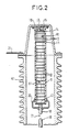
- Figure 2 is a partial view in axial section of the column K1 containing in particular the varistor V1 and the resistor R1.
- the varistor V1 consists of a stack of discs 10 based on zinc oxides or on silicon carbide (CSi); the top and the base of the stack are closed by metal disks, 11 and 12 respectively.
- the resistor R1 consists of a stack of discs 13, for example made of conductive ceramic based on carbon.
- the stack is placed directly above the metal disc 11, and is in contact at its upper part with a metal disc 14.
- a spring 15 presses the disc 14 against the stack R1 by pressing on the inside of a cover metal 16 closing the column K1.
- a metal braid 17 ensures the passage of current between the cover 16 and the disc 14.
- the reference 18 designates the fixed contact of the switch II and the reference 19 the end of the movable contact; as the embodiment of the switch is well known and goes beyond the scope of the present invention, the switch has not been shown in detail.
- the cover 16 is electrically connected by a link 21 to the top of the main breaking chamber 1, not shown in FIG. 2, but shown diagrammatically in FIG. 1.
- column K1 The interior of column K1 is filled with a gas with good dielectric properties promoting cleavage, such as pure or mixed sulfur hexafluoride, under a pressure of a few bars.
- a gas with good dielectric properties promoting cleavage such as pure or mixed sulfur hexafluoride
- FIG. 3 partially represents columns 1 and K1, the resistor R1 being arranged this time outside these columns.
- the varistor V1 always consists of a stack of discs 10, surmounted by a metal disc 25 pressed by a spring 28 bearing on a metal cover 27 closing the column K1.
- a metal braid 28 between the disc 25 and the cover 27 ensures the passage of current.
- Resistor R1 is formed by a stack of discs 13 placed in an insulating tube 30, for example made of epoxy glass, which can be provided with fins 31, for example made of silicone.
- the tube 30 is hermetically closed at its ends by metal plates 32 and 33; the discs 13 are pressed by a spring 34 bearing between the plate 32 and a metal disc 35 at the end of the stack; a metal braid 36, between the plate 32 and the disc 35, ensures the passage of current.
- the tube 30 is arranged horizontally, between the columns 1 and K1, to which it is mechanically and electrically connected.
- connections 37 and 38 respectively connect on the one hand the plate 32 and the metal top 39 of the column 1, and on the other hand the plate 33 and the cover 27.
- Resistor R1 only sees current flow for a very short time. In the "open" or “closed” position of the circuit breaker, the connections 37 and 38 are at the same potential; there is therefore no permanent voltage on the resistor R1.
- the discs 13 can be formed in a single block and closed by molding in a synthetic envelope.
- FIG. 4 illustrates an alternative embodiment, in which the varistor V1 and the resistor R1 are housed in the casing 1 containing the main breaking chamber.
- the varistor V1 is formed by a stack of discs 10 placed in a tube 40 fixed to the cover 41 of the column 1. This cover is placed at the top of a cylindrical insulating envelope 42 provided with fins 43; this envelope, which surmounts column 1, can be made of porcelain or of insulating synthetic material.
- the stacking of the discs 10 is surmounted by a metal disc 44 serving to support a spring 45 which also bears against the cover 41.
- the lower part of the tube 40 serves as a support for the semi-fixed contact for inserting the varistor, as has been described for example in French patent 81 16 291.
- the resistor R1 is formed by one or more rods 70 of small diameter based on carbon (ceramic resistor), housed in insulating tubes 71 and fixed between the cover 41 and the socket 51 of the chamber 1. The number of sticks depends on the energy to be absorbed.
- Reference 52 designates the fixed contact tube for the passage of permanent current.
- FIG. 5 illustrates another embodiment of the invention, for a circuit breaker with two interrupting chambers per phase.
- the elements common to FIG. 5 and to FIG. 1 have been given the same reference numbers or signs.
- Varistors V1 and V2 are arranged in columns K1 and K2 respectively; they are maintained by insulating supports, 81 and 82, fixed to the metal covers 91 and 92 surmounting the columns K1 and K2.
- the metal covers 91 and 92 have horizontal cylindrical extensions 91A and 92A in which the resistors R1 and R2 are housed respectively.
- the resistors R1 and R2 are fixed, on the one hand to the supports 81 and 82, on the other hand to metallic bottoms 91B, 92B closing the cylinders 91A, 92A.
- the bottoms 91B, 92B have current sockets 91C, 92C, connected by a connection tube 94 for placing the two interrupting chambers 1 and 2 in series.
- the columns K1 and K2 and the cylindrical extensions of the covers form sealed assemblies filled with dielectric gas.
- the varistor-resistance pairs, V1, R1 and V2, R2, are found in the same dielectric fluid.
- cover 91 with its horizontal cylindrical extension 91A can very well also be mounted on the insulating casing 1 of the main chamber.
- the invention applies to high voltage circuit breakers and in particular to reactance circuit breakers.
Abstract
Description
La présente invention concerne un disjoncteur à haute tension à varistances.The present invention relates to a high voltage circuit breaker with varistors.
On connaît des disjoncteurs à haute tension équipés de varistances, notamment pour manoeuvrer les réactances shunt des réseaux électriques; le but de la présence des varistances, appelées aussi résistances non linéaires ou variables ou résistances dépendant de la tension, est de réduire les surtensions.High voltage circuit breakers are known which are equipped with varistors, in particular for operating the shunt reactors of the electrical networks; the purpose of the presence of varistors, also called non-linear or variable resistors or resistors depending on the voltage, is to reduce overvoltages.
On sait que plus le seuil de fonctionnement de la varistance est faible, plus la protection contre la surtension est efficace. Plus la surtension est élevée, plus l'énergie absorbée par la varistance est grande.It is known that the lower the operating threshold of the varistor, the more effective the overvoltage protection. The higher the overvoltage, the greater the energy absorbed by the varistor.
La limite de surtension souhaitée est souvent de l'ordre de 1,5 à 1,6 p.u.The desired overvoltage limit is often in the range of 1.5 to 1.6 p.u.
Pour les disjoncteurs de ligne équipés de varistances, il y a un problème important à considérer: d'une part, on souhaite fixer le seuil de surtension à 1,5 p.u.; d'autrepart, la surtension en opposition de phases peut atteindre 2 à 2,5 p.u.For line circuit breakers fitted with varistors, there is an important problem to consider: on the one hand, we want to set the overvoltage threshold at 1.5 p.u .; on the other hand, the overvoltage in phase opposition can reach 2 to 2.5 p.u.
On a proposé de placer, en série avec la varistance, un interrupteur d'ouverture pour éviter une application d'une tension trop élevée sur la varistance; malgré cette disposition, la varistance reste le siège d'une dissipation d'énergie trop importante. Prenons en effet l'exemple d'une opposition de phases, à la coupure; une tension de 2 p.u. environ est appliquée aux varistances pendant 1 période (à 50 ou 60 Hz) avant que l'arc s'éteigne définitivement sur les contacts de l'interrupteur.It has been proposed to place, in series with the varistor, an opening switch to avoid applying too high a voltage to the varistor; despite this arrangement, the varistor remains the seat of too much energy dissipation. Let us take the example of an opposition of phases, at the break; a tension of 2 p.u. approximately is applied to the varistors for 1 period (at 50 or 60 Hz) before the arc goes out definitively on the switch contacts.
On sait qu'à une tension de 2 p.u., le courant peut atteindre une valeur élevée. A titre d'exemple:We know that at a voltage of 2 p.u., the current can reach a high value. For exemple:
à 1 p.u., le courant peut être 5/ IO OOO ampère,at 1 p.u., the current can be 5 / IO OOO ampere,
à 1,5 p.u., le courant atteint 1 ampère,at 1.5 p.u., the current reaches 1 amp,
à 2 p.u., le courant peut dépasser 2 000 ampères.at 2 p.u., the current can exceed 2,000 amps.
Comme la durée d'application de la tension entre 1,5 p.u. et 2 p.u. dure plusieurs millisecondes, l'énergie dissipée dans les varistances atteint plusieurs milliers de kilojoules.As the duration of application of the voltage between 1.5 pu and 2 pu lasts several milliseconds, the energy dissipated in the varistors reaches several thousand kilojoules.
Il est nécessaire de réduire cette énergie, tout en assurant un bon fonctionnement a 1,5 pu.It is necessary to reduce this energy, while ensuring proper operation at 1.5 pu.
Le cas de report de tension aux bornes d'un disjoncteur à chambres multiples, par amorçages partiels, en cas de coupure de défaut ou de ligne a vide, peut aussi entraîner la surcharge thermique des varistances.The case of voltage transfer across a multi-chamber circuit breaker, by partial strikes, in the event of a fault cut or no-load line, can also lead to thermal overload of the varistors.
Un but de la présente invention est de réaliser un disjoncteur à haute tension à varistances permettant la solution de ce problème.An object of the present invention is to provide a high voltage circuit breaker with varistors allowing the solution of this problem.
L'invention a pour objet un disjoncteur à haute tension comprenant au moins une chambre de coupure et, en parallèle sur cette chambre de coupure, d'une part une varistance en série avec un interrupteur et, d'autre part un condensateur de répartition, caractérisé en ce qu'une résistance purement ohmique, de valeur comprise entre 30 et 300 ohms, est insérée en série avec ladite varistance.The subject of the invention is a high voltage circuit breaker comprising at least one breaking chamber and, in parallel on this breaking chamber, on the one hand a varistor in series with a switch and, on the other hand, a distribution capacitor, characterized in that a purely ohmic resistance, of value between 30 and 300 ohms, is inserted in series with said varistor.
Dans un mode particulier de réalisation, la résistance est formée d'un premier empilement de disques disposé dans un tube isolant dans lequel est placé la varistance sous la forme d'un second empilement de disques, ledit tube étant placé a l'intérieur d'une colonne isolante remplie d'un gaz a bonnes propriétés diélectriques.In a particular embodiment, the resistor is formed by a first stack of discs disposed in an insulating tube in which the varistor is placed in the form of a second stack of discs, said tube being placed inside an insulating column filled with a gas having good dielectric properties.
En variante, ladite résistance est formée d'un empilement de disques placés dans un tube isolant, ledit tube étant disposé horizontalement et étant relié mécaniquement et électriquement , d'un côté a une colonne contenant la chambre de coupure principale et, d'un autre côté, à une colonne contenant la varistance.As a variant, said resistor is formed by a stack of discs placed in an insulating tube, said tube being arranged horizontally and being connected mechanically and electrically, on one side to a column containing the main breaking chamber and, on the other side, to a column containing the varistor.
Selon une autre variante, la résistance formée de bâtonnets et la varistance sont logées côte à côte dans l'enveloppe isolante qui surmonte la chambre de coupure principale.According to another variant, the resistance formed by rods and the varistor are housed side by side in the insulating envelope which overcomes the main breaking chamber.
Selon une autre variante, la varistance est disposée dans une colonne munie d'un couvercle ayant un prolongement horizontal contenant la résistance associée, le prolongement étant fermé par un fond muni de prise de courant.According to another variant, the varistor is arranged in a column provided with a cover having a horizontal extension containing the associated resistance, the extension being closed by a bottom provided with current outlet.
Avantageusement, le couvercle ayant un prolongement contenant la résistance surmonte la chambre principale. Le matériau de la varistance est choisi parmi les composés à base d'oxydes de zinc et le carbure de silicium.Advantageously, the cover having an extension containing the resistance overcomes the main chamber. The varistor material is chosen from compounds based on zinc oxides and silicon carbide.
L'invention sera bien comprise à la lecture de la description donnée ci-après de divers modes de mise en oeuvre de l'invention, en référence au dessin annexé dans lequel:
- la figure 1 est une vue schématique d'un disjoncteur selon l'invention, à deux chambres de coupure,
- la figure 2 est une vue partielle en coupe axiale d'une colonne isolante contenant une varistance et sa résistance associée,
- la figure 3 est une vue partielle en coupe axiale d'une colonne isolante contenant une varistance, la résistance associée étant placée entre cette colonne et la colonne contenant la chambre de coupure principale,
- la figure 4 est une vue partielle schématique en coupe d'une autre variante de réalisation dans laquelle la varistance et la résistance sont disposées côte à côtedans la même colonne isolante,
- la figure 5 est une vue schématique d'un disjoncteur à deux chambres de coupure en série, dans lequel la résistance associée à une varistance est disposée dans un prolongement du couvercle de la colonne contenant ladite varistance.
- FIG. 1 is a schematic view of a circuit breaker according to the invention, with two breaking chambers,
- FIG. 2 is a partial view in axial section of an insulating column containing a varistor and its associated resistance,
- FIG. 3 is a partial view in axial section of an insulating column containing a varistor, the associated resistance being placed between this column and the column containing the main breaking chamber,
- FIG. 4 is a schematic partial sectional view of another alternative embodiment in which the varistor and the resistance are arranged side by side in the same insulating column,
- Figure 5 is a schematic view of a circuit breaker with two interrupting chambers in series, wherein the resistor associated with a varistor is arranged in an extension of the cover of the column containing said varistor.
Dans la figure 1, la référence L désigne une phase d'une ligne à haute tension dans laquelle est inséré un disjoncteur comprenant, pour chaque phase, deux chambres de coupure en série 1 et 2. Pour la simplicité du dessin, on n'a pas représenté les supports des chambres de coupure, ni leur mécanismes de manoeuvre. Les chambres de coupure sont, de manière bien connue, constituées d'une colonne isolante remplie d'un gaz à rigidité diélectrique élevée tel que l'hexafluorure de soufre, sous une pression de quelques bars.In FIG. 1, the reference L designates a phase of a high-voltage line into which a circuit breaker is inserted comprising, for each phase, two interrupting chambers in
En parallèle sur chacune des chambres de coupure sont disposés des colonnes isolantes respectivement C1 et C2; ces colonnes renfermant un gaz ou un liquide diélectrique et abritent un condensateur et destiné à la répartition de la tension entre les deux chambres de coupure.In parallel on each of the switching chambers are arranged insulating columns C1 and C2 respectively; these columns contain a gas or a dielectric liquid and house a capacitor and intended for the distribution of the voltage between the two breaking chambers.
Chaque chambre comporte en parallèle une autre colonne, respectivement K1 et K2, à l'intérieur desquels on trouve, reliés en série, une varistance (V1 ,V2) et un interrupteur (I1, I2).Each chamber comprises in parallel another column, respectively K1 and K2, inside which there are, connected in series, a varistor (V1, V2) and a switch (I1, I2).
Selon la principale caractéristique de l'invention, on trouve, en série dans le circuit des colonnes K1 et K2, une résistance (RI, R2).According to the main characteristic of the invention, there is, in series in the circuit of columns K1 and K2, a resistance (RI, R2).
On va montrer sur un exemple comment on peut calculer la valeur des résistances additionnelles R1 et R2. On désignera dans la suite par Ra la valeur ohmique commune des résistances R1 et R2.We will show on an example how we can calculate the value of additional resistors R1 and R2. The common ohmic value of the resistors R1 and R2 will be designated below by Ra.
On souhaite que pour une surtension U égale à 2 p.u., le courant dans la varistance ne dépasse pas une valeur de seuil Is.It is desired that for an overvoltage U equal to 2 p.u., the current in the varistor does not exceed a threshold value Is.
A Is correspond une tension de seuil Us de la varistance. La résistance interne de la varistance à ce seuil est :A Is corresponds a threshold voltage Us of the varistor. The internal resistance of the varistor to this threshold is:
Rs = Us / IsRs = Us / Is
Si Ra est la valeur de la résistance additionnelle permettant de limiter le courant à Is, il vient l'équation de fonctionnement suivante, en négligeant l'impédance du circuit :
- U =
- Is ( Ra + Rs )
- U =
- Is (Ra + Rs)
Prenons un exemple numérique:
- U =
- 900 kV crête
- Is =
- 700 A crête
- Us =
- 845 kV crête
- Rs =
- 1207 ohms
- U =
- 900 kV peak
- Is =
- 700 A peak
- Us =
- 845 kV peak
- Rs =
- 1207 ohms
On en déduit Ra = 80 ohms, soit 40 ohms pour chacune des résistances R1 et R2.We deduce Ra = 80 ohms, or 40 ohms for each of the resistors R1 and R2.
Pendant le passage du courant de 700 Acrête, la tension sur chaque résistance est de 28 000 Vcrête.During the passage of the current of 700 Acrête, the tension on each resistance is 28 000 V peak.
La durée totale de passage à 700 A crête en opposition de phases peut être estimée à 6 millisecondes.The total duration of transition to 700 A peak in phase opposition can be estimated at 6 milliseconds.
Ces considérations permettent de déterminer les dimensions des résistances R1 et R2 qui, d'une manière générale, seront comprises entre 30 et 300 ohmsThese considerations make it possible to determine the dimensions of the resistors R1 and R2 which, in general, will be between 30 and 300 ohms
En revenant à l'exemple précédent, l'énergie thermique dissipée par la résistance lors d'un fonctionnement en opposition de phases sera environ de:

On note qu'en cas de surtension temporaire rapide, (cas de coupure en court-circuit, cas de report de tension), dépassant 2 p.u. ou dépassant le seuil de tension d'un élément de varistance, la présence de la résistance additionnelle Ra permet de réduire efficacement le courant à une valeur acceptable momentanément, par exemple 1 500 ampères en temps court avec 2,4 p.u. La tension aux bornes de chaque résistance R1 et R2 est alors de 60 000 Y crête.It should be noted that in the event of a rapid temporary overvoltage (short-circuit cut-out, voltage transfer case), exceeding 2 p.u. or exceeding the voltage threshold of a varistor element, the presence of the additional resistance Ra makes it possible to effectively reduce the current to an acceptable value momentarily, for example 1,500 amperes in short time with 2.4 p.u. The voltage across each resistor R1 and R2 is then 60,000 Y peak.
En fin de course d'ouverture des interrupteurs I1 et I2, les varistances V1 et V2 sont complètement isolées du circuit.At the end of the opening travel of switches I1 and I2, the varistors V1 and V2 are completely isolated from the circuit.
On note que l'utilisation de résistances additionnelles n'est pas valable pour la protection des défauts phase-terre. En effet, lors d'un coup de foudre frappant la ligne, la présence des résistances additionnelles empêche l'écoulement rapide des charges. Une surtension élevée se produit alors sur la résistance, étant donnée la grande intensité du courant de décharge qui peut atteindre une dizaine de kiloampères, et la grande vitesse d'accroissement du courant.It should be noted that the use of additional resistors is not valid for the protection of phase-to-earth faults. Indeed, during a lightning strike on the line, the presence of additional resistors prevents the rapid flow of charges. A high overvoltage then occurs on the resistor, given the large intensity of the discharge current which can reach ten kiloamperes, and the high speed of current increase.
Il est à noter que pour éviter une chute de tension importante au moment du report de tension qui engendre une fréquence élevée, il faut que la liaison entre la résistance et la varistance soit la plus courte possible.It should be noted that to avoid a significant voltage drop at the time of the voltage transfer which generates a high frequency, the connection between the resistor and the varistor must be as short as possible.
On décrit maintenant plusieurs modes de mise en oeuvre de l'invention.Several embodiments of the invention will now be described.
La figure 2 est une vue partielle en coupe axiale de la colonne K1 contenant notamment la varistance V1 et la résistance R1.Figure 2 is a partial view in axial section of the column K1 containing in particular the varistor V1 and the resistor R1.
A l'intérieur de la colonne céramique K1 est placé un tube en matériau isolant 9 dans lequel sont placées la varistance V1 et la résistance R1. La varistance V1 est constituée d'un empilage de disques 10 à base d'oxydes de zinc ou en carbure de silicium (CSi); le sommet et la base de l'empilage sont fermés par des disques métalliques, respectivement 11 et 12.Inside the ceramic column K1 is placed a tube of insulating material 9 in which the varistor V1 and the resistor R1 are placed. The varistor V1 consists of a stack of
La résistance R1 est constituée d'un empilage de disques 13, par exemple en céramique conductrice à base de carbone. L'empilement est placé directement au dessus du disque métallique 11, et est en contact à sa partie supérieure avec un disque métallique 14. Un ressort 15 presse la disque 14 contre l'empilement R1 en prenant appui sur l'intérieur d'un capot métallique 16 fermant la colonne K1. Une tresse métallique 17 assure le passage du courant entre le capot 16 et le disque 14.The resistor R1 consists of a stack of discs 13, for example made of conductive ceramic based on carbon. The stack is placed directly above the
La référence 18 désigne le contact fixe de l'interrupteur Il et la référence 19 l'extrémité du contact mobile; comme la réalisation de l'interrupteur est bien connue et sort du cadre de la présente invention, l'interrupteur n'a pas été représenté en détail. Un capotage métallique 20, entourant l'extrémité du tube 9 et une partie du contact fixe 18, permet de lisser les courbes équipotentielles dans cette zone.The reference 18 designates the fixed contact of the switch II and the
Le capot 16 est relié électriquement par une liaison 21 au sommet de la chambre de coupure principale 1, non représentée dans la figure 2, mais schématisée dans la figure 1.The
L'intérieur de la colonne K1 est rempli d'un gaz à bonnes propriétés diélectriques favorisant la coupure, tel que l'hexafluorure de soufre, pur ou mélangé, sous une pression de quelques bars.The interior of column K1 is filled with a gas with good dielectric properties promoting cleavage, such as pure or mixed sulfur hexafluoride, under a pressure of a few bars.
La figure 3 représente partiellement les colonnes 1 et K1, la résistance R1 étant disposée cette fois à l'extérieur de ces colonnes.FIG. 3 partially represents columns 1 and K1, the resistor R1 being arranged this time outside these columns.
La varistance V1 est toujours constituée d'un empilage de disques 10, surmontés par un disque métallique 25 pressé par un ressort 28 prenant appui sur un couvercle métallique 27 fermant la colonne K1. Une tresse métallique 28 entre le disque 25 et le couvercle 27 assure le passage du courant.The varistor V1 always consists of a stack of
La résistance R1 est formée d'un empilement de disques 13 placé dans un tube isolant 30, par exemple en verre époxy, pouvant être muni d'ailettes 31, par exemple en silicone.Resistor R1 is formed by a stack of discs 13 placed in an insulating tube 30, for example made of epoxy glass, which can be provided with fins 31, for example made of silicone.
Le tube 30 est fermé hermétiquement à ses extrémités par des plateaux métalliques 32 et 33; les disques 13 sont pressés par un ressort 34 prenant appui entre le plateau 32 et un disque métallique 35 à l'extrémité de l'empilage; une tresse métallique 36, entre le plateau 32 et le disque 35, assure le passage du courant.The tube 30 is hermetically closed at its ends by
Le tube 30 est disposé horizontalement, entre les colonnes 1 et K1, auxquelles il est relié mécaniquement et électriquement. Pour cela, des connexions 37 et 38 relient respectivement d'une part le plateau 32 et le sommet métallique 39 de la colonne 1, et d'autre part le plateau 33 et le couvercle 27.The tube 30 is arranged horizontally, between the columns 1 and K1, to which it is mechanically and electrically connected. For this,
La résistance R1 ne voit le passage du courant que pendant un temps très court. En position "ouvert" ou "fermé" du disjoncteur, les connexions 37 et 38 sont au même potentiel; il n'y a donc pas de tension permanente sur la résistance R1.Resistor R1 only sees current flow for a very short time. In the "open" or "closed" position of the circuit breaker, the
Dans ces conditions,l'utilisation de produits isolants synthétiques ne présente aucun inconvénient.Under these conditions, the use of synthetic insulation products has no drawbacks.
Les disques 13 peuvent être formés d'un seul bloc et fermés sous moulage dans une enveloppe synthétique.The discs 13 can be formed in a single block and closed by molding in a synthetic envelope.
La figure 4 illustre une variante de réalisation, dans laquelle la varistance V1 et la résistance R1 sont logées dans l'enveloppe 1 contenant la chambre de coupure principale.FIG. 4 illustrates an alternative embodiment, in which the varistor V1 and the resistor R1 are housed in the casing 1 containing the main breaking chamber.
La varistance V1 est formée d'un empilage de disques 10 placés dans un tube 40 fixé au couvercle 41 de la colonne 1. Ce couvercle est placé au sommet d'une enveloppe cylindrique isolante 42 munie d'ailettes 43; cette enveloppe, qui surmonte la colonne 1, peut être en porcelaine ou en matière synthétique isolante.The varistor V1 is formed by a stack of
Comme précédemment, l'empilage des disques 10 est surmonté d'un disque métallique 44 servant d'appui à un ressort 45 s'appuyant par ailleurs contre le couvercle 41.As before, the stacking of the
La partie inférieure du tube 40, non représentée, sert de support au contact semi-fixe d'insertion de la varistance, comme il a été décrit par exemple dans le brevet français 81 16 291.The lower part of the
La résistance R1 est formée d'un ou plusieurs bâtonnets 70 de faible diamètre à base de carbone (résistance céramique), logés dans des tubes isolants 71 et fixés entre le couvercle 41 et la prise de courant 51 de la chambre 1. Le nombre de bâtonnets dépend de l'énergie à absorber.The resistor R1 is formed by one or
La référence 52 désigne le tube de contact fixe pour le passage du courant permanent.
La figure 5 illustre un autre mode de réalisation de l'invention, pour un disjoncteur à deux chambres de coupure par phase. Les éléments communs à la figure 5 et à la figure 1 ont reçu les mêmes numéros ou signes de référence.FIG. 5 illustrates another embodiment of the invention, for a circuit breaker with two interrupting chambers per phase. The elements common to FIG. 5 and to FIG. 1 have been given the same reference numbers or signs.
Les varistances V1 et V2 sont disposées dans les colonnes K1 et K2 respectivement; elles sont maintenues par des supports isolants, 81 et 82, fixés aux couvercles métalliques 91 et 92 surmontant les colonnes K1 et K2.Varistors V1 and V2 are arranged in columns K1 and K2 respectively; they are maintained by insulating supports, 81 and 82, fixed to the metal covers 91 and 92 surmounting the columns K1 and K2.
Les couvercles métalliques 91 et 92 possèdent des prolongements cylindriques horizontaux 91A et 92A dans lesquels sont logées respectivement les résistances R1 et R2. Les résistances R1 et R2 sont fixées, d"une part aux supports 81 et 82, d'autre part à des fonds métalliques 91B, 92B fermant les cylindres 91A, 92A. Les fonds 91B, 92B possèdent des prises de courant 91C, 92C, reliées par un tube de connexion 94 pour la mise en série des deux chambres de coupure 1 et 2.The metal covers 91 and 92 have horizontal
Les colonnes K1 et K2 et les prolongements cylindriques des couvercles forment des ensembles étanches remplis de gaz diélectrique. Les couples varistance-résistances, V1, R1 et V2, R2, se trouvent dans le même fluide diélectrique.The columns K1 and K2 and the cylindrical extensions of the covers form sealed assemblies filled with dielectric gas. The varistor-resistance pairs, V1, R1 and V2, R2, are found in the same dielectric fluid.
Bien entendu, le couvercle 91 avec son prolongement cylindrique horizontal 91A peut très bien être monté aussi sur l'enveloppe isolante 1 de la chambre principale.Of course, the
L'invention n'est pas limitée aux modes de réalisation décrits et représentés. On peut, sans sortir du cadre de l'invention, remplacer certains moyens par des moyens équivalents.The invention is not limited to the embodiments described and shown. Without departing from the scope of the invention, it is possible to replace certain means with equivalent means.
L'invention s'applique aux disjoncteurs à haute tension et en particulier aux disjoncteurs de réactance.The invention applies to high voltage circuit breakers and in particular to reactance circuit breakers.
Claims (7)
Applications Claiming Priority (2)
| Application Number | Priority Date | Filing Date | Title |
|---|---|---|---|
| FR8915713 | 1989-11-29 | ||
| FR8915713A FR2655188B1 (en) | 1989-11-29 | 1989-11-29 | HIGH VOLTAGE CIRCUIT BREAKER AT VARISTANCES. |
Publications (2)
| Publication Number | Publication Date |
|---|---|
| EP0430123A1 true EP0430123A1 (en) | 1991-06-05 |
| EP0430123B1 EP0430123B1 (en) | 1994-10-12 |
Family
ID=9387918
Family Applications (1)
| Application Number | Title | Priority Date | Filing Date |
|---|---|---|---|
| EP90122515A Expired - Lifetime EP0430123B1 (en) | 1989-11-29 | 1990-11-26 | High-tension switch with variators |
Country Status (10)
| Country | Link |
|---|---|
| US (1) | US5124872A (en) |
| EP (1) | EP0430123B1 (en) |
| JP (1) | JPH06101277B2 (en) |
| CN (1) | CN1024969C (en) |
| AT (1) | ATE112887T1 (en) |
| BR (1) | BR9006024A (en) |
| CA (1) | CA2030980C (en) |
| DE (1) | DE69013295T2 (en) |
| ES (1) | ES2064589T3 (en) |
| FR (1) | FR2655188B1 (en) |
Cited By (3)
| Publication number | Priority date | Publication date | Assignee | Title |
|---|---|---|---|---|
| FR2680043A1 (en) * | 1991-08-02 | 1993-02-05 | Alsthom Gec | Circuit breaker with multiple cutoff equipped with varistors |
| EP0536039A1 (en) * | 1991-10-02 | 1993-04-07 | Gec Alsthom Sa | Ultra-high voltage circuit breaker |
| FR2688623A1 (en) * | 1992-03-13 | 1993-09-17 | Asea Brown Boveri | Reactor switch |
Families Citing this family (15)
| Publication number | Priority date | Publication date | Assignee | Title |
|---|---|---|---|---|
| FR2668648B1 (en) * | 1990-10-24 | 1992-12-24 | Alsthom Gec | SF6 CIRCUIT BREAKER WITH INCORPORATED CAPACITOR. |
| FR2674984B1 (en) * | 1991-04-05 | 1993-06-11 | Alsthom Gec | SF6 CIRCUIT BREAKER WITH INCORPORATED CAPACITOR. |
| JPH0576136A (en) * | 1991-09-13 | 1993-03-26 | Hitachi Ltd | Power supply system |
| SE510178C2 (en) * | 1991-09-16 | 1999-04-26 | Asea Brown Boveri | Ventilavledaranordning |
| EP0555144A1 (en) * | 1992-02-07 | 1993-08-11 | Gec Alsthom Sa | Pump station |
| US6236010B1 (en) | 1999-07-14 | 2001-05-22 | Southern States, Inc. | Circuit interrupter including a penetrating electrical contact with grip and release structure |
| US6316742B1 (en) | 1999-07-14 | 2001-11-13 | Southern States, Inc. | Limited restrike circuit interrupter used as a line capacitor and load switch |
| CN101217078B (en) * | 2008-01-04 | 2011-06-01 | 西安交通大学 | A permanent magnetic actuator vacuum circuit breaker assembly with series resistance |
| US8692537B2 (en) * | 2009-07-17 | 2014-04-08 | The Invention Science Fund I, Llc | Use pairs of transformers to increase transmission line voltage |
| US8426736B2 (en) * | 2009-07-17 | 2013-04-23 | The Invention Science Fund I Llc | Maintaining insulators in power transmission systems |
| US20110011621A1 (en) * | 2009-07-17 | 2011-01-20 | Searete Llc, A Limited Liability Corporation Of The State Of Delaware | Smart link coupled to power line |
| JP2013197010A (en) * | 2012-03-22 | 2013-09-30 | Toshiba Corp | Gas circuit breaker |
| CN103578843A (en) * | 2013-11-08 | 2014-02-12 | 西安盟创电器有限公司 | Non-reignition disconnector |
| CN111696817A (en) * | 2020-03-25 | 2020-09-22 | 天津平高智能电气有限公司 | High-voltage switch and shell thereof |
| CN112382527B (en) * | 2020-12-01 | 2023-12-19 | 郑州大学 | Self-equalizing control method for dynamic charge compensation of multi-fracture vacuum circuit breaker |
Citations (5)
| Publication number | Priority date | Publication date | Assignee | Title |
|---|---|---|---|---|
| GB565410A (en) * | 1943-05-01 | 1944-11-09 | William Alexander Mcneill | Improvements in and relating to air or gas blast electric circuit breakers |
| FR1424922A (en) * | 1964-02-18 | 1966-01-14 | English Electric Co Ltd | Electrical switchgear |
| GB1112745A (en) * | 1965-12-03 | 1968-05-08 | Ass Elect Ind | Improvements in and relating to circuit breakers |
| FR2512267A1 (en) * | 1981-08-26 | 1983-03-04 | Alsthom Atlantique | COMPRESSED GAS CIRCUIT BREAKER WITH OPENING AND CLOSING RESISTORS |
| EP0117914A2 (en) * | 1982-12-09 | 1984-09-12 | Hitachi, Ltd. | Circuit breaker having a parallel resistor arrangement |
Family Cites Families (3)
| Publication number | Priority date | Publication date | Assignee | Title |
|---|---|---|---|---|
| JPS553136A (en) * | 1978-06-23 | 1980-01-10 | Hitachi Ltd | Breaker |
| JPS5557219A (en) * | 1978-10-25 | 1980-04-26 | Hitachi Ltd | Power breaker |
| JPS58186118A (en) * | 1982-04-23 | 1983-10-31 | 株式会社日立製作所 | Voltage dividing device for dc breaker |
-
1989
- 1989-11-29 FR FR8915713A patent/FR2655188B1/en not_active Expired - Lifetime
-
1990
- 1990-11-21 US US07/618,206 patent/US5124872A/en not_active Expired - Fee Related
- 1990-11-26 DE DE69013295T patent/DE69013295T2/en not_active Expired - Fee Related
- 1990-11-26 EP EP90122515A patent/EP0430123B1/en not_active Expired - Lifetime
- 1990-11-26 AT AT90122515T patent/ATE112887T1/en not_active IP Right Cessation
- 1990-11-26 ES ES90122515T patent/ES2064589T3/en not_active Expired - Lifetime
- 1990-11-28 BR BR909006024A patent/BR9006024A/en not_active Application Discontinuation
- 1990-11-28 CA CA002030980A patent/CA2030980C/en not_active Expired - Fee Related
- 1990-11-29 CN CN90109553.2A patent/CN1024969C/en not_active Expired - Fee Related
- 1990-11-29 JP JP2333507A patent/JPH06101277B2/en not_active Expired - Lifetime
Patent Citations (5)
| Publication number | Priority date | Publication date | Assignee | Title |
|---|---|---|---|---|
| GB565410A (en) * | 1943-05-01 | 1944-11-09 | William Alexander Mcneill | Improvements in and relating to air or gas blast electric circuit breakers |
| FR1424922A (en) * | 1964-02-18 | 1966-01-14 | English Electric Co Ltd | Electrical switchgear |
| GB1112745A (en) * | 1965-12-03 | 1968-05-08 | Ass Elect Ind | Improvements in and relating to circuit breakers |
| FR2512267A1 (en) * | 1981-08-26 | 1983-03-04 | Alsthom Atlantique | COMPRESSED GAS CIRCUIT BREAKER WITH OPENING AND CLOSING RESISTORS |
| EP0117914A2 (en) * | 1982-12-09 | 1984-09-12 | Hitachi, Ltd. | Circuit breaker having a parallel resistor arrangement |
Cited By (5)
| Publication number | Priority date | Publication date | Assignee | Title |
|---|---|---|---|---|
| FR2680043A1 (en) * | 1991-08-02 | 1993-02-05 | Alsthom Gec | Circuit breaker with multiple cutoff equipped with varistors |
| EP0536039A1 (en) * | 1991-10-02 | 1993-04-07 | Gec Alsthom Sa | Ultra-high voltage circuit breaker |
| FR2682219A1 (en) * | 1991-10-02 | 1993-04-09 | Alsthom Gec | ULTRA HIGH VOLTAGE CIRCUIT BREAKER. |
| US5304760A (en) * | 1991-10-02 | 1994-04-19 | Gec Alsthom Sa | Ultra-high-tension circuit-breaker |
| FR2688623A1 (en) * | 1992-03-13 | 1993-09-17 | Asea Brown Boveri | Reactor switch |
Also Published As
| Publication number | Publication date |
|---|---|
| CN1024969C (en) | 1994-06-08 |
| ES2064589T3 (en) | 1995-02-01 |
| CA2030980A1 (en) | 1991-05-30 |
| DE69013295T2 (en) | 1995-02-16 |
| BR9006024A (en) | 1991-09-24 |
| JPH06101277B2 (en) | 1994-12-12 |
| JPH03182023A (en) | 1991-08-08 |
| CN1063965A (en) | 1992-08-26 |
| CA2030980C (en) | 1994-07-05 |
| EP0430123B1 (en) | 1994-10-12 |
| ATE112887T1 (en) | 1994-10-15 |
| FR2655188B1 (en) | 1992-02-07 |
| US5124872A (en) | 1992-06-23 |
| FR2655188A1 (en) | 1991-05-31 |
| DE69013295D1 (en) | 1994-11-17 |
Similar Documents
| Publication | Publication Date | Title |
|---|---|---|
| EP0430123B1 (en) | High-tension switch with variators | |
| CA2037119C (en) | Varistor assisted circuit breaker | |
| CA2028592C (en) | Voltage limiting circuit-breaker | |
| EP0482555B1 (en) | SF6 circuit breaker with built-in condensor | |
| CA2044517C (en) | Integral varistor airconnect switch | |
| CH636473A5 (en) | MICROPARAFOUDRE WITH HIGH FLOW CAPACITY. | |
| CA2068857C (en) | Circuit breaker with high breaking capacity | |
| FR2476381A1 (en) | ISOLATED GAS DISCONNECT | |
| EP0536039B1 (en) | Ultra-high voltage circuit breaker | |
| EP1953788B1 (en) | Device for protecting against voltage surges with a mobile electrode with system for unlocking the disconnection device | |
| EP1842269A2 (en) | Electrical installation protection device with improved interrupting capacity | |
| EP0415098B1 (en) | Self-blast circuit breaker for medium voltage | |
| EP0027061B1 (en) | Lightning arrester device allowing an external short-circuiting and corresponding protection assembly | |
| EP0782753B1 (en) | Lightning arrester device | |
| EP1829176B1 (en) | Improved-disconnection overvoltage protection device and corresponding method | |
| FR2658949A1 (en) | Circuit breaker with cutoff assisted by varistor | |
| FR2733353A1 (en) | Fault current limiter for HV network | |
| FR2688624A1 (en) | INERTIA CONTACT FOR CIRCUIT BREAKER ALLOWING THE TEMPORARY INSERTION OF AN IMPEDANCE. | |
| FR2484695A1 (en) | Gas filled lightning arrester with external short-circuit - imposed by spring conductor making contact with electrode after melting of spacer | |
| FR2481011A1 (en) | Overvoltage protection fuse for electronic circuit - uses telescopic movement of two tubes held spaced by melting fuse to obtain short-circuit | |
| FR2709019A1 (en) | Circuit breaker with insertion of opening resistance by multiple arcs | |
| EP0627751A1 (en) | Circuit breaker with double arc lengthening for switching currents with a high DC component | |
| FR2658660A1 (en) | Low-overvoltage circuit breaker with varistor |
Legal Events
| Date | Code | Title | Description |
|---|---|---|---|
| PUAI | Public reference made under article 153(3) epc to a published international application that has entered the european phase |
Free format text: ORIGINAL CODE: 0009012 |
|
| AK | Designated contracting states |
Kind code of ref document: A1 Designated state(s): AT BE CH DE DK ES FR GB GR IT LI LU NL SE |
|
| 17P | Request for examination filed |
Effective date: 19911202 |
|
| 17Q | First examination report despatched |
Effective date: 19931221 |
|
| GRAA | (expected) grant |
Free format text: ORIGINAL CODE: 0009210 |
|
| AK | Designated contracting states |
Kind code of ref document: B1 Designated state(s): AT BE CH DE DK ES FR GB GR IT LI LU NL SE |
|
| PG25 | Lapsed in a contracting state [announced via postgrant information from national office to epo] |
Ref country code: NL Effective date: 19941012 Ref country code: GR Free format text: LAPSE BECAUSE OF FAILURE TO SUBMIT A TRANSLATION OF THE DESCRIPTION OR TO PAY THE FEE WITHIN THE PRESCRIBED TIME-LIMIT Effective date: 19941012 Ref country code: DK Effective date: 19941012 |
|
| REF | Corresponds to: |
Ref document number: 112887 Country of ref document: AT Date of ref document: 19941015 Kind code of ref document: T |
|
| REF | Corresponds to: |
Ref document number: 69013295 Country of ref document: DE Date of ref document: 19941117 |
|
| PG25 | Lapsed in a contracting state [announced via postgrant information from national office to epo] |
Ref country code: LU Free format text: LAPSE BECAUSE OF NON-PAYMENT OF DUE FEES Effective date: 19941130 Ref country code: BE Effective date: 19941130 |
|
| GBT | Gb: translation of ep patent filed (gb section 77(6)(a)/1977) |
Effective date: 19941103 |
|
| ITF | It: translation for a ep patent filed |
Owner name: JACOBACCI CASETTA & PERANI S.P.A. |
|
| EAL | Se: european patent in force in sweden |
Ref document number: 90122515.1 |
|
| REG | Reference to a national code |
Ref country code: ES Ref legal event code: FG2A Ref document number: 2064589 Country of ref document: ES Kind code of ref document: T3 |
|
| NLV1 | Nl: lapsed or annulled due to failure to fulfill the requirements of art. 29p and 29m of the patents act | ||
| BERE | Be: lapsed |
Owner name: S.A. GEC ALSTHOM Effective date: 19941130 |
|
| PLBE | No opposition filed within time limit |
Free format text: ORIGINAL CODE: 0009261 |
|
| STAA | Information on the status of an ep patent application or granted ep patent |
Free format text: STATUS: NO OPPOSITION FILED WITHIN TIME LIMIT |
|
| 26N | No opposition filed | ||
| PGFP | Annual fee paid to national office [announced via postgrant information from national office to epo] |
Ref country code: AT Payment date: 19951130 Year of fee payment: 6 |
|
| PGFP | Annual fee paid to national office [announced via postgrant information from national office to epo] |
Ref country code: SE Payment date: 19960812 Year of fee payment: 7 |
|
| PGFP | Annual fee paid to national office [announced via postgrant information from national office to epo] |
Ref country code: DE Payment date: 19960814 Year of fee payment: 7 |
|
| PGFP | Annual fee paid to national office [announced via postgrant information from national office to epo] |
Ref country code: FR Payment date: 19960912 Year of fee payment: 7 |
|
| PGFP | Annual fee paid to national office [announced via postgrant information from national office to epo] |
Ref country code: GB Payment date: 19961011 Year of fee payment: 7 |
|
| PGFP | Annual fee paid to national office [announced via postgrant information from national office to epo] |
Ref country code: CH Payment date: 19961029 Year of fee payment: 7 |
|
| PGFP | Annual fee paid to national office [announced via postgrant information from national office to epo] |
Ref country code: ES Payment date: 19961112 Year of fee payment: 7 |
|
| PG25 | Lapsed in a contracting state [announced via postgrant information from national office to epo] |
Ref country code: AT Effective date: 19961126 |
|
| PG25 | Lapsed in a contracting state [announced via postgrant information from national office to epo] |
Ref country code: GB Free format text: LAPSE BECAUSE OF NON-PAYMENT OF DUE FEES Effective date: 19971126 |
|
| PG25 | Lapsed in a contracting state [announced via postgrant information from national office to epo] |
Ref country code: SE Free format text: LAPSE BECAUSE OF NON-PAYMENT OF DUE FEES Effective date: 19971127 Ref country code: ES Free format text: LAPSE BECAUSE OF THE APPLICANT RENOUNCES Effective date: 19971127 |
|
| PG25 | Lapsed in a contracting state [announced via postgrant information from national office to epo] |
Ref country code: LI Free format text: LAPSE BECAUSE OF NON-PAYMENT OF DUE FEES Effective date: 19971130 Ref country code: FR Free format text: THE PATENT HAS BEEN ANNULLED BY A DECISION OF A NATIONAL AUTHORITY Effective date: 19971130 Ref country code: CH Free format text: LAPSE BECAUSE OF NON-PAYMENT OF DUE FEES Effective date: 19971130 |
|
| GBPC | Gb: european patent ceased through non-payment of renewal fee |
Effective date: 19971126 |
|
| REG | Reference to a national code |
Ref country code: CH Ref legal event code: PL |
|
| PG25 | Lapsed in a contracting state [announced via postgrant information from national office to epo] |
Ref country code: DE Free format text: LAPSE BECAUSE OF NON-PAYMENT OF DUE FEES Effective date: 19980801 |
|
| EUG | Se: european patent has lapsed |
Ref document number: 90122515.1 |
|
| REG | Reference to a national code |
Ref country code: FR Ref legal event code: ST |
|
| REG | Reference to a national code |
Ref country code: ES Ref legal event code: FD2A Effective date: 20010402 |
|
| PG25 | Lapsed in a contracting state [announced via postgrant information from national office to epo] |
Ref country code: IT Free format text: LAPSE BECAUSE OF NON-PAYMENT OF DUE FEES;WARNING: LAPSES OF ITALIAN PATENTS WITH EFFECTIVE DATE BEFORE 2007 MAY HAVE OCCURRED AT ANY TIME BEFORE 2007. THE CORRECT EFFECTIVE DATE MAY BE DIFFERENT FROM THE ONE RECORDED. Effective date: 20051126 |