EP0430099B1 - Radialkolbenpumpe, insbesondere für Hydraulikanlagen sowie Druckerzeugungselement hierfür - Google Patents
Radialkolbenpumpe, insbesondere für Hydraulikanlagen sowie Druckerzeugungselement hierfür Download PDFInfo
- Publication number
- EP0430099B1 EP0430099B1 EP90122409A EP90122409A EP0430099B1 EP 0430099 B1 EP0430099 B1 EP 0430099B1 EP 90122409 A EP90122409 A EP 90122409A EP 90122409 A EP90122409 A EP 90122409A EP 0430099 B1 EP0430099 B1 EP 0430099B1
- Authority
- EP
- European Patent Office
- Prior art keywords
- piston
- pressure
- generating element
- suction
- receiving opening
- Prior art date
- Legal status (The legal status is an assumption and is not a legal conclusion. Google has not performed a legal analysis and makes no representation as to the accuracy of the status listed.)
- Expired - Lifetime
Links
- 238000009434 installation Methods 0.000 claims description 2
- 230000037431 insertion Effects 0.000 claims 1
- 238000003780 insertion Methods 0.000 claims 1
- 239000012530 fluid Substances 0.000 description 7
- 230000006835 compression Effects 0.000 description 4
- 238000007906 compression Methods 0.000 description 4
- 230000002706 hydrostatic effect Effects 0.000 description 3
- 238000004519 manufacturing process Methods 0.000 description 2
- 238000010521 absorption reaction Methods 0.000 description 1
- 230000006978 adaptation Effects 0.000 description 1
- 238000010276 construction Methods 0.000 description 1
- 230000007797 corrosion Effects 0.000 description 1
- 238000005260 corrosion Methods 0.000 description 1
- 230000006378 damage Effects 0.000 description 1
- 230000002349 favourable effect Effects 0.000 description 1
- 239000000126 substance Substances 0.000 description 1
Images

Classifications
-
- F—MECHANICAL ENGINEERING; LIGHTING; HEATING; WEAPONS; BLASTING
- F04—POSITIVE - DISPLACEMENT MACHINES FOR LIQUIDS; PUMPS FOR LIQUIDS OR ELASTIC FLUIDS
- F04B—POSITIVE-DISPLACEMENT MACHINES FOR LIQUIDS; PUMPS
- F04B1/00—Multi-cylinder machines or pumps characterised by number or arrangement of cylinders
- F04B1/04—Multi-cylinder machines or pumps characterised by number or arrangement of cylinders having cylinders in star- or fan-arrangement
- F04B1/0404—Details or component parts
- F04B1/0421—Cylinders
-
- F—MECHANICAL ENGINEERING; LIGHTING; HEATING; WEAPONS; BLASTING
- F04—POSITIVE - DISPLACEMENT MACHINES FOR LIQUIDS; PUMPS FOR LIQUIDS OR ELASTIC FLUIDS
- F04B—POSITIVE-DISPLACEMENT MACHINES FOR LIQUIDS; PUMPS
- F04B1/00—Multi-cylinder machines or pumps characterised by number or arrangement of cylinders
- F04B1/04—Multi-cylinder machines or pumps characterised by number or arrangement of cylinders having cylinders in star- or fan-arrangement
- F04B1/0404—Details or component parts
- F04B1/0439—Supporting or guiding means for the pistons
Definitions
- the present invention relates to radial piston pumps, in particular for hydraulic systems.
- radial piston pumps as are known for example from DE-OS 35 00 432, DE-OS 34 24 862, DE-OS 30 39 197 and DE-GM 85 04 213, a plurality of cylindrical pressure generating elements with piston receiving part and sliding therein the piston is screwed radially to a drive shaft with an eccentric in a common pump housing.
- the pressure generating elements or more precisely the piston receiving parts of the pressure generating elements have a cuboid shape and are on carrier elements or on the pump housing screwed on.
- the design of the pressure generating elements as separate components detachable from the radial piston pump as a whole allows flexible adaptation of one and the same pump body to different requirements with regard to the media to be conveyed, the pressures to be generated, etc.
- radial piston pumps such as those described in DE-PS 923 589 or EP-A-0 304 743 are known, however, there is the disadvantage that there is a risk of deforming the piston bore in the piston receiving part by screwing the cuboid piston receiving part onto the pump housing or onto a carrier part. Since radial piston pumps are also operated at speeds of up to 3000 revolutions per minute and more, this can easily lead to the destruction of the pressure generating elements. Prepared for radial piston pumps with external pressure elements screwed into the pump housing the sensible arrangement of the valves is difficult, since it is very difficult to arrange valves or suction and pressure connections across the screwing direction.
- the component supporting the receiving opening can be designed according to different requirements, such as mechanical strength, vibration and sound absorption behavior, corrosion resistance, specific weight, etc.
- the component carrying the receiving opening can simultaneously take over the function of the piston head. Due to the axial arrangement of the pressure generating element in the component carrying the receiving opening, the pressure and suction connections or pressure and pressure valves can be arranged almost anywhere in or on the pressure generating element.
- the receiving opening and / or the pressure generating element or piston receiving part inserted into the receiving opening is point-symmetrical with respect to the axial direction of installation.
- the receiving opening can thus be designed in the form of a bore with a constant cross section. This simplifies the manufacture of the radial piston pump according to the invention.
- the receiving opening and / or the outside of the pressure generating element or the piston receiving part is profiled.
- this profiling can have a favorable influence on the noise emission and, on the other hand, the piston receiving part can be locked in a simple manner tangential to the drive shaft.
- the locking of the pressure generating element or the piston receiving part in the component carrying the receiving opening can additionally or alternatively by a fastening means, e.g. done in the form of a pin.
- the size of the pressure generating element, in particular the piston receiving part can be reduced.
- the piston 16 is moved during the pressure stroke by an eccentric 24 fastened on the drive shaft 2; up in the drawing.
- the piston 16 is hollow and, together with the piston bore 18, forms a compression space 17.
- the piston 16 can be sealed against the piston bore 18 with a seal, not shown, which surrounds the piston 16 in a ring.
- a piston spring 26 which is arranged in the interior of the piston 16 and is supported in the piston 16 itself and in the piston receiving part 14 at the bottom of the piston bore 18.
- the suction channel 20 is integrated in the piston 16, while the pressure connection is provided laterally in the piston receiving part 14 in contact with the pressure plate 4.
- a suction valve 30 or a pressure valve 32 is arranged in the form of ball valves.
- the suction valve 30 consists of a ball 34, which is pressed by a suction valve spring 36 against a suction valve seat 38 inside the piston 16 and seals the suction channel 20 against the piston drive chamber 7 during the pressure stroke.
- the suction valve spring 36 is supported on the bottom of the piston bore 18 on the piston receiving part 14 and on the ball 34.
- the pressure channel 22 connects the compression space 17 to a pressure connection line 40 accommodated in the pressure plate 4.
- the pressure valve 32 is accommodated with a pressure valve spring 42, a ball 44 and a ball stop 46.
- the pressure channel 22 is sealed off from the pressure plate 4 by a seal 48.
- the piston 16 Due to the rotary movement of the drive shaft 2, the piston 16 is periodically pushed into the piston receiving part 14 by the eccentric 24 - pressure stroke - and periodically pushed out of the piston receiving part 14 again by the piston spring 26 to the lower reversal point.
- the ball 34 is lifted off the ball seat against the suction valve spring 36 and the fluid can flow through the T-shaped suction channel 20 into the compression space 17 into the piston bore 18.
- the pressure channel 22 is closed off by the ball 44 loaded by the pressure valve spring 42.
- the piston 16 If, during the pressure stroke, the piston 16 is moved into the upper reversal point by the eccentric 24, the suction valve spring 36 and the higher pressure which builds up pushes the ball 34 onto the suction valve seat 38 and the ball 44 is pressed against the pressure valve spring 42 due to the high pressure building up lifted from their seat.
- the ball stop 46 limits the possible path of the ball 44 in the fluid flowing into the pressure channel 22.
- the suction valve 30 is arranged at the end of the T-shaped suction channel 20 in the interior of the piston 16.
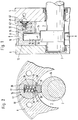
- the suction valve 30 can not only be accommodated in the piston, but almost anywhere in the pressure generating element. Examples of this are shown in the pressure generating elements 60 and 70 according to FIGS. 6 and 7.
- the embodiment of the pressure generating element 60 according to FIG. 6 has a suction channel 62 which is arranged parallel to the piston bore 18.
- the suction channel 62 opens next to the piston bore 18 in the piston drive chamber 17, so that the fluid to be compressed can be sucked out of the piston drive chamber 17.
- a suction valve 66 is arranged immediately behind the mouth of the suction channel 62 in the piston drive chamber 17.
- the suction valve 66 differs from the suction valve 30 only in the configuration of the suction valve spring.
- the suction valve 66 has a suction valve spring 68 which is supported on a shoulder 69 and not on the bottom of the piston bore 18, as is the case with the suction valve spring 36 of the above-described embodiments.
- the suction channel 62 opens into the pressure channel 22 in the the pressure valve 32 is housed.
- the design and function of the pressure valve 32 and the other components completely match the design and function of the embodiments according to FIGS. 1 to 5, so that a detailed description is unnecessary.
- FIG. 7 shows a further embodiment of a pressure generating element 70.
- the pressure generating element 70 has a suction channel 72, which does not open into the piston drive space, but rather into a suction feed line 74 accommodated in the flange plate 6. Suction channel 72 or suction feed line 74 are sealed by a seal 76 .
- the suction valve 78 accommodated in the suction channel 72 completely matches the suction valve 66 of the pressure generating element 60.
- the embodiment according to FIG. 7 is particularly advantageous in the case of fluids to be compressed which, owing to their chemical (for example corrosive), physical (for example temperature) and / or biological (for example bacteriologically contaminated) properties, are to be carried out separately from the other parts of the radial piston pump .
- FIG. 8 shows a design of a piston 80 that is particularly suitable for the delivery of such fluids.
- a piston spring 82 surrounds the piston 80 in the region that protrudes from the piston bore.
- the piston spring 82 is supported on the edge of the piston bore 18 and on a shoulder 84.
- the embodiment of the piston according to FIG. 8 is not limited to the conveyance of corrosive media.
- FIG. 9 shows a special configuration of a piston 90.
- the piston 90 consists of a piston part 91 and a sliding washer 92.
- transverse forces can be reduced which can occur due to manufacturing tolerances.
- this type of hydrostatic relief is only possible if the suction channel is not inside the piston.
- the embodiment of the piston 90 is therefore particularly suitable for the pressure generating element 60 shown in FIG. 6.
- the piston 100 shown in FIG. 10 shows a possibility for a hydrostatic relief.
- a relief bore 104 is placed in the direction of movement of the piston so that it does not pass through a transverse T-shaped suction channel 102.
- the relief bore 104 is shown in FIG. 10 offset by 90 ° for reasons of drawing.
Landscapes
- Engineering & Computer Science (AREA)
- Mechanical Engineering (AREA)
- General Engineering & Computer Science (AREA)
- Details Of Reciprocating Pumps (AREA)
- Reciprocating Pumps (AREA)
Applications Claiming Priority (2)
| Application Number | Priority Date | Filing Date | Title |
|---|---|---|---|
| DE3939184 | 1989-11-27 | ||
| DE3939184A DE3939184A1 (de) | 1989-11-27 | 1989-11-27 | Radialkolbenpumpe, insbesondere fuer hydraulikanlagen sowie druckerzeugungselement hierfuer |
Publications (2)
| Publication Number | Publication Date |
|---|---|
| EP0430099A1 EP0430099A1 (de) | 1991-06-05 |
| EP0430099B1 true EP0430099B1 (de) | 1994-10-05 |
Family
ID=6394279
Family Applications (1)
| Application Number | Title | Priority Date | Filing Date |
|---|---|---|---|
| EP90122409A Expired - Lifetime EP0430099B1 (de) | 1989-11-27 | 1990-11-23 | Radialkolbenpumpe, insbesondere für Hydraulikanlagen sowie Druckerzeugungselement hierfür |
Country Status (2)
| Country | Link |
|---|---|
| EP (1) | EP0430099B1 (cg-RX-API-DMAC7.html) |
| DE (2) | DE3939184A1 (cg-RX-API-DMAC7.html) |
Families Citing this family (2)
| Publication number | Priority date | Publication date | Assignee | Title |
|---|---|---|---|---|
| DE4241827A1 (de) * | 1992-12-11 | 1994-06-16 | Teves Gmbh Alfred | Geräuschreduziertes Pumpenaggregat, insbesondere für geregelte Bremsanlagen |
| EP1056948B1 (de) * | 1998-02-17 | 2004-10-13 | Continental Teves AG & Co. oHG | Kolbenpumpe |
Family Cites Families (6)
| Publication number | Priority date | Publication date | Assignee | Title |
|---|---|---|---|---|
| FR22669E (fr) * | 1919-12-24 | 1921-08-04 | Francois Louis Caut | Dispositif rotatif pouvant servir de pompe, de moteur transmetteur de mouvement, de frein et autres applications |
| GB533405A (en) * | 1939-11-03 | 1941-02-12 | Automotive Prod Co Ltd | Improvements in or relating to reciprocating pumps |
| DE923589C (de) * | 1949-11-18 | 1955-02-17 | Heilmeier & Weinlein O H G | Hydraulik-Kolbenpumpe |
| FR2323031A1 (fr) * | 1975-09-08 | 1977-04-01 | Ferodo Sa | Machine tournante hydraulique |
| DE3330803A1 (de) * | 1983-08-26 | 1985-03-14 | Robert Bosch Gmbh, 7000 Stuttgart | Foerderelement |
| IT212433Z2 (it) * | 1987-08-25 | 1989-07-04 | Weber Srl | Pompa a stantuffi radiali |
-
1989
- 1989-11-27 DE DE3939184A patent/DE3939184A1/de active Granted
-
1990
- 1990-11-23 EP EP90122409A patent/EP0430099B1/de not_active Expired - Lifetime
- 1990-11-23 DE DE59007385T patent/DE59007385D1/de not_active Expired - Fee Related
Also Published As
| Publication number | Publication date |
|---|---|
| DE59007385D1 (de) | 1994-11-10 |
| DE3939184A1 (de) | 1991-05-29 |
| DE3939184C2 (cg-RX-API-DMAC7.html) | 1991-11-14 |
| EP0430099A1 (de) | 1991-06-05 |
Similar Documents
| Publication | Publication Date | Title |
|---|---|---|
| EP0734494B2 (de) | Kolbenpumpe zum fördern von hydraulikflüssigkeit | |
| WO1992000449A1 (de) | Aggregat zum fördern von kraftstoff vom vorratstank zur brennkraftmaschine eines kraftfahrzeuges | |
| DE4107979A1 (de) | Hydraulische hochdruckpumpe fuer kraftfahrzeug-bremsanlagen | |
| DE102009045574A1 (de) | Doppel-Innenzahnradpumpe | |
| DE4213798C2 (de) | Radialkolbenpumpe, insbesondere Kraftstoffpumpe für Verbrennungsmotoren | |
| EP2725226A1 (de) | Kolbenpumpe | |
| DE2825616C2 (de) | Lager- und Dichtungsanordnung an den Wellen einer Zahnradpumpe | |
| DE2354039A1 (de) | Drehschieberpumpe | |
| EP0618369A1 (de) | Topfgehäusepumpe | |
| DE3622963A1 (de) | Pumpe, vorzugsweise behaelterpumpe | |
| EP1230486B1 (de) | Pumpe für ein flüssiges oder gasförmiges medium | |
| EP0515929A1 (de) | Flügelzellenvakuumpumpe | |
| EP1774177A1 (de) | Kolbenpumpe mit verbessertem wirkungsgrad | |
| DE2852852C2 (de) | Kolbenpumpe, insbesondere Radialkolbenpumpe | |
| DE102009055945A1 (de) | Flügelzellenpumpe | |
| EP0430099B1 (de) | Radialkolbenpumpe, insbesondere für Hydraulikanlagen sowie Druckerzeugungselement hierfür | |
| DE102011053148A1 (de) | Radialkolbenpumpe | |
| DE102010039269A1 (de) | Kolbenpumpen für eine hydraulische Fahrzeugbremsanlage | |
| EP0642628B1 (de) | Doppelpumpe | |
| EP1233215A2 (de) | Einbaufertige Gleitringdichtung für die Welle einer Pumpe | |
| EP1319831A2 (de) | Kraftstoffhochdruckpumpe mit integrierter Sperrflügel-Vorförderpumpe | |
| DE10154552A1 (de) | Kraftstoff-Pumpeinrichtung für ein Kraftstoffsystem einer Brennkraftmaschine sowie Kraftstoffsystem | |
| DE3816280C2 (de) | Gehäuseteil für Kreiselpumpen | |
| DE4103986C2 (de) | Doppelpumpe | |
| EP2256293B1 (de) | Zahnradmotor und Verfahren zur Montage eines Zahnradmotors |
Legal Events
| Date | Code | Title | Description |
|---|---|---|---|
| PUAI | Public reference made under article 153(3) epc to a published international application that has entered the european phase |
Free format text: ORIGINAL CODE: 0009012 |
|
| AK | Designated contracting states |
Kind code of ref document: A1 Designated state(s): CH DE FR GB IT LI |
|
| 17P | Request for examination filed |
Effective date: 19911204 |
|
| 17Q | First examination report despatched |
Effective date: 19930315 |
|
| GRAA | (expected) grant |
Free format text: ORIGINAL CODE: 0009210 |
|
| AK | Designated contracting states |
Kind code of ref document: B1 Designated state(s): CH DE FR GB IT LI |
|
| GBT | Gb: translation of ep patent filed (gb section 77(6)(a)/1977) |
Effective date: 19941012 |
|
| REF | Corresponds to: |
Ref document number: 59007385 Country of ref document: DE Date of ref document: 19941110 |
|
| ITF | It: translation for a ep patent filed | ||
| ET | Fr: translation filed | ||
| PLBE | No opposition filed within time limit |
Free format text: ORIGINAL CODE: 0009261 |
|
| STAA | Information on the status of an ep patent application or granted ep patent |
Free format text: STATUS: NO OPPOSITION FILED WITHIN TIME LIMIT |
|
| 26N | No opposition filed | ||
| ITTA | It: last paid annual fee | ||
| PGFP | Annual fee paid to national office [announced via postgrant information from national office to epo] |
Ref country code: CH Payment date: 19951211 Year of fee payment: 6 |
|
| PGFP | Annual fee paid to national office [announced via postgrant information from national office to epo] |
Ref country code: DE Payment date: 19951229 Year of fee payment: 6 |
|
| PG25 | Lapsed in a contracting state [announced via postgrant information from national office to epo] |
Ref country code: LI Effective date: 19961130 Ref country code: CH Effective date: 19961130 |
|
| REG | Reference to a national code |
Ref country code: CH Ref legal event code: PL |
|
| PG25 | Lapsed in a contracting state [announced via postgrant information from national office to epo] |
Ref country code: DE Effective date: 19970801 |
|
| REG | Reference to a national code |
Ref country code: GB Ref legal event code: IF02 |
|
| PGFP | Annual fee paid to national office [announced via postgrant information from national office to epo] |
Ref country code: GB Payment date: 20021127 Year of fee payment: 13 |
|
| PGFP | Annual fee paid to national office [announced via postgrant information from national office to epo] |
Ref country code: FR Payment date: 20021129 Year of fee payment: 13 |
|
| PG25 | Lapsed in a contracting state [announced via postgrant information from national office to epo] |
Ref country code: GB Free format text: LAPSE BECAUSE OF NON-PAYMENT OF DUE FEES Effective date: 20031123 |
|
| GBPC | Gb: european patent ceased through non-payment of renewal fee |
Effective date: 20031123 |
|
| PG25 | Lapsed in a contracting state [announced via postgrant information from national office to epo] |
Ref country code: FR Free format text: LAPSE BECAUSE OF NON-PAYMENT OF DUE FEES Effective date: 20040730 |
|
| REG | Reference to a national code |
Ref country code: FR Ref legal event code: ST |
|
| PG25 | Lapsed in a contracting state [announced via postgrant information from national office to epo] |
Ref country code: IT Free format text: LAPSE BECAUSE OF NON-PAYMENT OF DUE FEES;WARNING: LAPSES OF ITALIAN PATENTS WITH EFFECTIVE DATE BEFORE 2007 MAY HAVE OCCURRED AT ANY TIME BEFORE 2007. THE CORRECT EFFECTIVE DATE MAY BE DIFFERENT FROM THE ONE RECORDED. Effective date: 20051123 |