EP0428780A1 - Punch press with correction value input for the penetration depth and the feed length - Google Patents
Punch press with correction value input for the penetration depth and the feed length Download PDFInfo
- Publication number
- EP0428780A1 EP0428780A1 EP89121629A EP89121629A EP0428780A1 EP 0428780 A1 EP0428780 A1 EP 0428780A1 EP 89121629 A EP89121629 A EP 89121629A EP 89121629 A EP89121629 A EP 89121629A EP 0428780 A1 EP0428780 A1 EP 0428780A1
- Authority
- EP
- European Patent Office
- Prior art keywords
- control
- value
- characteristic curve
- punch press
- entered
- Prior art date
- Legal status (The legal status is an assumption and is not a legal conclusion. Google has not performed a legal analysis and makes no representation as to the accuracy of the status listed.)
- Granted
Links
Images
Classifications
-
- B—PERFORMING OPERATIONS; TRANSPORTING
- B21—MECHANICAL METAL-WORKING WITHOUT ESSENTIALLY REMOVING MATERIAL; PUNCHING METAL
- B21D—WORKING OR PROCESSING OF SHEET METAL OR METAL TUBES, RODS OR PROFILES WITHOUT ESSENTIALLY REMOVING MATERIAL; PUNCHING METAL
- B21D43/00—Feeding, positioning or storing devices combined with, or arranged in, or specially adapted for use in connection with, apparatus for working or processing sheet metal, metal tubes or metal profiles; Associations therewith of cutting devices
- B21D43/02—Advancing work in relation to the stroke of the die or tool
- B21D43/021—Control or correction devices in association with moving strips
-
- B—PERFORMING OPERATIONS; TRANSPORTING
- B30—PRESSES
- B30B—PRESSES IN GENERAL
- B30B15/00—Details of, or accessories for, presses; Auxiliary measures in connection with pressing
- B30B15/0029—Details of, or accessories for, presses; Auxiliary measures in connection with pressing means for adjusting the space between the press slide and the press table, i.e. the shut height
- B30B15/0041—Control arrangements therefor
-
- Y—GENERAL TAGGING OF NEW TECHNOLOGICAL DEVELOPMENTS; GENERAL TAGGING OF CROSS-SECTIONAL TECHNOLOGIES SPANNING OVER SEVERAL SECTIONS OF THE IPC; TECHNICAL SUBJECTS COVERED BY FORMER USPC CROSS-REFERENCE ART COLLECTIONS [XRACs] AND DIGESTS
- Y10—TECHNICAL SUBJECTS COVERED BY FORMER USPC
- Y10T—TECHNICAL SUBJECTS COVERED BY FORMER US CLASSIFICATION
- Y10T83/00—Cutting
- Y10T83/141—With means to monitor and control operation [e.g., self-regulating means]
- Y10T83/148—Including means to correct the sensed operation
- Y10T83/152—And modify another operation
Definitions
- the present invention relates to a punch press with stroke rate adjustment and a control device which contains a target characteristic, by means of which signals for an adjusting device can be generated according to the target characteristic, and by which setting direction an immersion depth adjustment of the punch of the punch press while the punch press is running, depending on the signals the control or regulating device takes place.
- the invention relates to a punch press with stroke rate adjustment and a control device containing a target characteristic, by means of which signals for an adjusting device according to the target characteristic can be generated and by which adjusting device a feed length setting for the material to be punched while the punch press is running as a function of the signals the control or regulating device takes place.
- Setpoint deviations also occur in the feed device, in which the dimension of the feed length deviates from a respectively predetermined setpoint, with increasing number of strokes and accelerated belt mass forming further sources of error.
- the invention seeks to remedy this.
- the invention as characterized in the claims solves the task of creating a punch press in which these disadvantages do not occur and in which parts can be produced with the desired precision over the entire range of strokes with each tool, in that the control device has an input means by means of which a value deviating from the target characteristic curve can be entered for the immersion depth at any number of strokes, and that the control or regulating device for generating the signals is designed in such a way that the entered value can be changed as a function of the stroke number and can be linked to the desired characteristic curve.
- control or regulating device has an input means by means of which a value for the feed length deviating from the nominal characteristic curve can be entered at any number of strokes and that the control or regulating device for generating the signals is designed in such a way that the entered value can be changed depending on the stroke rate and can be linked to the target characteristic curve.
- the control or regulating device proceeds analogously when changing the target feed length value.
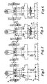
- FIGS. 1-4 show in simplified form the parts of a punch press that are essential for understanding the invention.
- the crank arm 1, the levers 2, the adjusting spindles 3, the drive connecting rods 4, the plunger 5 and the table 6 are drawn from the punch press.
- WHS means the tool closing height.
- the deflection amount F and the play S are shown schematically in accordance with the respective operating states.
- Figure 3 shows the same machine that with a stroke rate of 100 H / min. punches. The speed is therefore again the same as that of FIG. 1.
- the upper tool part 8, the lower tool part 9 and the workpiece, i.e. the tape 10 from which the product is punched and embossed is shown.
- the reference number 13 denotes a punched-out piece of material.
- Figure 4 shows the machine with a high number of strokes, ie analogous to the number of strokes in FIG. 2. Because of the large dynamic forces (at approx. 300-400 H / min.) the game is run through and at the same time the dynamic suspension occurs analogously to FIG. In order to keep the tool closing height WSH constant again, the plunger adjustment would have to be corrected by the amount F + S.
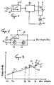
- FIG. 5 schematically shows a block diagram of a known regulation, which is basically based on FIG. 1 of DE-PS 27 31 084.
- the number of strokes is fed from a corresponding sensor 26 to a first element 20, in which a target characteristic curve is stored.
- a target characteristic curve is provided for each tool used.
- the target characteristic is programmable via an input 21 of the control device.
- the target characteristic curve e.g. represents the immersion depth as a function of the number of strokes.
- a comparator the target immersion depth emitted by the element 20 is compared with the actual immersion depth, which is measured by a sensor 25 on the motor 24 of the immersion depth adjustment.
- the element 22 activates one of the switches 23 in order to actuate the motor for the immersion depth adjustment for raising or lowering the ram or tool. The actuation continues until the actual value is again adjusted to the setpoint within the control accuracy.
- FIG. 6 shows roughly schematically how the control device of a punch press according to the invention can be designed. Only one element 30 of the control device is shown, which is basically the element 20 of Figure 5 corresponds. The other elements of FIG. 5 have been omitted from FIG. 6 for the sake of simplicity. These elements 22, 23, 24, 25 are basically of the same design in the control device according to FIG. 6 as in the known control device according to FIG. 5.
- Element 30 also has a tool-specific target characteristic curve of a known type that has been programmed via input 21. It also has an input for a stroke-dependent signal from a sensor 26.
- An input or input means 31 is now provided, by means of which a value can be entered by which the immersion depth is corrected at the number of strokes present at the moment.
- FIG. 7 shows a nominal characteristic curve 40 in an immersion depth / stroke rate diagram. For the sake of simplicity, this nominal characteristic curve is shown as a straight line. While this is correct for a feed device, the target characteristic curve for the immersion depth will usually be parabolic.
- the schematic nominal characteristic curve shows the value to which the immersion depth is adjusted at the respective number of strokes.
- the setpoint characteristic curve can inevitably only be an imperfect image of the complex real function.
- the parts punched according to the nominal characteristic curve can show large deviations from the desired manufacturing tolerance, even - and especially - if the control device according to FIG. 5 follows the nominal value characteristic curve 40.
- the control device of the punch press according to the invention therefore has input 31, into which a value can be entered by which the control device detaches itself from the setpoint characteristic.
- FIG. 7 shows how this manifests itself in the immersion depth / stroke diagram.
- the operator of the stamping press was able to determine that the operation on the associated target characteristic point 42 does not give the desired precision of the stamped parts.
- the control device can receive a correction value via input 31 W can be entered.
- the punch press then operates at the operating point 41, which results from the nominal characteristic curve 40 and the entered correction value W.
- the value W can be entered using a wide variety of means, for example using a numerical keyboard as a digital value, using a variable resistor as an analog value or using ⁇ keys in predetermined small steps. The type of input will depend on the design of the control device.
- W can of course be larger or smaller or can also be effective on the other side of the nominal characteristic curve, so that an operating point 43 would result. If the precision of the parts achieved at the new operating point 41 is not satisfactory, a different value for W can of course be entered.
- the value W is automatically changed by the control device. This can be done continuously, so that there is again a continuous curve (shown as curve 44 in dashed lines) between the stroke numbers H1 to H4 or H max to H min . This can be done in such a way that an additional characteristic curve is calculated from the known nominal value characteristic curve parameters, which in the example shown passes through the new operating point 41 and touches or intersects the nominal value characteristic curve at the minimum number of strokes.
- corrected correction values W2 to W4 only for individual stroke numbers H2 to H4, the new "operating setpoint curve" which arises, for example, being step-like or being formed between the points by a straight line.
- the nominal characteristic curve 40 is parabolic for the immersion depth, and when it is changed, all parabolic parameters are recalculated starting from the value W set at any number of strokes, and a new nominal nominal characteristic curve is thus formed.
- the control device is of course preferably formed by a digital process control, which carries out the necessary calculations and the corresponding regulation.
- FIG. 6 indicates, for example, how a configuration of the control device according to the invention can be achieved with little effort.
- the signal at the output 33 to the comparator 22 is formed in such a way that an adder / subtractor 35 links the basic value from the setpoint characteristic curve with the entered value W in order to obtain the new operating point.
- a second adder / subtractor 36 is activated, which from the previous new operating point 41 e.g. counts a constant K when the number of strokes drops or adds the constant K when the number of strokes increases.
- the control device is preferably provided with a memory in which at least one value W, at most the entire new target operating characteristic and a number associated with the tool, can be stored are. This makes it possible to call up a tool that has already been used and has been driven with a changed setpoint characteristic curve and to start operation on the changed curve.
- the above statements regarding the immersion depth also apply to the feed length.
- the corresponding setpoint characteristic curve can be a straight line.
- the principle of correction and the means used remain the same.
- only one of the corrections that is, either the feed length or the immersion depth, can be carried out on a punch press.
- both options are provided in the same punch press.
Abstract
Description
Die vorliegende Erfindung betrifft eine Stanzpresse mit Hubzahlverstellung und einer eine Sollkennlinie enthaltenden Steuer- bzw. Regeleinrichtung, durch welche Signale für eine Einstelleinrichtung gemäss der Sollkennlinie erzeugbar sind, und durch welche Einstellrichtung eine Eintauchtiefeneinstellung des Stössels der Stanzpresse bei laufender Stanzpresse in Abhängigkeit von den Signalen aus der Steuer- bzw. Regeleinrichtung stattfindet.The present invention relates to a punch press with stroke rate adjustment and a control device which contains a target characteristic, by means of which signals for an adjusting device can be generated according to the target characteristic, and by which setting direction an immersion depth adjustment of the punch of the punch press while the punch press is running, depending on the signals the control or regulating device takes place.
Ferner betrifft die Erfindung eine Stanzpresse mit Hubzahlverstellung und einer eine Sollkennlinie enthaltenden Steuer- bzw. Regeleinrichtung, durch welche Signale für eine Einstelleinrichtung gemäss der Sollkennlinie erzeugbar sind und durch welche Einstelleinrichtung eine Vorschublängeneinstellung für das zu stanzende Material bei laufender Stanzpresse in Abhängigkeit von den Signalen aus der Steuer- bzw. Regeleinrichtung stattfindet.Furthermore, the invention relates to a punch press with stroke rate adjustment and a control device containing a target characteristic, by means of which signals for an adjusting device according to the target characteristic can be generated and by which adjusting device a feed length setting for the material to be punched while the punch press is running as a function of the signals the control or regulating device takes place.
In Stanzpressen bewirken Aenderungen der Betriebsparameter wie z.B. Hubzahl, Werkzeuge und Werkstücke grundsätzlich Abweichungen von vorgegebenen Sollwerten. Aenderungen der Hubzahlen wirken sich dahingehend aus, dass sich die Trägheitskräfte ändern, z.B. steigen die Trägheitskräfte mit zunehmenden Hubzahlen. Damit entstehen durch kleine, elastische Aenderungen der Abmessungen bewegter Teile der Presse und auch durch die Aenderung der Spiele in Lagerungen Aenderungen der Werkzeugschlusshöhe, bzw. der Eintauchteiefe der Werkzeuge. Unterschied liche Werkzeuge, die sich in bezug auf ihre Masse voneinander unterscheiden, bewirken im Betrieb ebenfalls unterschiedliche Trägheitskräfte, die gegebenenfalls mit den vorgenannten Trägheitskräften summiert, weiter zu Abweichungen der vorgegebenen Sollwerte führen. Spezifisch in bezug auf die Eintauchtiefe spielt die Beschaffenheit des zu verarbeitenden Rohlings, z.B. dessen metallurgische Eigenschaften, sowie die Fertigung selbst, bzw. die Form eines anzufertigenden Werkstückes, eine grosse Rolle.In punching presses, changes in operating parameters such as the number of strokes, tools and workpieces always cause deviations from specified target values. Changes in the number of strokes have the effect that the inertial forces change, for example the inertial forces increase with increasing number of strokes. Small, elastic changes in the dimensions of moving parts of the press and changes in play in the bearings result in changes in the height of the tool, or the depth of immersion of the tools. difference Liche tools, which differ from each other in terms of their mass, also cause different inertia forces during operation, which, if necessary, add up with the aforementioned inertia forces, further lead to deviations from the specified target values. Specifically with regard to the immersion depth, the nature of the blank to be processed, for example its metallurgical properties, as well as the manufacture itself or the shape of a workpiece to be manufactured, play a major role.
Sollwertabweichungen entstehen auch in der Vorschubeinrichtung, bei der das Mass der Vorschublänge von einem jeweils vorgegebenen Sollwert abweicht, wobei hier zunehmende Hubzahl und beschleunigte Bandmasse weitere Fehlerquellen bilden.Setpoint deviations also occur in the feed device, in which the dimension of the feed length deviates from a respectively predetermined setpoint, with increasing number of strokes and accelerated belt mass forming further sources of error.
Aus der DE-PS 27 31 084 ist es bekannt, eine Stanzpresse mit während dem Betrieb verstellbarer Eintauchtiefe des Stössels bzw. des Werkzeuges mit einer Steuer- bzw. Regeleinrichtung zu versehen. In diese Steuer- bzw. Regeleinrichtung ist eine Kennlinie eingegeben, welche die Funktion Eintauchtiefe in Abhängigkeit von der Hubzahl pro Minute der Stanzpresse wiedergeben soll. Diese Kennlinie dient als Sollwert. Der gemessene Eintauchtiefenistwert wird mit diesem Sollwert verglichen. Bei einer Abweichung des Istwertes erfolgt durch die Steuer- bzw. Regeleinrichrichtung eine Korrektur in Richtung auf den Sollwert.From DE-PS 27 31 084 it is known to provide a punch press with an adjustable immersion depth of the ram or the tool with a control device. A characteristic curve is entered into this control or regulating device, which is intended to represent the immersion depth function as a function of the number of strokes per minute of the punch press. This characteristic curve serves as the setpoint. The measured immersion depth actual value is compared with this nominal value. If the actual value deviates, the control or regulating device carries out a correction in the direction of the setpoint.
In der Praxis hat es sich indes gezeigt, dass eine solche Steuerung oder Regelung nicht immer zu befriedigenden Ergebnissen führt. Dies liegt daran, dass die tatsächlichen Betriebsgrössen einer Presse sehr komplexen Aenderungen während des Durchlaufens des Hubzahlbereiches unterliegen, was nachfolgend noch näher erläutert werden wird. Oftmals vermag daher die genannte Steuer- bzw. Regeleinrichtung keine befriedigenden Ergebnisse über den gesamten Hubzahlbereich zu liefern. Dies gilt um so mehr, da das Bestreben besteht, Stanzpresserzeugnisse mit höherer Präzision herstellen zu können.In practice, however, it has been shown that such control or regulation does not always lead to satisfactory results. This is because the actual operating sizes of a press are subject to very complex changes during the passage of the stroke rate range, which will be explained in more detail below. The control device mentioned above is therefore often unable to deliver satisfactory results over the entire stroke rate range. This is all the more true since there is a desire to be able to produce stamped products with greater precision.
Hier will die Erfindung Abhilfe schaffen. Die Erfindung, wie sie in den Ansprüchen gekennzeichnet ist, löst die Aufgabe eine Stanzpresse zu schaffen, bei welcher diese Nachteile nicht auftreten und bei welcher mit jedem Werkzeug Teile mit der angestrebten Präzision über den ganzen Hubzahlbereich fertigbar sind, indem die Steuer- bzw. Regeleinrichtung ein Eingabemittel aufweist, mittels welchem ein von der Sollkennlinie abweichender Wert für die Eintauchtiefe bei einer beliebigen Hubzahl eingebbar ist, und dass die Steuer- bzw. Regeleinrichtung zur Erzeugung der Signale derart ausgebildet ist, dass der eingegebene Wert hubzahlabhängig änderbar ist und mit der Sollkennlinie verknüpfbar ist.The invention seeks to remedy this. The invention as characterized in the claims solves the task of creating a punch press in which these disadvantages do not occur and in which parts can be produced with the desired precision over the entire range of strokes with each tool, in that the control device has an input means by means of which a value deviating from the target characteristic curve can be entered for the immersion depth at any number of strokes, and that the control or regulating device for generating the signals is designed in such a way that the entered value can be changed as a function of the stroke number and can be linked to the desired characteristic curve.
Wie vorstehend beschrieben, stellt sich grundsätzlich dieselbe Aufgabe auch in bezug auf die Vorschublänge für das zu stanzende Material. Diese Aufgabe wird für den Vorschub mittels derselben allgemeinen erfinderischen Idee bei einer Stanzmaschine der eingangs zweitgenannten Art dadurch gelöst, dass die Steuer- bzw. Regeleinrichtung ein Eingabemittel aufweist, mittels welchem ein von der Sollkennlinie abweichender Wert für die Vorschublänge bei einer beliebigen Hubzahl eingebbar ist, und dass die Steuer- bzw. Regeleinrichtung zur Erzeugung der Signale derart ausgebildet ist, dass der eingegebene Wert hubzahlabhängig änderbar ist und mit der Sollkennlinie verknüpfbar ist.As described above, basically the same task also arises with regard to the feed length for the material to be punched. This object is achieved for the feed by means of the same general inventive idea in a punching machine of the type mentioned at the outset in that the control or regulating device has an input means by means of which a value for the feed length deviating from the nominal characteristic curve can be entered at any number of strokes and that the control or regulating device for generating the signals is designed in such a way that the entered value can be changed depending on the stroke rate and can be linked to the target characteristic curve.
Mittels der erfindungsgemässen Stanzpresse lassen sich präzise Stanzteile über den gesamten Hubzahlbereich fertigen. Wird - wie bekannt - von einer geringen Hubzahl von z.B. 100 Hüben pro Minute als Einrichthubzahl entlang der werkzeugspezifischen Sollkennlinie auf die gewünschte Hubzahl hochgefahren, so werden Eintauchtiefenfehler bei einer hohen Hubzahl an den Stanzteilen sicht- und messbar. Durch die Eingabe eines Wertes als Korrektur für die Eintauchtiefe kann der Fehler bei der angefahrenen Drehzahl sicht- und messbar verringert werden. Die Steuerung bzw. Regelung verlässt dabei die an sich vorgegebene Sollkennlinie. Wird nun die Hubzahl wieder verändert, so wird von der Steuer- bzw. Regeleinrichtung ein neuer Sollwert gebildet. Dabei wird der eingegebene Wert von der Einrichtung geändert und zusammen mit der fixen Sollwertkennlinie zur Bestimmung der für die neue Hubzahl geeigneten Eintauchtiefe verwendet.Using the punch press according to the invention, precise punched parts can be produced over the entire stroke rate range. If - as is known - a low number of strokes of, for example, 100 strokes per minute is used to set the desired number of strokes along the tool-specific characteristic curve, immersion depth errors with a high number of strokes on the stamped parts become visible and measurable. By entering a value as a correction for the immersion depth, the error when the speed is approached can be visibly and measurably reduced. The open-loop or closed-loop control leaves the target characteristic curve that is predetermined per se. If the number of strokes is changed again, the control device regulates a new setpoint. The entered value is changed by the device and together with the fixed setpoint characteristic used to determine the immersion depth suitable for the new stroke rate.
Analog geht die Steuer- bzw. Regeleinrichtung bei der Aenderung des Sollvorschublängenwertes vor.The control or regulating device proceeds analogously when changing the target feed length value.
Im folgenden wird die Erfindung anhand von lediglich einen Ausführungsweg darstellenden Zeichnungen näher erläutert.The invention is explained in more detail below with the aid of drawings which illustrate only one embodiment.
Es zeigen:
- Figuren 1-4 vereinfacht die hauptsächlichsten bewegten Teile einer Stanzpresse;
Figur 5 ein Diagramm einer bekannten Regelungseinrichtung;Figur 6 eine erfindungsgemässe Regelungseinrichtung, und- Figur 7 eine Kennlinie zur Illustration der Wirkung der Regelungseinrichtung gemäss
Figur 6.
- Figures 1-4 simplify the main moving parts of a punch press;
- Figure 5 is a diagram of a known control device;
- 6 shows a control device according to the invention, and
- FIG. 7 shows a characteristic curve to illustrate the effect of the control device according to FIG. 6.
Vorerst wird anhand der Figuren 1-4, die vereinfacht die zum Verständnis der Erfindung wesentlichsten Teile einer Stanzpresse zeigen, die Problematik in bezug auf die Eintauchtiefe erklärt. Von der Stanzpresse sind der Kurbelarm 1, die Hebel 2, die Verstellspindeln 3, die Antriebspleuel 4, der Stössel 5 und der Tisch 6 gezeichnet. WHS bedeutet die Werkzeugschliesshöhe. Weiter sind durch Durchfederungsbetrag F sowie das Spiel S entsprechend den jeweiligen Betriebszuständen schematisch dargestellt.For the time being, the problems relating to the immersion depth are explained with reference to FIGS. 1-4, which show in simplified form the parts of a punch press that are essential for understanding the invention. The
In der Figur 1 ist nun eine Presse dargestellt, die mit einer Hubzahl von 100 H/min. und ohne Werkzeug im Betrieb steht. Dabei sind die verschiedenen Lager 7 als Zapfenlager gezeichnet und das jeweils darin vorhandene Spiel ist übertrieben gross dargestellt. Sämtliche Bauteile, insbesondere Hebel 2, wirken als starre Bauteile, sind also nicht verformt. Die relative Stellung von Lagerzapfen und Lagerbüchse, also der Ort des Spieles im Lager, ist lediglich durch den Stössel 5, d.h. durch sein Gewicht, bestimmt. Es ist ersichtlich, dass sämtliche Bauteile durch den Stössel 5 "nach unten" gezogen sind. Die Werkzeugschliesshöhe WSH entspricht der vorgegebenen Soll-Werkzeugschliesshöhe.In Figure 1, a press is now shown, which with a stroke rate of 100 H / min. and is in operation without tools. The various bearings 7 are drawn as journal bearings and the game in each case is exaggerated. All components, in particular lever 2, act as rigid components and are therefore not deformed. The relative position of the bearing journal and the bearing bush, that is to say the location of the play in the bearing, is only determined by the
In der Figur 2 ist dieselbe Maschine bei relativ hoher Drehzahl, bzw. hoher Hubzahl, beispielsweise 1500 H/min. und wieder ohne Werkzeug vereinfacht dargestellt. Aufgrund dieser hohen Hubzahl entstehen elastische Verformungen von Arbeitsteilen, die sogenannte dynamische Federung. Diese ist in der Figur 2 schematisch als Durchbiegung der Hebel 2 dargestellt. Jetzt muss aber die Werkzeugschliesshöhe WSH konstant gehalten werden, da diese schliesslich auf die Eintauchtiefe Auswirkungen hat. Um diese Werkzeugschlusshöhe WSH bei der gezeigten dynamischen Federung konstant zu halten, müsste also eine Korrektur der Stösselhöhe um denjenigen Betrag durchgeführt werden, welcher der dynamischen Federung entspricht. Das heisst, es müsste eine Höhenkorrektur durchgeführt werden, die dem Durchfederungsbetrag gleich ist.In Figure 2, the same machine is at a relatively high speed or high number of strokes, for example 1500 H / min. and again shown simplified without tools. This high number of strokes creates elastic deformations of work parts, the so-called dynamic suspension. This is shown schematically in FIG. 2 as the deflection of the levers 2. However, the tool closing height WSH must now be kept constant, since this ultimately has an effect on the immersion depth. In order to keep this tool closing height WSH constant in the dynamic suspension shown, the ram height would have to be corrected by the amount that corresponds to the dynamic suspension. This means that a height correction that is equal to the deflection amount would have to be carried out.
Figur 3 zeigt dieselbe Maschine, die mit einer Hubzahl von 100 H/min. stanzt. Die Drehzahl ist also wieder gleich derjenigen der Figur 1. Zusätzlich sind hier nun der Werkzeugoberteil 8, der Werkzeugunterteil 9 sowie das Werkstück, d.h. das Band 10, aus dem das Produkt gestanzt und geprägt wird, dargestellt. Mit der Bezugsziffer 13 ist ein ausgestanztes Materialstück bezeichnet.Figure 3 shows the same machine that with a stroke rate of 100 H / min. punches. The speed is therefore again the same as that of FIG. 1. In addition, the upper tool part 8, the lower tool part 9 and the workpiece, i.e. the
Aufgrund der tiefen Drehzahl von z.B. 100 H/min. treten analog zum Stand der Figur 1 keine dynamischen Kräfte in der Maschine auf. Jedoch treten aufgrund der Stanzung, Prägung, d.h. allgemein der Bearbeitung, Kräfte auf, welche gemäss der Darstellung in der Figur 3 aufwärts gerichtet sind, welcher Zustand durch die schematischen Darstellungen der einzelnen Lager und die Stellung der Hebel illustriert ist. Die Fehlerquelle hier sind die Spiele, insbesondere in den Lagern. Um nun eine einwandfreie Stanzung ausführen zu können, müsste zuerst das gesamte Spiel aufgehoben werden. Da hier der Stössel "nach oben" gedrückt wird, müsste folglicherweise die Stösselverstellung um den Betrag s nach unten verstellt werden, so dass wieder die vorgegebene Werkzeugschliesshöhe WSH eingehalten werden kann.Due to the low speed of e.g. 100 h / min. analogous to the state of FIG. 1, no dynamic forces occur in the machine. However, due to the punching, embossing, i.e. generally the processing, forces which, as shown in FIG. 3, are directed upwards, which state is illustrated by the schematic representations of the individual bearings and the position of the levers. The source of errors here are the games, especially in the camps. In order to be able to perform a perfect punching, the entire game would first have to be saved. Since the plunger is "pushed up" here, the plunger adjustment would consequently have to be adjusted downwards by the amount s, so that the specified tool closing height WSH can again be maintained.
Figur 4 zeigt die Maschine bei hoher Hubzahl, also analog der Hubzahl der Figur 2. Durch die grossen dynamischen Kräfte wird (bei ca. 300-400 H/min.) das Spiel durchfahren und gleichzeitig tritt wieder die dynamische Federung analog der Figur 2 auf. Um nun die Werkzeugschliesshöhe WSH wiederum kontant zu halten, müsste mittels der Stösselverstellung die Eintauchtiefe um den Betrag F + S korrigiert werden.Figure 4 shows the machine with a high number of strokes, ie analogous to the number of strokes in FIG. 2. Because of the large dynamic forces (at approx. 300-400 H / min.) the game is run through and at the same time the dynamic suspension occurs analogously to FIG. In order to keep the tool closing height WSH constant again, the plunger adjustment would have to be corrected by the amount F + S.
Aus den obigen Erklärungen geht somit hervor, dass abhängig von der Hubzahl, vom Werkzeug und auch vom Werkstück (z.B. metallurgische Eigneschaften) der Stössel eine jeweils andere Höhenstellung einnehmen muss. Auch muss festgehalten werden, dass bei Eintauchtiefenmessungen ohne Stanzvorgang die Höhenstellung ungenau ist.From the explanations above it is clear that depending on the number of strokes, the tool and also the workpiece (e.g. metallurgical properties) the ram must have a different height position. It must also be noted that the height position is inaccurate for immersion depth measurements without punching.
Figur 5 zeigt schematisch ein Blockdiagramm einer bekannten Regelung, welches grundsätzlich auf der Figur 1 der DE-PS 27 31 084 beruht. Die Hubzahl wird dabei von einem entsprechenden Sensor 26 einem ersten Element 20 zugeführt, in welchem eine Sollkennlinie gespeichert ist. Für jedes verwendete Werkzeug ist eine solche Sollkennlinie vorgesehen. Die Sollkennlinie ist über einen Eingang 21 der Regeleinrichtung programmierbar. Die Sollkennlinie stellt z.B. die Eintauchtiefe als Funktion der Hubzahl dar. In einem zweiten Element 22, einem Vergleicher, wird die vom Element 20 abgegebene Solleintauchtiefe mit der Isteintauchtiefe verglichen, welche von einem Sensor 25 am Motor 24 der Eintauchtiefenverstellung abgenommen wird. Weicht die Isteintauchtiefenverstellung um einen vorgegebenen Schwellwert von der Solleintauchtiefe ab, so aktiviert das Element 22 einen der Schalter 23, um den Motor der Eintauchtiefenverstellung zur Höher- oder Tieferstellung des Stössels bzw. Werkzeuges zu betätigen. Die Betätigung erfolgt so lange, bis der Istwert im Rahmen der Regelgenauigkeit wieder an den Sollwert angeglichen ist.FIG. 5 schematically shows a block diagram of a known regulation, which is basically based on FIG. 1 of DE-PS 27 31 084. The number of strokes is fed from a corresponding
Figur 6 zeigt grob schematisch, wie die Regelungseinrichtung einer erfindungsgemässen Stanzpresse ausgeführt sein kann. Gezeigt ist dabei nur ein Element 30 der Regelungseinrichtung, welches grundsätzlich dem Element 20 von Figur 5 entspricht. Die weiteren Elemente von Figur 5 sind in Figur 6 der Einfachheit halber weggelassen worden. Diese Elemente 22,23,24,25 sind bei der Regeleinrichtung nach Figur 6 grundsätzlich gleich ausgeführt, wie bei der bekannten Regeleinrichtung nach Figur 5.FIG. 6 shows roughly schematically how the control device of a punch press according to the invention can be designed. Only one
Auch das Element 30 weist eine werkzeugspezifische Sollkennlinie bekannter Art auf, die über den Eingang 21 programmiert worden ist. Ebenfalls weist sie einen Eingang für ein hubzahlabhängiges Signal von einem Sensor 26 auf. Es ist nun indes ein Eingang bzw. Eingabemittel 31 vorgesehen, mittels welchem ein Wert eingegeben werden kann, um welchen die Eintauchtiefe bei der im Moment vorliegenden Hubzahl korrigiert wird. Es soll dies mit Bezug auf Figur 7 näher erläutert werden, welche eine Sollkennlinie 40 in einem Eintauchtiefe/Hubzahldiagramm zeigt. Diese Sollkennlinie ist der Einfachheit halber als Gerade gezeigt. Während dies für eine Vorschubeinrichtung richtig ist, wird die Sollkennlinie für die Eintauchtiefe in der Regel aber parabelförmig verlaufen. Die schematische Sollkennlinie zeigt, auf welchen Wert der Eintauchtiefe bei der jeweiligen Hubzahl eingeregelt wird.
Aus der vorgängigen Diskussion der Figuren 1-4 ist aber erkennbar, dass die Sollwertkennlinie zwangsläufig nur ein unvollkommenes Abbild der komplexen realen Funktion sein kann. Entsprechend können die gemäss der Sollkennlinie gestanzten Teile grosse Abweichungen von der gewünschten Fertigungstoleranz zeigen, auch - und gerade - wenn die Regeleinrichtung nach Figur 5 der Sollwertkennlinie 40 folgt. Die Steuereinrichtung der erfindungsgemässen Stanzpresse weist daher den Eingang 31 auf, in welchen ein Wert eingebbar ist, um welchen sich die Steuereinrichtung von der Sollwertkennlinie löst.However, it can be seen from the previous discussion of FIGS. 1-4 that the setpoint characteristic curve can inevitably only be an imperfect image of the complex real function. Correspondingly, the parts punched according to the nominal characteristic curve can show large deviations from the desired manufacturing tolerance, even - and especially - if the control device according to FIG. 5 follows the nominal value
In Figur 7 ist gezeigt, wie sich dies im Eintauchtiefe-Hubzahldiagramm äussert. Bei der Hubzahl H₁ hat die Bedienungsperson der Stanzpresse feststellen können, dass der Betrieb auf dem zugehörigen Sollkennlinienpunkt 42 keine gewünschte Präzision der Stanzteile ergibt. Ueber den Eingang 31 kann der Regeleinrichtung ein Korrekturwert W eingegeben werden. Die Stanzpresse arbeitet dann im Betriebspunkt 41, welcher sich aus der Sollkennlinie 40 und dem eingegebenen Korrekturwert W ergibt. Der Wert W kann mit verschiedensten Mitteln eingegeben werden, z.B. mit einer numerischen Tastatur als Digitalwert, mit einem veränderbaren Widerstand als Analogwert oder mit ±-Tasten in vorbestimmten kleinen Schritten. Die Art der Eingabe wird sich dabei nach der Ausgestaltung der Regelungseinrichtung richten.FIG. 7 shows how this manifests itself in the immersion depth / stroke diagram. At the number of
Das dargestellte Beispiel zeigt den Wert W nur grundsätzlich; natürlich kann W grösser oder kleiner sein oder auch auf der andseren Seite der Sollkennlinie wirksam werden, so dass sich ein Betriebspunkt 43 ergäbe. Falls die im neuen Betriebspunkt 41 erzielte Präzision der Teile nicht zufriedenstellend ist, kann natürlich ein anderer Wert für W eingegeben werden.The example shown basically shows the value W; W can of course be larger or smaller or can also be effective on the other side of the nominal characteristic curve, so that an operating point 43 would result. If the precision of the parts achieved at the new operating point 41 is not satisfactory, a different value for W can of course be entered.
Wird nun die Hubzahl geändert, so wird der Wert W von der Regeleinrichtung selbsttätig geändert. Dies kann kontinuierlich erfolgen, so dass sich zwischen den Hubzahlen H₁ bis H₄ bzw. Hmax bis Hmin wieder eine kontinuierliche Kurve (als Kurve 44 strichliniert dargestellt) ergibt. Dies kann so erfolgen, dass aus den bekannten Sollwertkennlinienparametern eine zusätzliche Kennlinie errechnet wird, welche im gezeigten Beispiel durch den neuen Betriebspunkt 41 geht und bei der minimalen Hubzahl die Sollwertkennlinie berührt oder schneidet. Es können aber auch nur für einzelne Hubzahlen H₂ bis H₄ geänderte Korrekturwerte W₂ bis W₄ gebildet werden, wobei die entstehende neue "Betriebssollwertkurve" z.B. treppenartig verläuft oder zwischen den Punkten durch eine Gerade gebildet wird.If the number of strokes is now changed, the value W is automatically changed by the control device. This can be done continuously, so that there is again a continuous curve (shown as
Vorzugsweise verläuft die Sollkennlinie 40 für die Eintauchtiefe parabelförmig, und bei der Aenderung derer werden ausgehend vom bei einer beliebigen Hubzahl eingestellten Wert W alle Parabelparameter neu berechnet, und es wird eine damit neue Betriebssollkennlinie gebildet. Für diesen Fall wird die Regeleinrichtung natürlich vorzugsweise von einer digitalen Prozesssteuerung gebildet, welche die nötigen Berechnungen und die entsprechende Regelung durchführt.Preferably, the nominal
In Figur 6 ist aber beispielsweise angedeutet, wie mit wenig Aufwand eine erfindungsgemässe Ausgestaltung der Regeleinrichtung grundsätzlich erzielbar ist. Dabei wird das Signal am Ausgang 33 zum Vergleicher 22 so gebildet, dass ein Addierer/Subtrahierer 35 den Grundwert aus der Sollwertkennlinie mit dem eingegebenen Wert W verknüpft, um den neuen Arbeitspunkt zu erhalten. Bei sich ändernder Hubzahl wird ein zweiter Addierer/Subtrahierer 36 aktiviert, welcher vom bisherigen neuen Betriebspunkt 41 z.B. eine Konstante K abzählt, wenn die Hubzahl fällt bzw. die Kontante K dazuzählt, wenn die Hubzahl steigt.However, FIG. 6 indicates, for example, how a configuration of the control device according to the invention can be achieved with little effort. The signal at the output 33 to the
Da die Werte W bzw. die neue Betriebssollkennlinie für ein bestimmtes Werkzeug in der Regel über einige Zeit gültig sind, ist die Steuereinrichtung vorzugsweise mit einem Speicher versehen, in welchem mindestens ein Wert W, allenfalls die ganze neue Betriebssollkennlinie und eine dem Werkzeug zugehörige Nummer speicherbar sind. Damit ist es möglich, für ein bereits einmal verwendetes Werkzeug, welches mit einer geänderten Sollwertkennlinie gefahren worden ist, diese direkt wieder aufzurufen und den Betrieb gerade auf der geänderten Kurve aufzunehmen.Since the values W or the new target operating characteristic are generally valid for a certain time for a certain tool, the control device is preferably provided with a memory in which at least one value W, at most the entire new target operating characteristic and a number associated with the tool, can be stored are. This makes it possible to call up a tool that has already been used and has been driven with a changed setpoint characteristic curve and to start operation on the changed curve.
Das vorstehend zu der Eintauchtiefe ausgeführte gilt auch für die Vorschublänge. Die entsprechende Sollwertkennlinie kann dabei eine Gerade sein. Das Prinzip der Korrektur und die verwendeten Mittel bleiben sich aber gleich. Natürlich kann bei einer Stanzpresse auch nur eine der Korrekturen, also entweder der Vorschublänge oder der Eintauchtiefe ausführbar sein. Vorzugsweise sind aber beide Möglichkeiten in derselben Stanzpresse vorgesehen.The above statements regarding the immersion depth also apply to the feed length. The corresponding setpoint characteristic curve can be a straight line. The principle of correction and the means used remain the same. Of course, only one of the corrections, that is, either the feed length or the immersion depth, can be carried out on a punch press. Preferably, however, both options are provided in the same punch press.
Claims (8)
Applications Claiming Priority (1)
| Application Number | Priority Date | Filing Date | Title |
|---|---|---|---|
| CH4039/88A CH676445A5 (en) | 1988-10-28 | 1988-10-28 |
Publications (2)
| Publication Number | Publication Date |
|---|---|
| EP0428780A1 true EP0428780A1 (en) | 1991-05-29 |
| EP0428780B1 EP0428780B1 (en) | 1993-12-22 |
Family
ID=4268678
Family Applications (1)
| Application Number | Title | Priority Date | Filing Date |
|---|---|---|---|
| EP89121629A Expired - Lifetime EP0428780B1 (en) | 1988-10-28 | 1989-11-23 | Punch press with correction value input for the penetration depth and the feed length |
Country Status (4)
| Country | Link |
|---|---|
| US (1) | US5099731A (en) |
| EP (1) | EP0428780B1 (en) |
| CH (1) | CH676445A5 (en) |
| DE (1) | DE58906506D1 (en) |
Cited By (2)
| Publication number | Priority date | Publication date | Assignee | Title |
|---|---|---|---|---|
| EP0496270A1 (en) * | 1991-01-21 | 1992-07-29 | OTTO KAISER GmbH & Co. KG | Process for holding the length of feed constant |
| EP1177886A1 (en) * | 2000-08-01 | 2002-02-06 | Haulick + Roos GmbH | Automatic pressing or punching machine |
Families Citing this family (4)
| Publication number | Priority date | Publication date | Assignee | Title |
|---|---|---|---|---|
| US6868351B1 (en) * | 1999-10-19 | 2005-03-15 | The Minster Machine Company | Displacement based dynamic load monitor |
| US6582166B1 (en) | 1999-10-22 | 2003-06-24 | Gerber Scientific Products, Inc. | Method of compensating for cutter deflection |
| KR200353163Y1 (en) * | 2004-03-26 | 2004-06-14 | 디앤크래프트 주식회사 | Punch capable of punching and embossing simultaneously |
| EP1879266B1 (en) * | 2006-07-13 | 2013-03-20 | Schäfer Werkzeug- und Sondermaschinenbau GmbH | Method and device for adjusting the stroke movement in a crimping device |
Citations (2)
| Publication number | Priority date | Publication date | Assignee | Title |
|---|---|---|---|---|
| GB1099192A (en) * | 1964-01-15 | 1968-01-17 | Hordern Mason & Edwards Ltd | Improvements relating to feeding devices for power presses or like machine tools |
| FR2396641A1 (en) * | 1977-07-09 | 1979-02-02 | Schuler Gmbh L | POSITIONING MECHANISM FOR A SLIDING ADJUSTMENT OF A CUTTING PRESS |
Family Cites Families (4)
| Publication number | Priority date | Publication date | Assignee | Title |
|---|---|---|---|---|
| GB2099750B (en) * | 1981-06-06 | 1985-06-26 | Samco Strong Ltd | Stroke control for press |
| EP0084271B1 (en) * | 1982-01-08 | 1986-11-05 | Fanuc Ltd. | A spindle head unit |
| DE3432235A1 (en) * | 1984-09-01 | 1986-03-13 | Unidor GmbH, 7534 Birkenfeld | Method for holding constant a preselected feed length of a strip feed device on a machine tool |
| US4823658A (en) * | 1985-10-18 | 1989-04-25 | Spicer Andrew I | Punch presses |
-
1988
- 1988-10-28 CH CH4039/88A patent/CH676445A5/de not_active IP Right Cessation
-
1989
- 1989-11-23 DE DE89121629T patent/DE58906506D1/en not_active Expired - Lifetime
- 1989-11-23 EP EP89121629A patent/EP0428780B1/en not_active Expired - Lifetime
- 1989-12-11 US US07/450,285 patent/US5099731A/en not_active Expired - Lifetime
Patent Citations (2)
| Publication number | Priority date | Publication date | Assignee | Title |
|---|---|---|---|---|
| GB1099192A (en) * | 1964-01-15 | 1968-01-17 | Hordern Mason & Edwards Ltd | Improvements relating to feeding devices for power presses or like machine tools |
| FR2396641A1 (en) * | 1977-07-09 | 1979-02-02 | Schuler Gmbh L | POSITIONING MECHANISM FOR A SLIDING ADJUSTMENT OF A CUTTING PRESS |
Non-Patent Citations (1)
| Title |
|---|
| WERKSTATT UND BETRIEB, Band 112, Nr. 4, April 1979, Seiten 269-273, München, DE; H. HOFFMANN et al.: "Regeleinrichtung für konstante Eintauchtiefe beim Schneiden" * |
Cited By (2)
| Publication number | Priority date | Publication date | Assignee | Title |
|---|---|---|---|---|
| EP0496270A1 (en) * | 1991-01-21 | 1992-07-29 | OTTO KAISER GmbH & Co. KG | Process for holding the length of feed constant |
| EP1177886A1 (en) * | 2000-08-01 | 2002-02-06 | Haulick + Roos GmbH | Automatic pressing or punching machine |
Also Published As
| Publication number | Publication date |
|---|---|
| EP0428780B1 (en) | 1993-12-22 |
| DE58906506D1 (en) | 1994-02-03 |
| US5099731A (en) | 1992-03-31 |
| CH676445A5 (en) | 1991-01-31 |
Similar Documents
| Publication | Publication Date | Title |
|---|---|---|
| CH632157A5 (en) | METHOD FOR PRODUCING TABLETS AND TABLET PRESS FOR CARRYING OUT THE METHOD. | |
| EP2008736B1 (en) | Machine tool and method for discharging a workpiece part | |
| DE3153332C2 (en) | Method for controlling a hydraulic press for pressing wood-based panels and device for carrying out the method | |
| DE3718961C2 (en) | ||
| DE2731084B2 (en) | Slide adjustment for high-speed cutting presses | |
| CH659604A5 (en) | ELECTRIC EROSION DEVICE FOR MACHINING A WORKPIECE. | |
| DE3346282A1 (en) | DEVICE FOR DETERMINING A FINAL POSITION OF THE PRESS OF A PRESS | |
| EP0353479A1 (en) | Method and apparatus for reducing the press load of a cutting press with positive stops | |
| DE3131402A1 (en) | METHOD AND TABLET PRESS FOR THE SUCCESSFUL PRODUCTION OF A VARIETY OF TABLETS OF THE SAME WEIGHT | |
| DE3744177C2 (en) | ||
| EP0428780B1 (en) | Punch press with correction value input for the penetration depth and the feed length | |
| DE112018001401T5 (en) | Press system | |
| DE1752005B2 (en) | Control of the table movements of hydraulic presses | |
| DE3441113A1 (en) | Bending machine with numerical control | |
| DE3715077C2 (en) | ||
| EP0242824B1 (en) | Method and device for the regulation of at least two determinant physical characteristics for the quality of the finished product of a smoking rod | |
| DE4315680C2 (en) | Regulation of tablet parameters during production on rotary presses | |
| EP0732194B1 (en) | Method and apparatus for measuring and regulating the position of the slide in a high-speed cutting press | |
| EP0367035B1 (en) | Press or punching machine | |
| DE2249793C2 (en) | Method and machine for rolling rings | |
| EP1287975B1 (en) | Process for producing molded parts in a powder press | |
| DE1940912C3 (en) | Device for aligning strip material gradually fed to scissors with a scroll cut | |
| DE2805187C2 (en) | Drop forging press | |
| DE2437295A1 (en) | Wire spooling installation - with electronic control for adjusting speed of drum's forward movement | |
| DE102004012858B4 (en) | Roller body manufacturing method for roller bearing, involves measuring weight or volume of raw blocks, and feeding blocks in to pressing tool, where blocks are shaped in tool in two stages and deformed by stamp that penetrates in to tool |
Legal Events
| Date | Code | Title | Description |
|---|---|---|---|
| PUAI | Public reference made under article 153(3) epc to a published international application that has entered the european phase |
Free format text: ORIGINAL CODE: 0009012 |
|
| 17P | Request for examination filed |
Effective date: 19910204 |
|
| AK | Designated contracting states |
Kind code of ref document: A1 Designated state(s): DE FR GB IT NL |
|
| TCNL | Nl: translation of patent claims filed | ||
| EL | Fr: translation of claims filed | ||
| ITCL | It: translation for ep claims filed |
Representative=s name: BARZANO' E ZANARDO ROMA S.P.A. |
|
| GBC | Gb: translation of claims filed (gb section 78(7)/1977) | ||
| 17Q | First examination report despatched |
Effective date: 19930122 |
|
| RAP1 | Party data changed (applicant data changed or rights of an application transferred) |
Owner name: BRUDERER AG |
|
| ITF | It: translation for a ep patent filed |
Owner name: BARZANO' E ZANARDO ROMA S.P.A. |
|
| GRAA | (expected) grant |
Free format text: ORIGINAL CODE: 0009210 |
|
| AK | Designated contracting states |
Kind code of ref document: B1 Designated state(s): DE FR GB IT NL |
|
| REF | Corresponds to: |
Ref document number: 58906506 Country of ref document: DE Date of ref document: 19940203 |
|
| ET | Fr: translation filed | ||
| GBT | Gb: translation of ep patent filed (gb section 77(6)(a)/1977) |
Effective date: 19940203 |
|
| PLBE | No opposition filed within time limit |
Free format text: ORIGINAL CODE: 0009261 |
|
| STAA | Information on the status of an ep patent application or granted ep patent |
Free format text: STATUS: NO OPPOSITION FILED WITHIN TIME LIMIT |
|
| 26N | No opposition filed | ||
| REG | Reference to a national code |
Ref country code: GB Ref legal event code: IF02 |
|
| PGFP | Annual fee paid to national office [announced via postgrant information from national office to epo] |
Ref country code: NL Payment date: 20081113 Year of fee payment: 20 Ref country code: DE Payment date: 20081121 Year of fee payment: 20 |
|
| PGFP | Annual fee paid to national office [announced via postgrant information from national office to epo] |
Ref country code: IT Payment date: 20081125 Year of fee payment: 20 |
|
| PGFP | Annual fee paid to national office [announced via postgrant information from national office to epo] |
Ref country code: FR Payment date: 20081113 Year of fee payment: 20 |
|
| PGFP | Annual fee paid to national office [announced via postgrant information from national office to epo] |
Ref country code: GB Payment date: 20081117 Year of fee payment: 20 |
|
| REG | Reference to a national code |
Ref country code: GB Ref legal event code: PE20 Expiry date: 20091122 |
|
| NLV7 | Nl: ceased due to reaching the maximum lifetime of a patent |
Effective date: 20091123 |
|
| PG25 | Lapsed in a contracting state [announced via postgrant information from national office to epo] |
Ref country code: NL Free format text: LAPSE BECAUSE OF EXPIRATION OF PROTECTION Effective date: 20091123 |
|
| PG25 | Lapsed in a contracting state [announced via postgrant information from national office to epo] |
Ref country code: GB Free format text: LAPSE BECAUSE OF EXPIRATION OF PROTECTION Effective date: 20091122 |