EP0428439B1 - Anti-roll device for a motor vehicle - Google Patents
Anti-roll device for a motor vehicle Download PDFInfo
- Publication number
- EP0428439B1 EP0428439B1 EP19900403160 EP90403160A EP0428439B1 EP 0428439 B1 EP0428439 B1 EP 0428439B1 EP 19900403160 EP19900403160 EP 19900403160 EP 90403160 A EP90403160 A EP 90403160A EP 0428439 B1 EP0428439 B1 EP 0428439B1
- Authority
- EP
- European Patent Office
- Prior art keywords
- piston
- integral
- thread
- bars
- roll device
- Prior art date
- Legal status (The legal status is an assumption and is not a legal conclusion. Google has not performed a legal analysis and makes no representation as to the accuracy of the status listed.)
- Expired - Lifetime
Links
Images

Classifications
-
- B—PERFORMING OPERATIONS; TRANSPORTING
- B60—VEHICLES IN GENERAL
- B60G—VEHICLE SUSPENSION ARRANGEMENTS
- B60G21/00—Interconnection systems for two or more resiliently-suspended wheels, e.g. for stabilising a vehicle body with respect to acceleration, deceleration or centrifugal forces
- B60G21/02—Interconnection systems for two or more resiliently-suspended wheels, e.g. for stabilising a vehicle body with respect to acceleration, deceleration or centrifugal forces permanently interconnected
- B60G21/04—Interconnection systems for two or more resiliently-suspended wheels, e.g. for stabilising a vehicle body with respect to acceleration, deceleration or centrifugal forces permanently interconnected mechanically
- B60G21/05—Interconnection systems for two or more resiliently-suspended wheels, e.g. for stabilising a vehicle body with respect to acceleration, deceleration or centrifugal forces permanently interconnected mechanically between wheels on the same axle but on different sides of the vehicle, i.e. the left and right wheel suspensions being interconnected
- B60G21/055—Stabiliser bars
- B60G21/0551—Mounting means therefor
- B60G21/0553—Mounting means therefor adjustable
- B60G21/0555—Mounting means therefor adjustable including an actuator inducing vehicle roll
Definitions
- the subject of the present invention is an anti-tilt device for a motor vehicle which makes it possible to straighten the tilted attitude of the vehicle when the latter is subjected to the effect of centrifugal force, for example during a turn.
- This device is of the type comprising an anti-roll bar consisting of two half-bars joined to one another by a rotary actuator, which comprises a piston displaceable in a body, which is cylindrical and integral with one of the half -bar, and means sensitive to the cant of the vehicle to move the piston in this body; such a device is described in document FR-A-1 271 895.
- the device according to the invention is characterized in that the piston has an internal thread suitable for cooperating with a thread formed on a screw arranged coaxially in the body and integral with it as well as an external thread in the opposite direction to that of the internal thread capable of cooperating with a thread provided on a cylindrical sheath rotatably mounted in the body and integral with the other half-bar.
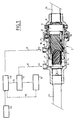
- the anti-roll device comprises an anti-roll bar which consists of two half-bars 1 a and 1 b joined to each other by a designated rotary actuator as a whole by reference 2.
- the cylinder 2 comprises a cylindrical body 3 which is integral with the half-bar 1 a and in which is slidably mounted a piston 4 defining two chambers 5 and 6.
- the chamber 5 communicates by a connector 7 with a conduit 8 connected to a pump 9; on its side the chamber 6 communicates by a connector 10 with a conduit 11 connected to a corrector with hydraulic slide 12; the latter is controlled by a sensor 13 and allows the conduit 11 to be placed in communication either with a conduit 14 connected to the pump 9 to increase the pressure in the chamber 6, or with a conduit 15 connected to a reservoir 16 to reduce the pressure in room 6.
- the piston 4 has an axial thread and is mounted on a screw 17 integral with the body 3 and coaxial with it. Furthermore, it has an external thread of opposite pitch and is mounted in a sheath 18 fitted into the body 1 and secured to a housing 19, itself secured to the half-bar 1b ; the sheath 18 is immobilized laterally by a ball stop 20 which is integral with the sheath and is interposed between the body 3 and a cap 21 screwed onto this body and mounted on the sheath by means of a bearing 22.
- the active surface of the piston 4 in the chamber 5 is practically its annular surface around the screw 17 while that in the chamber 6 is its surface internal to the body 3 and is therefore larger.
- the corrector 12 modifies the pressure P2 and the piston 4 moves longitudinally in the body 3. Due to the mounting of the piston on the screw 17, this piston pivots at the same time by angle ⁇ 1.But due to the helical mounting of the piston in the sheath 18 immobilized longitudinally by the stop 20, the longitudinal displacement of the piston causes a pivoting of an angle ⁇ 2 of the sleeve 18.
- the sleeve 18 pivots with respect to the body 3 by an angle ⁇ 1 + ⁇ 2 and it is the same for the two half-bars 1 a and 1 b which are respectively attached to these elements; this pivoting continues until the superelevation is canceled: the sensor 13 then returns the corrector 12 to the equilibrium position and therefore P2 to its initial value.
Landscapes
- Engineering & Computer Science (AREA)
- Mechanical Engineering (AREA)
- Vehicle Body Suspensions (AREA)
Description
La présente invention a pour objet un dispositif anti-dévers pour véhicule automobile qui permet de redresser l'assiette en dévers du véhicule lorsque celui-ci est soumis à l'effet de la force centrifuge, par exemple au cours d'un virage.The subject of the present invention is an anti-tilt device for a motor vehicle which makes it possible to straighten the tilted attitude of the vehicle when the latter is subjected to the effect of centrifugal force, for example during a turn.
Ce dispositif est du type comprenant une barre anti-roulis constituée de deux demi-barres réunies l'une à l'autre par un vérin rotatif, qui comporte un piston déplaçable dans un corps, qui est cylindrique et solidaire de l'une des demi-barre, et des moyens sensibles au dévers du véhicule pour déplacer le piston dans ce corps; un tel dispositif est décrit dans le document FR-A-1 271 895.This device is of the type comprising an anti-roll bar consisting of two half-bars joined to one another by a rotary actuator, which comprises a piston displaceable in a body, which is cylindrical and integral with one of the half -bar, and means sensitive to the cant of the vehicle to move the piston in this body; such a device is described in document FR-A-1 271 895.
Le dispositif selon l'invention est caractérisé en ce que le piston présente un filetage interne propre à coopérer avec un filetage ménagé sur une vis disposée coaxialement dans le corps et solidaire de celui-ci ainsi qu'un filetage externe de sens inverse de celui du filetage interne et propre à coopérer avec un filetage prévu sur un fourreau cylindrique monté à rotation dans le corps et solidaire de l'autre demi-barre.The device according to the invention is characterized in that the piston has an internal thread suitable for cooperating with a thread formed on a screw arranged coaxially in the body and integral with it as well as an external thread in the opposite direction to that of the internal thread capable of cooperating with a thread provided on a cylindrical sheath rotatably mounted in the body and integral with the other half-bar.
On a décrit ci-après, à titre d'exemple non limitatif, un mode de réalisation du dispositif anti-dévers selon l'invention, avec référence au dessin annexé dans lequel :
- La Figure 1 est un schéma du dispositif, le vérin rotatif étant représenté en coupe axiale;
- La Figure 2 est une autre vue en coupe axiale du vérin rotatif.
- Figure 1 is a diagram of the device, the rotary actuator being shown in axial section;
- Figure 2 is another view in axial section of the rotary actuator.
Tel qu'il est représenté au dessin, le dispositif anti-dévers selon l'invention comprend une barre anti-dévers qui est constituée de deux demi-barres 1a et 1b réunies l'une à l'autre par un vérin rotatif désigné dans son ensemble par la référence 2.As shown in the drawing, the anti-roll device according to the invention comprises an anti-roll bar which consists of two half-
Le vérin 2 comprend un corps cylindrique 3 qui est solidaire de la demi-barre 1a et dans lequel est monté coulissant un piston 4 définissant deux chambres 5 et 6. La chambre 5 communique par un raccord 7 avec un conduit 8 relié à une pompe 9; de son côté la chambre 6 communique par un raccord 10 avec un conduit 11 relié à un correcteur à tiroir hydraulique 12; ce dernier est commandé par un capteur 13 et permet de mettre en communication le conduit 11 soit avec un conduit 14 relié à la pompe 9 pour augmenter la pression dans la chambre 6, soit avec un conduit 15 relié à un réservoir 16 pour diminuer la pression dans la chambre 6.The
Le piston 4 comporte un taraudage axial et est monté sur une vis 17 solidaire du corps 3 et coaxiale à celui-ci. Par ailleurs, il comporte un filetage extérieur de pas contraire et est monté dans un fourreau 18 emmanché dans le corps 1 et solidaire d'un boîtier 19, lui-même solidaire de la demi-barre 1b; le fourreau 18 est immobilisé latéralement par une butée à billes 20 qui est solidaire du fourreau et est interposée entre le corps 3 et un chapeau 21 vissé sur ce corps et monté sur le fourreau par l'intermédiaire d'un roulement 22.The
La surface active du piston 4 dans la chambre 5 est pratiquement sa surface annulaire autour de la vis 17 alors que celle dans la chambre 6 est sa surface intérieure au corps 3 et est donc plus grande.The active surface of the
En position neutre d'équilibre, le piston 4 est sensiblement au milieu de sa course totale; dans cette position, l'équilibre des forces de part et d'autre du piston 4 est donné par la relation P2 S2 = P1 S1, la pression régulée P2 est donc plus faible que la pression d'alimentation P1.In the neutral equilibrium position, the
Lorsqu'il y a modification du dévers du véhicule, le correcteur 12 modifie la pression P2 et le piston 4 se déplace longitudinalement dans le corps 3. Du fait du montage du piston sur la vis 17, ce piston pivote en même temps d'un angle α1.Mais du fait du montage hélicoïdal du piston dans le fourreau 18 immobilisé longitudinalement par la butée 20, le déplacement longitudinal du piston entraîne un pivotement d'un angle α2 du fourreau 18. En définitive le fourreau 18 pivote par rapport au corps 3 d'un angle α1 + α2 et il en est de même des deux demi-barres 1a et 1b qui sont respectivement solidaires de ces éléments; ce pivotement se poursuit jusqu'à ce que le dévers soit annulé : le capteur 13 ramène alors le correcteur 12 en position d'équilibre et donc P2 à sa valeur initiale.When there is a modification of the superelevation of the vehicle, the corrector 12 modifies the pressure P2 and the
Claims (2)
wherein the piston (4) has an internal thread able to cooperate with a thread fitted on a screw (17) disposed coaxially inside the body (3) and integral with the latter, as well as an external thread of a direction opposite that of the internal thread and able to cooperate with a thread provided on a cylindrical sheath (18) rotary-mounted in the body (3) and integral with the other half-bar.
wherein, so as to translation-immobilize the two half-bars (1a and 1b) with respect to each other, the device is provided with means including a thrust ball bearing (20) integral with the cylindrical sheath (18) and inserted between the body (3) and a cap (21) screwed onto the body.
Applications Claiming Priority (2)
| Application Number | Priority Date | Filing Date | Title |
|---|---|---|---|
| FR8915366 | 1989-11-13 | ||
| FR8915366A FR2654391B1 (en) | 1989-11-13 | 1989-11-13 | ANTI-TILT DEVICE FOR A MOTOR VEHICLE. |
Publications (2)
| Publication Number | Publication Date |
|---|---|
| EP0428439A1 EP0428439A1 (en) | 1991-05-22 |
| EP0428439B1 true EP0428439B1 (en) | 1992-04-29 |
Family
ID=9387677
Family Applications (1)
| Application Number | Title | Priority Date | Filing Date |
|---|---|---|---|
| EP19900403160 Expired - Lifetime EP0428439B1 (en) | 1989-11-13 | 1990-11-07 | Anti-roll device for a motor vehicle |
Country Status (3)
| Country | Link |
|---|---|
| EP (1) | EP0428439B1 (en) |
| DE (1) | DE69000083D1 (en) |
| FR (1) | FR2654391B1 (en) |
Cited By (2)
| Publication number | Priority date | Publication date | Assignee | Title |
|---|---|---|---|---|
| WO2022096469A1 (en) * | 2020-11-04 | 2022-05-12 | Muhr Und Bender Kg | Stabilizer assembly with actuator for a two-track vehicle |
| EP3677797B1 (en) * | 2014-12-23 | 2023-11-15 | 1994 Weyer Family Limited Partnership | Actuator with central torque member |
Families Citing this family (17)
| Publication number | Priority date | Publication date | Assignee | Title |
|---|---|---|---|---|
| DE4337771C2 (en) * | 1993-11-05 | 1996-01-25 | Fichtel & Sachs Ag | Hydraulic swivel motor |
| DE4435491C2 (en) * | 1993-11-05 | 1997-07-03 | Fichtel & Sachs Ag | Stabilizer arrangement with a swivel motor |
| US5573265A (en) * | 1993-11-05 | 1996-11-12 | Fichtel & Sachs Ag | Stabilizer system for a motor vehicle suspension system with a rotary actuator |
| DE4442223C2 (en) * | 1994-11-26 | 1996-09-12 | Fichtel & Sachs Ag | Swing motor for a split stabilizer |
| DE19815313C2 (en) | 1998-04-06 | 2000-03-02 | Daimler Chrysler Ag | Driving stabilizer for motor vehicles |
| DE19815314C2 (en) * | 1998-04-06 | 2000-03-23 | Daimler Chrysler Ag | Hydraulically operated turntable |
| GB2350591B (en) | 1999-06-04 | 2003-05-14 | Delphi Tech Inc | Roll control actuator |
| DE19930444C5 (en) * | 1999-07-02 | 2005-10-20 | Daimler Chrysler Ag | Stabilizer arrangement for a motor vehicle |
| DE10002455A1 (en) * | 2000-01-21 | 2001-07-26 | Bayerische Motoren Werke Ag | Stabilizer for the wheels at a vehicle chassis has two half-sections with an electromechanical actuator between them as a setting drive and a cam path gearing to accommodate high torques |
| DE10012915A1 (en) * | 2000-03-16 | 2001-10-04 | Pnp Luftfedersysteme Gmbh | Split stabilizer with optimized spring rate |
| DE10037486A1 (en) * | 2000-08-01 | 2002-02-14 | Zf Lenksysteme Gmbh | Actuator for damping rolling movements of superstructure of vehicle comprises working piston mounted on shaft in casing between two centering pistons which has two grooves engaging with drive unit attached to shaft |
| US6698767B2 (en) * | 2002-03-11 | 2004-03-02 | Ford Global Technologies, Llc | Adjustable suspension stabilizer bar |
| DE10225035B4 (en) | 2002-06-06 | 2004-11-04 | ZF Lemförder Metallwaren AG | Split stabilizer and method for producing a toothed connection of the outer rotating part to one of the two stabilizer parts |
| BR0306634A (en) * | 2002-10-25 | 2004-09-28 | Ina Schoeffler Kg | Oscillating stabilizer for the travel mechanism of a self-propelled vehicle |
| US6948707B2 (en) * | 2003-12-09 | 2005-09-27 | The Timken Company | Stabilizer bar having variable torsional stiffness |
| DE102005031036A1 (en) * | 2005-07-02 | 2007-01-25 | Bayerische Motoren Werke Ag | Separated motor vehicle stabilizer, has swiveling motor gear that includes two threaded screws with different thread pitches, where one of threaded screws makes impact on spindle nut that acts as gear output unit |
| DE102005049147A1 (en) * | 2005-10-14 | 2007-04-19 | GM Global Technology Operations, Inc., Detroit | Active stabilizer |
Family Cites Families (3)
| Publication number | Priority date | Publication date | Assignee | Title |
|---|---|---|---|---|
| US2791128A (en) * | 1954-04-01 | 1957-05-07 | Gen Motors Corp | Rotary actuator |
| FR1271895A (en) * | 1959-10-31 | 1961-09-15 | Daimler Benz Ag | Device for stabilizing in bends on motor cars |
| JPS6124609A (en) * | 1984-07-12 | 1986-02-03 | Nippon Denso Co Ltd | Oil pressure type stabilizer device |
-
1989
- 1989-11-13 FR FR8915366A patent/FR2654391B1/en not_active Expired - Fee Related
-
1990
- 1990-11-07 EP EP19900403160 patent/EP0428439B1/en not_active Expired - Lifetime
- 1990-11-07 DE DE9090403160T patent/DE69000083D1/en not_active Expired - Fee Related
Cited By (2)
| Publication number | Priority date | Publication date | Assignee | Title |
|---|---|---|---|---|
| EP3677797B1 (en) * | 2014-12-23 | 2023-11-15 | 1994 Weyer Family Limited Partnership | Actuator with central torque member |
| WO2022096469A1 (en) * | 2020-11-04 | 2022-05-12 | Muhr Und Bender Kg | Stabilizer assembly with actuator for a two-track vehicle |
Also Published As
| Publication number | Publication date |
|---|---|
| EP0428439A1 (en) | 1991-05-22 |
| FR2654391B1 (en) | 1994-06-03 |
| DE69000083D1 (en) | 1992-06-04 |
| FR2654391A1 (en) | 1991-05-17 |
Similar Documents
| Publication | Publication Date | Title |
|---|---|---|
| EP0428439B1 (en) | Anti-roll device for a motor vehicle | |
| FR3070062B1 (en) | ANTI-ROTATION WITH CABLES | |
| EP0360631B1 (en) | Hydropneumatic suspension strut for a vehicle | |
| EP0657343B1 (en) | Track tensioning mechanism | |
| EP0280824A1 (en) | Damper for a vehicle having air suspension, especially for a heavy vehicle | |
| EP0201425A1 (en) | Pneumatic roll stabilizer | |
| FR2627253A1 (en) | HYDRAULICALLY UNLOCKABLE NON-RETURN VALVE, ESPECIALLY FOR HYDRAULIC SUPPORT SYSTEMS | |
| FR2812704A1 (en) | ACTUATOR | |
| FR2859770A1 (en) | ACTUATOR WITH TWO OPERATING MODES | |
| EP0608650B1 (en) | Safety control device for a hydraulic actuator | |
| EP0253735B1 (en) | Electric actuator with a ball-screw | |
| EP0379430B1 (en) | Steering device for at least one set of vehicle wheels | |
| EP0278841B1 (en) | Constant height mixed suspension for a motor vehicle axle using variable damping | |
| EP0140759B1 (en) | Electrohydraulic automotive vehicle height corrector | |
| FR2518414A1 (en) | IMPROVEMENTS IN ROTARY ACTUATORS | |
| EP0493152B1 (en) | Automatic hydraulic height corrector device for a rear wheel suspension and a suspension equipped with such a device | |
| FR2536019A1 (en) | Stability correction device for a motor vehicle | |
| EP0007861B1 (en) | Adjusting device for a rear-view mirror, particularly for a vehicle | |
| EP0430746B1 (en) | Attachment device, especially for attaching an axle of a rear wheel suspension of a motor vehicle to the body | |
| FR2588328A1 (en) | VERIN A STOP IN ANY POINT | |
| EP0300869B1 (en) | Device for automatic and manual height adjustment | |
| FR2510710A1 (en) | END OF RACE DEVICE FOR ASSISTED HYDRAULIC DIRECTIONS | |
| KR100511737B1 (en) | Rear wheel toe angle control systems of the vehicles | |
| EP0021950A1 (en) | Power steering for automotive vehicle | |
| FR2701001A1 (en) | Device for controlling the steering of a motor vehicle rear axle assembly |
Legal Events
| Date | Code | Title | Description |
|---|---|---|---|
| PUAI | Public reference made under article 153(3) epc to a published international application that has entered the european phase |
Free format text: ORIGINAL CODE: 0009012 |
|
| AK | Designated contracting states |
Kind code of ref document: A1 Designated state(s): DE GB IT |
|
| 17P | Request for examination filed |
Effective date: 19910320 |
|
| 17Q | First examination report despatched |
Effective date: 19911007 |
|
| GRAA | (expected) grant |
Free format text: ORIGINAL CODE: 0009210 |
|
| AK | Designated contracting states |
Kind code of ref document: B1 Designated state(s): DE GB IT |
|
| ITF | It: translation for a ep patent filed |
Owner name: SOCIETA' ITALIANA BREVETTI S.P.A. |
|
| REF | Corresponds to: |
Ref document number: 69000083 Country of ref document: DE Date of ref document: 19920604 |
|
| GBT | Gb: translation of ep patent filed (gb section 77(6)(a)/1977) | ||
| PLBE | No opposition filed within time limit |
Free format text: ORIGINAL CODE: 0009261 |
|
| STAA | Information on the status of an ep patent application or granted ep patent |
Free format text: STATUS: NO OPPOSITION FILED WITHIN TIME LIMIT |
|
| 26N | No opposition filed | ||
| PGFP | Annual fee paid to national office [announced via postgrant information from national office to epo] |
Ref country code: GB Payment date: 19981020 Year of fee payment: 9 |
|
| PGFP | Annual fee paid to national office [announced via postgrant information from national office to epo] |
Ref country code: DE Payment date: 19990128 Year of fee payment: 9 |
|
| PG25 | Lapsed in a contracting state [announced via postgrant information from national office to epo] |
Ref country code: GB Free format text: LAPSE BECAUSE OF NON-PAYMENT OF DUE FEES Effective date: 19991107 |
|
| GBPC | Gb: european patent ceased through non-payment of renewal fee |
Effective date: 19991107 |
|
| PG25 | Lapsed in a contracting state [announced via postgrant information from national office to epo] |
Ref country code: DE Free format text: LAPSE BECAUSE OF NON-PAYMENT OF DUE FEES Effective date: 20000901 |
|
| PG25 | Lapsed in a contracting state [announced via postgrant information from national office to epo] |
Ref country code: IT Free format text: LAPSE BECAUSE OF NON-PAYMENT OF DUE FEES;WARNING: LAPSES OF ITALIAN PATENTS WITH EFFECTIVE DATE BEFORE 2007 MAY HAVE OCCURRED AT ANY TIME BEFORE 2007. THE CORRECT EFFECTIVE DATE MAY BE DIFFERENT FROM THE ONE RECORDED. Effective date: 20051107 |