EP0428314A2 - Implantierbare Penisprothese - Google Patents
Implantierbare Penisprothese Download PDFInfo
- Publication number
- EP0428314A2 EP0428314A2 EP90312119A EP90312119A EP0428314A2 EP 0428314 A2 EP0428314 A2 EP 0428314A2 EP 90312119 A EP90312119 A EP 90312119A EP 90312119 A EP90312119 A EP 90312119A EP 0428314 A2 EP0428314 A2 EP 0428314A2
- Authority
- EP
- European Patent Office
- Prior art keywords
- chamber
- poppet
- fluid
- valve
- disposed
- Prior art date
- Legal status (The legal status is an assumption and is not a legal conclusion. Google has not performed a legal analysis and makes no representation as to the accuracy of the status listed.)
- Granted
Links
- 239000012530 fluid Substances 0.000 claims abstract description 152
- 238000005192 partition Methods 0.000 claims abstract description 51
- 238000004891 communication Methods 0.000 claims abstract description 35
- 230000007246 mechanism Effects 0.000 claims abstract description 31
- 210000003899 penis Anatomy 0.000 claims abstract description 24
- 210000005226 corpus cavernosum Anatomy 0.000 claims abstract description 12
- 238000007789 sealing Methods 0.000 claims description 28
- 230000003116 impacting effect Effects 0.000 claims description 9
- 230000008859 change Effects 0.000 claims description 8
- 238000000034 method Methods 0.000 claims description 7
- 239000004606 Fillers/Extenders Substances 0.000 claims description 6
- 238000002955 isolation Methods 0.000 claims description 5
- 238000005452 bending Methods 0.000 claims description 4
- 230000002269 spontaneous effect Effects 0.000 claims description 3
- 230000003247 decreasing effect Effects 0.000 claims 1
- 230000000694 effects Effects 0.000 claims 1
- 230000036962 time dependent Effects 0.000 claims 1
- 230000001856 erectile effect Effects 0.000 abstract description 3
- 230000001419 dependent effect Effects 0.000 abstract 1
- 230000006835 compression Effects 0.000 description 7
- 238000007906 compression Methods 0.000 description 7
- 239000000463 material Substances 0.000 description 7
- 239000003351 stiffener Substances 0.000 description 7
- 229920001296 polysiloxane Polymers 0.000 description 5
- 239000007943 implant Substances 0.000 description 3
- 238000002513 implantation Methods 0.000 description 2
- 239000007788 liquid Substances 0.000 description 2
- 229920004934 Dacron® Polymers 0.000 description 1
- 206010021118 Hypotonia Diseases 0.000 description 1
- 230000001934 delay Effects 0.000 description 1
- 238000006073 displacement reaction Methods 0.000 description 1
- 208000017561 flaccidity Diseases 0.000 description 1
- 201000001881 impotence Diseases 0.000 description 1
- 230000006872 improvement Effects 0.000 description 1
- 238000012986 modification Methods 0.000 description 1
- 230000004048 modification Effects 0.000 description 1
- 239000005020 polyethylene terephthalate Substances 0.000 description 1
- 235000020004 porter Nutrition 0.000 description 1
- 238000007493 shaping process Methods 0.000 description 1
- 229920002379 silicone rubber Polymers 0.000 description 1
- 238000001356 surgical procedure Methods 0.000 description 1
- 230000007704 transition Effects 0.000 description 1
- 230000002792 vascular Effects 0.000 description 1
Images


Classifications
-
- A—HUMAN NECESSITIES
- A61—MEDICAL OR VETERINARY SCIENCE; HYGIENE
- A61F—FILTERS IMPLANTABLE INTO BLOOD VESSELS; PROSTHESES; DEVICES PROVIDING PATENCY TO, OR PREVENTING COLLAPSING OF, TUBULAR STRUCTURES OF THE BODY, e.g. STENTS; ORTHOPAEDIC, NURSING OR CONTRACEPTIVE DEVICES; FOMENTATION; TREATMENT OR PROTECTION OF EYES OR EARS; BANDAGES, DRESSINGS OR ABSORBENT PADS; FIRST-AID KITS
- A61F2/00—Filters implantable into blood vessels; Prostheses, i.e. artificial substitutes or replacements for parts of the body; Appliances for connecting them with the body; Devices providing patency to, or preventing collapsing of, tubular structures of the body, e.g. stents
- A61F2/02—Prostheses implantable into the body
- A61F2/26—Penis implants
-
- F—MECHANICAL ENGINEERING; LIGHTING; HEATING; WEAPONS; BLASTING
- F16—ENGINEERING ELEMENTS AND UNITS; GENERAL MEASURES FOR PRODUCING AND MAINTAINING EFFECTIVE FUNCTIONING OF MACHINES OR INSTALLATIONS; THERMAL INSULATION IN GENERAL
- F16K—VALVES; TAPS; COCKS; ACTUATING-FLOATS; DEVICES FOR VENTING OR AERATING
- F16K31/00—Actuating devices; Operating means; Releasing devices
- F16K31/12—Actuating devices; Operating means; Releasing devices actuated by fluid
- F16K31/36—Actuating devices; Operating means; Releasing devices actuated by fluid in which fluid from the circuit is constantly supplied to the fluid motor
Definitions
- This invention relates generally to the field of implantable prosthetic systems for overcoming male erectile impotence, to a method therefore, and more specifically to prosthetic devices particularly of the unitary type. It also relates to a unique deflation valve for use in such prosthetic devices and in hydraulic systems.
- a number of devices are available for enabling those with erectile impotency to achieve an erection. These devices are generally implanted within the corpus cavernosum of the penis. Normally two such devices are utilized, one implanted into each corpus cavernosum.
- the penile prostheses which are available, or which have been described, include a reservoir, a pump and a pressure chamber. Fluid is pumped from the reservoir by the pump to the pressure chamber to achieve an erection.
- Illustrative of the early devices are those disclosed in U.S. Patent No. 3,853,122 to Strauch, et al, which discloses an external pump and a single tube and valve mechanism, and U.S. Patent No. 3,954,102 to Buuck, et al which discloses a device manually operated through the use of bypass valve means.
- a penile prosthesis using an inflatable hinge is described in U.S. Patent No. 4,267,829 to Burton and Mikulich.
- a tubular section includes a chamber which undergoes only a small change in volume and therefore requires minimum fluid displacement as the prosthesis transforms from a non-erect to an erect condition.
- Unitary penile prostheses which include a pair of concentric chambers, one of which is pressurized, are disclosed in U.S. Patent Nos. 4,353,360 and 4,399,811.
- the inner of two concentric chambers is pressurized while the outer of the two chambers acts as the fluid reservoir prior to erection.
- fluid is pumped from the outer reservoir through a pump to the inner reservoir.
- the total volume of the two chambers is always constant.
- U.S. Patent No. 4,590,927 to Porter and Kuyaya This patent relates to a unitary penile prosthesis which comprises a tubular enclosure having a distal portion which includes a pump, a medial portion including a pressurizable chamber which contains an internal tubular, substantially non-distensible portion and a concentric tubular sleeve, and a proximal portion defining a fluid reservoir therewithin.
- the non-distensible portion of the pressurizable chamber is typically crimped so that it may expand in diameter.
- the tubular sleeve may elastically bias the non-distensible portion to its flaccid state.
- a passageway fluidically connects the reservoir and the pump and is in fluid isolation from the pressurizable chamber of the medial portion.
- the present invention relates to penile prosthetic devices which are implantable within at least one corpus cavernosum of the penis, each of said devices including an implantable broadly tubular enclosure having a generally tubular pressurizable chamber section defined therewithin which is expandable from a flaccid to an erect state.
- the devices of this invention are further characterized by an improved means for returning said enclosure from the erect to the flaccid state, said means comprising a unique valve mechanism which is in fluid communication with said pressurizable chamber section and with a fluid reservoir.
- the valve mechanism includes closure means for normally keeping the valve in a closed mode, means for time-deferring the transfer of fluids within the valve, and a movable partition or impacting means disposed in proximity to the closure means capable of impacting upon the latter.
- closure means for normally keeping the valve in a closed mode
- means for time-deferring the transfer of fluids within the valve and a movable partition or impacting means disposed in proximity to the closure means capable of impacting upon the latter.
- a change in the internal fluid pressure conditions of the valve will occur as a consequence of the time-deferred transfer of fluids.
- such change in internal pressure conditions can cause the movable or distensible partition or impacting means to impact upon the closure means with sufficient force to cause the valve to open.
- the valve mechanism of this invention preferably comprises a housing having closure means defined therewithin, the closure means being a poppet and including means for exerting a force upon the head of the poppet for normally keeping the sealing edge thereof in sealing contact with the inner surface of said housing, the poppet head also being disposed with a fluid-containing chamber the pressure of which, in addition to the means for exerting a force upon the poppet head, normally keeping the closure means and thus the valve mechanism in a closed mode.
- the valve mechanism further contains a moveable or distensible partition capable of impacting upon the poppet and a further chamber adjacent to the distensible partition, the latter chamber being in fluid communication with the chamber disposed about the poppet head through means which time-defer the transfer of fluid between said chambers.
- precalculated pressure conditions can be established so that fluid pressure in the chamber adjacent to the partition can exert sufficient force upon the partition to cause the latter to impact upon the poppet and break the sealing contact of the poppet with the housing, thereby opening the valve mechanism and permitting the flow of fluid from the stiff, erect chamber section to the reservoir.
- the chamber section and the prosthetic device are deflated.
- the preferred penile prosthesis of this invention is of a unitary type in which the pressurizable chamber section is defined medially within the implantable tubular enclosure between a front section which is adapted to be disposed inside the distal portion of a patient's penis, and a rearward section adapted to be implanted within the root end of the penis.
- the front section is elongated and is substantially rigid and contains a bulb pump, and the rearward section contains a fluid reservoir.
- the pressurizable section also preferentially includes a substantially non-distensible tubular portion and a tubular sleeve concentric with said tubular portion, said tubular portion being expandable from a flaccid to an erect, stiff state when the interior volume thereof is filled substantially to capacity.
- both the reservoir and pump are in series along the length of the tubular enclosure with respect to the chamber section.
- the reservoir is adapted to hold a substantial portion of the fluid needed to transform the tubular portion of the pressurizable chamber section from its flaccid to its erect state, and the pump is adapted to be in fluid communication with the chamber section.
- a passageway is also provided which fluidically connects the reservoir and pump but which is in fluid isolation from the pressurizable chamber.
- the preferred device of this invention also provides the improved ability to lengthen the device according to need and also serves to have an improved means for preventing spontaneous deflation or inflation and for improving flaccidity.
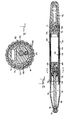
- an inflatable penile prosthetic device 10 of the unitary type is shown in Fig. It comprises an implantable device sized to be implanted within one corpus cavernosum of the penis. Normally two of such broadly tubular unitary devices of the kind shown in Fig. 1 are implanted, one in each corpus cavernosum. However, if desired a single prosthesis could be employed. While the unitary type of implant is preferred, the prosthesis of the present invention can also be of the non-unitary type wherein, for example, the fluid reservoir can be disposed separate from the other sections of the prosthesis.
- the outer layer of the device 10 is composed of a material which is physiologically inert or biocompatible.
- a material which is physiologically inert or biocompatible is silicon rubber, but any material known to be useful for artificial devices to be implanted in the body can be employed.
- the device 10 depicted in Fig. 1 includes a proximal portion 12, a medial portion 14, and a distal portion 16.
- the proximal section 12 defines a rear reservoir 18 and provides, in this embodiment, rigidity for the distal portion regardless of the amount of fluid contained therein.
- rear tip 20 has a slightly tapered external configuration.
- a rear tip extender 22 shown in Fig. 1, preferably of the type later described, may be provided to lengthen the device 10, if desired.
- the distal portion !6 shown in Fig. 1 advantageously includes a front tip 24 that is preferably substantially rigid, so as to resist buckling when in use in the erect state.
- the tip 24 is rigid in both the erect and flaccid states.
- a pump 26 shown in Fig. 2, which typically is of the manually compressible type such as, for example, described in U.S. 4,590,927.
- pump 26 is in fluid communication with reservoir 18 through reservoir outlet hole (or holes if more than one are used) 28, reservoir ring channel 30, longitudinal passageway 32, inlet ring channel 34, inlet hole 36 and inlet check valve 38.
- the pump 26 is also in fluid communication with pressurizable chamber 40 through outlet check valve 41.
- the medial portion 14 defines the aforementioned pressurizable chamber 40. This medial portion is positioned along the length of the device 10 so that it is also medially disposed along the length of the corpus cavernosum.
- Outer layer 42 of said medial portion 14 is preferably comprised of corrugated tubing typically made of a liquid impervious material such as silicone.
- longitudinal passageway 32 Concentrially defined within said outer layer 42 is longitudinal passageway 32 (which as indicated in Fig. 3, can be represented as multiple passageways or conduits 32A).
- Pressurizable chamber 40 is defined interiorly of said passageway 32, and is comprised of two layers, i.e. an inner layer (or bladder) 46 and a substantially non-distensible layer 44 which is disposed concentrically about the inner layer 46.
- the non-distensible layer 44 may take a variety of forms, but advantageously is formed from a tubular section of woven dacron material, such as a prosthestic vascular graft material.
- the inner layer 46 can also take a variety of forms, but advantageously is formed from a tubular section of a liquid impervious material such as silicone.
- deflation valve 48 Located at the end of pressurizable chamber 40 is deflation valve 48, which will be more definitively described hereinafter with reference to Fig. 4 and Fig. 5. Adjacent to the deflation valve 48 is also skirt check valve 76, as later described. These valves are in fluid communication with pressurizable chamber 40 and with each other. While in Fig. 2 both valves are shown on the proximal side of chamber 40, the position of such can be varied.
- passageway 32 is as stated longitudinally disposed along the length of device 10 between distal portion 16 and proximal portion 12 and serves to convey fluid from the reservoir 18 to the pump 26. It is in fluid isolation with respect to pressurizable chamber 40.
- passageway 32 is in reality a series of passageways defined as 32A, as shown more clearly in Fig. 3. These passageways are interconnected with each other by means of aforementioned ring channels 34 and 30.
- the corrugated configuration of outer tubing 42 and the passageways 32A is particularly advantageous in the practice of this invention, because it permits an easier stretching of the medial portion when the device 10 is bent or hinged, which as will be shown later is important to the operation of the device.
- the corrugated shape serves to assist the assumption of a flaccid mode because there is virtually no resistance to a circumferential re-shaping when the device 10 is hinged in order to assume the flaccid mode. It has also been found that because this configuration re-shapes with a minimum of force, stress upon the silicone of the outer tubing is reduced with improvement in the friction-caused wear-time of said silicone.
- the unitary prosthesis defined in Fig. 2 contains many elements which are previously known, such as are described in U.S. 4,590,927, e.g. the stiff distal section including a pump therewithin, the medial section containing a pressurizable chamber capable of being squeezed or bent, and a proximal section defining a reservoir therewithin.
- deflation valve 48 which is fully illustrated in Fig. 4, in its closed mode. This valve provides a quick and sure means (and method) for effecting a quick and sure return of the penis containing the penile implant from the erect to flaccid state.
- deflation valve 48 which operates on a pressure differential basis, includes a housing 50.
- a poppet 52 which preferably comprises a head 54 and a shaft 56.
- Poppet head 54 is typically held in sealing contact with housing 50 by means of precalibrated spring 58 and also by the fluid pressure exerted by the fluid in the front chamber 60 which is in constant fluid communication with the pressurized chamber.
- a rear chamber 62 To the rear of the poppet shaft 56 is a rear chamber 62.
- Front chamber 60 and rear chamber 62 are in fluid communication with each other through fluid resistor means 64.
- the latter provides a predetermined time-deferred resistance to fluid flow to and from front chamber 60 and rear chamber 62.
- This element 64 may be of several types known in the art, but typically is one of the kind which defines a labyrinth type fluid passage such as one formed by a plurality of axially aligned, perforated disks which are adapted to define a restrictive path for fluid flow.
- valve 48 An important feature of the valve 48 is a movable or distensible partition 66, which is preferably made in the form of a diaphragm. It is preferably spaced apart from and to the rear of poppet shaft 56. Partition 66 is designed to impact upon the poppet shaft when the pressure in rear chamber 62 is sufficiently high. If said pressure is sufficiently high, the necessary extent of which is preset and predetermined, the partition 66 will distend and impact upon the poppet shaft with sufficient force to break the sealing contact of the poppet head 54 with the housing, thereby opening the valve 48. This open mode is shown in Fig. 5, with the lines of flow indicated therein.
- Middle chamber 68 is, as shown, disposed about the poppet shaft medial to the front chamber 60 and rear chamber 62.
- Fig. 3 depicts a transverse cross-sectional view along the axis 2-2 of Fig. 2 through the deflation valve 48.
- This figure shows the relative disposition of the corrugated outer layer 42 and the multiplicity of passageways, represented by 32A, (also referred to previously as passageway 32 with respect to the medial portion 16).
- the non-distensible layer 44 referred to with respect to pressurizable section 40, which layer extends into and is fixed onto the outer surface of the housing 50 of deflation valve 48. It also extends to the external surface of the front end of the reservoir 18 and is also affixed thereto.
- Fig. 3 also shows some of the features of deflation valve 48, in cross-section, to wit: housing 50, pressure cap 74, poppet shaft 56, resistor 64 and fluid passage channel 72.
- a skirt check valve 76 can be employed to prevent spontaneous inflation of the pressurizable chamber 40 by (unintended) transfer of fluid from the reservoir 18 to the chamber 40 through the deflation valve 48.
- This valve is shown in Fig. 2, Fig. 4 and Fig. 5.
- This valve is formed of a skirt 75 assembled about a stiffener 78.
- the skirt preferably made of silicone, comprises two cylindrical parts as shown, i.e. front part 80 and rear part 82 which are combined by a conical transition 84.
- the pressure differential between pressurized chamber 40 and reservoir 18 allows fluid to stretch the walls of the rear skirt cylinder 82 thus forming a gap between stiffener 78 and the inside walls of skirt rear cylinder 82 for fluid flow to the reservoir 18.
- the compression fit between the walls of the rear skirt cylinder 82 and stiffener 78 prevents fluid flow from reservoir 18 via the skirt check valve to the pressurized chamber 40. Any pressure increase in the reservoir 18 proportionally increases the compression fit between the skirt rear cylinder and the stiffener.
- the skirt front cylinder part is glued to a reservoir ring 90.
- Fig. 6 depicts an optional snap fit rear tip extender (hereinafter to be termed "SRTE") which permits an easy and safe manner for extending the length of the prosthetic device of this invention.
- the SRTE includes a plug at one end and a receptacle at the other.
- the SRTE receptacle comprises a guide 22a, snap ring 22b, distensible cavity 22c, and a knob 22d.
- the plug comprises a sphere 22e, neck 22f, recess 22g and step 22h.
- the guide 22a directs a SRTE on to a plug 92, shown in Fig.
- the ring 22d snaps around the neck 22f, providing a holding force.
- the knob 22d nests in recess 22g and, with the walls of cavity 22c stretched round the sphere 22e prevents the SRTE from bending and twisting relative to each other or to the prosthetic device.
- This optional feature permits virtually any length adjustment (normally with 5 mm increments), and for any device diameter. There is accordingly also a predetermined holding force for the SRTE.
- the SRTE of this embodiment does not increase the diameter of the proximal end of a prosthetic device and can be put on or off as many times as required.
- the prosthetic device operates as follows: Initially a sufficient amount of fluid is loaded into the reservoir 18 and the pressurizable tubular chamber 40, in any suitable manner, such as for example, the procedure described in U.S. 4,590,927 or by using septum 94 shown in Fig. 2. The prosthesis is then implanted within the corpus cavernosum of the patient utilizing conventional surgical techniques well. known in the implantation of penile prosthetic devices. Rear tip extenders, such as the SRTE described above, can be employed to achieve a correct fit.
- the user To operate the device after implantation, the user initially compresses the manually compressible pump 26 externally of the penis. If the pump is in the distal section, it is the tip of the penis that is compressed. The compression of the manually compressible pump 26 forces any fluid contained within the pump into the pressurizable chamber 40. This is because the pressure increase within the pump 26 forces the valve 4I open allowing fluid to flow through the valve. Spring operated inlet check valve 38 remains closed because of the pressure exerted by the compression of the pump 26.
- deflation valve 48 is normally in a closed mode as shown in Fig. 4 due to the compression force of the spring 58 and, when pressurized, the pressure of the front chamber 60.
- the fluid pressure in the front chamber 60 and rear chamber 62 of the deflation valve 48 is the same as in the pressurizable chamber 40, when the device 10 is in a flaccid or erect position.
- the user initially bends the penis somewhere along the pressurizable chamber 40, up or down, to or slightly less than a predetermined minimum angle which is typically established by the manufacturer of the prosthesis.
- the angle can be set for operation at 50-60 up or down from the original plane.
- the exact angle to be utilized is within the confines of practicality and user convenience.
- the fluid pressure in the rear chamber 62 of the deflation valve will also increase and will become equal to the increased fluid pressure of the front chamber 60 and the pressurizable chamber 40. This will occur, however, after a short time delay caused by the time-deferred passage of fluid from the front chamber to the rear chamber through the fluid resistor 64.
- the time delay (which can be predetermined) required to equalize pressure in chamber 40 and chambers 60 and 62, depends on the flow configuration of fluid resistor 64, the pressure differential between the front and rear chambers shortly after the penis is bent to the deflation angle, and the compliance of the rear chamber 62, i.e. the ease with which the latter will expand under pressure.
- the user brings the penis back to the straight position abruptly.
- the "time delays" referred to are measured in seconds, e.g. on the order of 5-10 seconds.
- the fluid pressure in the pressurizable chamber 40 and the front chamber 60 almost immediately returns to the initial level (i.e. to that level before the penis was bent to the deflation angle).
- the fluid pressure of the rear chamber 62 will not return to the initial pressure as quickly, i.e. it will remain higher for some time, (measured again in seconds) because the return flow of fluid from the rear chamber 62 to the front chamber 60 is again time-deferred because of the fluid resistor 64.
- the pressure conditions which will open the deflation valve can not require that the pressure of the rear chamber of the valve be higher than that of the front chamber.
- the same, or essentially the same, pressure in the rear chamber can impact with sufficient force on the poppet to cause the valve to assume an open mode, if the area of the wall of the movable or distensible partition is sufficiently larger than the area of the poppet head. The same time deferred sequence will then still serve to shift the pressures from the front to rear chamber.
- the force exerted will be proportional to the area of the partition as well as the pressure of the rear chamber, the latter pressure need not be greater than that of the front chamber to cause the distensible or movable partition to impact upon the poppet with sufficient force to cause the latter to break sealing contact with the valve housing.
- deflation valve of this invention is depicted as being primarily applicable to implantable penile prosthetic systems, it can also be used in conjunction with any hydraulic device where sure and quick deflation is needed or is desirable.
Landscapes
- Health & Medical Sciences (AREA)
- Engineering & Computer Science (AREA)
- General Engineering & Computer Science (AREA)
- Biomedical Technology (AREA)
- Vascular Medicine (AREA)
- Cardiology (AREA)
- Oral & Maxillofacial Surgery (AREA)
- Transplantation (AREA)
- Mechanical Engineering (AREA)
- Heart & Thoracic Surgery (AREA)
- Reproductive Health (AREA)
- Life Sciences & Earth Sciences (AREA)
- Animal Behavior & Ethology (AREA)
- General Health & Medical Sciences (AREA)
- Public Health (AREA)
- Veterinary Medicine (AREA)
- Prostheses (AREA)
Applications Claiming Priority (2)
| Application Number | Priority Date | Filing Date | Title |
|---|---|---|---|
| US07/435,641 US5010882A (en) | 1989-11-13 | 1989-11-13 | Implantable penile prosthesis |
| US435641 | 1989-11-13 |
Publications (3)
| Publication Number | Publication Date |
|---|---|
| EP0428314A2 true EP0428314A2 (de) | 1991-05-22 |
| EP0428314A3 EP0428314A3 (en) | 1992-08-12 |
| EP0428314B1 EP0428314B1 (de) | 1997-01-29 |
Family
ID=23729203
Family Applications (1)
| Application Number | Title | Priority Date | Filing Date |
|---|---|---|---|
| EP90312119A Expired - Lifetime EP0428314B1 (de) | 1989-11-13 | 1990-11-06 | Implantierbare Penisprothese |
Country Status (5)
| Country | Link |
|---|---|
| US (1) | US5010882A (de) |
| EP (1) | EP0428314B1 (de) |
| JP (1) | JPH03170153A (de) |
| CA (1) | CA2029701C (de) |
| DE (2) | DE69029839T2 (de) |
Cited By (2)
| Publication number | Priority date | Publication date | Assignee | Title |
|---|---|---|---|---|
| WO2006107845A1 (en) * | 2005-04-01 | 2006-10-12 | Coloplast A/S | Adapter for penile prosthesis tip extender |
| CN102481191A (zh) * | 2009-08-27 | 2012-05-30 | 科洛普拉斯特公司 | 阴茎假体帽、组件以及植入工具 |
Families Citing this family (40)
| Publication number | Priority date | Publication date | Assignee | Title |
|---|---|---|---|---|
| US5263981A (en) * | 1992-04-24 | 1993-11-23 | American Medical Systems, Inc. | Implantable penile prosthesis |
| US6723042B2 (en) * | 2000-12-27 | 2004-04-20 | Ams Research Corporation | Penile pump with side release mechanism |
| US6730017B2 (en) * | 2000-12-27 | 2004-05-04 | Ams Research Corporation | Pressure based spontaneous inflation inhibitor with penile pump improvements |
| US20030097178A1 (en) * | 2001-10-04 | 2003-05-22 | Joseph Roberson | Length-adjustable ossicular prosthesis |
| GB0211410D0 (en) * | 2002-05-17 | 2002-06-26 | Air Prod & Chem | Intra-cylinder tubular pressure regulator |
| US6991601B2 (en) * | 2002-12-02 | 2006-01-31 | Ams Research Corporation | Implantable pump |
| US7244227B2 (en) * | 2003-03-10 | 2007-07-17 | Ams Research Corporation | Implantable penile prosthesis pump |
| US6808490B1 (en) * | 2003-04-25 | 2004-10-26 | Ams Research Corporation | Penile prosthesis with improved tubing junction |
| US7390296B2 (en) * | 2003-06-06 | 2008-06-24 | Ams Research Corporation | Inflatable penile prosthesis with volume displacement materials and devices |
| CA2540553C (en) * | 2003-10-02 | 2011-09-20 | Ams Research Corporation | Implantable penile prosthesis pump |
| EP3569197A1 (de) | 2004-12-17 | 2019-11-20 | Boston Scientific Scimed, Inc. | Implantierbare penisprothesenpumpe |
| US7946975B2 (en) | 2005-04-08 | 2011-05-24 | Ams Research Corporation | Fluid reservoir for penile implant devices |
| US8109870B2 (en) | 2006-11-10 | 2012-02-07 | Ams Research Corporation | Inflatable penile prosthesis bypass valve noise reduction |
| US8114011B2 (en) * | 2007-10-23 | 2012-02-14 | Ams Research Corporation | Corrugated inflatable penile prosthesis cylinder |
| US8911350B2 (en) | 2007-10-23 | 2014-12-16 | Ams Research Corporation | Malleable prosthesis with enhanced concealability |
| US8123674B2 (en) | 2007-11-12 | 2012-02-28 | Ams Research Corporation | Corrugated expansion-constraining sleeve for an inflatable penile prosthesis cylinder |
| US8097014B2 (en) * | 2008-09-30 | 2012-01-17 | William D. Borkon | Variable rigidity vaginal dilator and use thereof |
| US8702589B2 (en) * | 2008-12-23 | 2014-04-22 | Ams Research Corporation | System to transport components of implantable penile prostheses |
| US7985176B1 (en) | 2010-05-26 | 2011-07-26 | Coloplast A/S | Method of implanting a penile prosthesis |
| US7959556B2 (en) * | 2009-08-27 | 2011-06-14 | Coloplast A/S | Penile prosthesis cap, assembly, and implantation tool |
| US8545393B2 (en) * | 2010-02-04 | 2013-10-01 | Coloplast A/S | Inflatable penile implant |
| US8016746B2 (en) * | 2010-02-03 | 2011-09-13 | Coloplast A/S | Inflatable penile implant |
| US8241203B2 (en) * | 2010-02-12 | 2012-08-14 | Fogarty Terence M | Inflatable penile prosthesis with spool valve |
| US8636645B2 (en) | 2010-07-16 | 2014-01-28 | Coloplast A/S | Method of treating erectile dysfunction with peristaltically inflatable penile prosthetic |
| ES2614809T3 (es) * | 2010-08-25 | 2017-06-02 | Coloplast A/S | Implante de pene con punta proximal convertible y un método para implantar una prótesis de pene |
| DK201070372A (en) * | 2010-08-25 | 2012-02-26 | Coloplast As | Penile implant with convertible proximal tip |
| US7942808B1 (en) * | 2010-08-26 | 2011-05-17 | Coloplast A/S | Method of implanting a penile prosthesis |
| US9474610B2 (en) * | 2010-12-21 | 2016-10-25 | Boston Scientific Scimed, Inc. | Adjustable length rear tip extender for penile prosthesis |
| US9084678B2 (en) | 2012-01-20 | 2015-07-21 | Ams Research Corporation | Automated implantable penile prosthesis pump system |
| US8795154B1 (en) * | 2013-07-03 | 2014-08-05 | Said I. Hakky | Propulsion inflatable penile implant |
| US9554937B2 (en) | 2014-06-16 | 2017-01-31 | Coloplast A/S | Penile prosthetic pump having an inlet valve with a lockout flange |
| US9649217B2 (en) | 2014-07-08 | 2017-05-16 | Coloplast A/S | Implantable penile prosthetic lockout valve assembly |
| US9855144B2 (en) | 2015-09-09 | 2018-01-02 | Coloplast A/S | Penile prosthetic with an insertion tool contained inside an inflatable bladder |
| ES2892483T3 (es) | 2015-09-30 | 2022-02-04 | Coloplast As | Una prótesis peneana con un manguito de inserción que se puede acoplar a una vejiga hinchable |
| US9987136B2 (en) | 2016-09-09 | 2018-06-05 | Coloplast A/S | Penile prosthetic pump with an inflation assembly including a rotary valve |
| EP4233965A3 (de) | 2017-02-02 | 2023-09-20 | Coloplast A/S | Aufblasbares penisprothesensystem |
| US11285006B2 (en) | 2018-04-09 | 2022-03-29 | Boston Scientific Scimed, Inc. | Inflatable penile prosthesis with valves for increasing flow efficiency |
| EP3708125A3 (de) | 2019-03-14 | 2020-12-30 | Coloplast A/S | Extender mit hinterer spitze für penisimplantat |
| US11547566B2 (en) | 2019-08-06 | 2023-01-10 | Boston Scientific Scimed, Inc. | Inflatable penile prosthesis with guides in valve of pump assembly |
| US11819412B2 (en) | 2020-02-04 | 2023-11-21 | Coloplast A/S | Penile prostheses for treatment of erectile dysfunction |
Citations (6)
| Publication number | Priority date | Publication date | Assignee | Title |
|---|---|---|---|---|
| US3343558A (en) * | 1964-12-22 | 1967-09-26 | United Shoe Machinery Corp | Timing valves |
| US4360010A (en) * | 1980-05-15 | 1982-11-23 | Medical Engineering Corporation | Penile prosthesis |
| DE8208210U1 (de) * | 1983-04-21 | Katalinic, Dimitrije, Dr. med., 8501 Oberasbach | Eregierbare Penisprothese | |
| US4412530A (en) * | 1981-09-21 | 1983-11-01 | American Medical Systems, Inc. | Dual-mode valve pressure regulating system |
| GB2160777A (en) * | 1984-06-26 | 1986-01-02 | Bristol Myers Co | Penile implant |
| US4590927A (en) * | 1985-02-25 | 1986-05-27 | American Medical Systems, Inc. | Unitary, inflatable penile prosthesis system |
Family Cites Families (17)
| Publication number | Priority date | Publication date | Assignee | Title |
|---|---|---|---|---|
| GB584540A (de) * | ||||
| US3853122A (en) * | 1973-10-12 | 1974-12-10 | B Strauch | Method and device for achieving a penile erection |
| US3954102A (en) * | 1974-07-19 | 1976-05-04 | American Medical Systems, Inc. | Penile erection system and methods of implanting and using same |
| US4256093A (en) * | 1978-10-12 | 1981-03-17 | The United States Of America As Represented By The Administrator Of The National Aeronautics And Space Administration | Prosthetic urinary sphincter |
| US4267829A (en) * | 1979-04-11 | 1981-05-19 | American Medical Systems, Inc. | Penile prosthesis |
| US4622958A (en) * | 1984-12-12 | 1986-11-18 | Medical Engineering Corporation | Penile implant with accumulator |
| US4318396A (en) * | 1980-05-15 | 1982-03-09 | Medical Engineering Corporation | Penile prosthesis |
| US4682589A (en) * | 1980-05-15 | 1987-07-28 | Medical Engineering Corporation | Penile prosthesis |
| US4378792A (en) * | 1980-05-15 | 1983-04-05 | Medical Engineering Corporation | Penile prosthesis |
| US4353360A (en) * | 1980-10-31 | 1982-10-12 | Medical Engineering Corporation | Penile erectile system |
| US4407278A (en) * | 1981-05-15 | 1983-10-04 | American Medical Systems, Inc. | Penile prosthesis with improved fluid control |
| US4399811A (en) * | 1981-08-04 | 1983-08-23 | Medical Engineering Corporation | Implantable penile erectile system |
| US4457335A (en) * | 1981-09-24 | 1984-07-03 | Medical Engineering Corporation | Penile erectile system |
| US4369771A (en) * | 1981-09-24 | 1983-01-25 | Medical Engineering Corporation | Penile erectile system |
| US4791917A (en) * | 1981-10-22 | 1988-12-20 | Medical Engineering Corporation | Penile prosthesis |
| NL8403174A (nl) * | 1984-10-17 | 1986-05-16 | Franciscus Jacobus Maria De Vr | Implanteerbare afsluitinrichting. |
| US4773403A (en) * | 1987-08-17 | 1988-09-27 | Medical Engineering Corporation | Penile prosthesis |
-
1989
- 1989-11-13 US US07/435,641 patent/US5010882A/en not_active Expired - Lifetime
-
1990
- 1990-11-06 EP EP90312119A patent/EP0428314B1/de not_active Expired - Lifetime
- 1990-11-06 DE DE69029839T patent/DE69029839T2/de not_active Expired - Fee Related
- 1990-11-09 CA CA002029701A patent/CA2029701C/en not_active Expired - Fee Related
- 1990-11-13 JP JP2306953A patent/JPH03170153A/ja active Granted
- 1990-11-13 DE DE9015529U patent/DE9015529U1/de not_active Expired - Lifetime
Patent Citations (6)
| Publication number | Priority date | Publication date | Assignee | Title |
|---|---|---|---|---|
| DE8208210U1 (de) * | 1983-04-21 | Katalinic, Dimitrije, Dr. med., 8501 Oberasbach | Eregierbare Penisprothese | |
| US3343558A (en) * | 1964-12-22 | 1967-09-26 | United Shoe Machinery Corp | Timing valves |
| US4360010A (en) * | 1980-05-15 | 1982-11-23 | Medical Engineering Corporation | Penile prosthesis |
| US4412530A (en) * | 1981-09-21 | 1983-11-01 | American Medical Systems, Inc. | Dual-mode valve pressure regulating system |
| GB2160777A (en) * | 1984-06-26 | 1986-01-02 | Bristol Myers Co | Penile implant |
| US4590927A (en) * | 1985-02-25 | 1986-05-27 | American Medical Systems, Inc. | Unitary, inflatable penile prosthesis system |
Cited By (3)
| Publication number | Priority date | Publication date | Assignee | Title |
|---|---|---|---|---|
| WO2006107845A1 (en) * | 2005-04-01 | 2006-10-12 | Coloplast A/S | Adapter for penile prosthesis tip extender |
| US7648456B2 (en) | 2005-04-01 | 2010-01-19 | Coloplast A/S | Adapter for penile prosthesis tip extender |
| CN102481191A (zh) * | 2009-08-27 | 2012-05-30 | 科洛普拉斯特公司 | 阴茎假体帽、组件以及植入工具 |
Also Published As
| Publication number | Publication date |
|---|---|
| US5010882A (en) | 1991-04-30 |
| CA2029701A1 (en) | 1991-05-14 |
| DE69029839D1 (de) | 1997-03-13 |
| DE69029839T2 (de) | 1997-05-15 |
| CA2029701C (en) | 1994-07-26 |
| EP0428314B1 (de) | 1997-01-29 |
| JPH0575421B2 (de) | 1993-10-20 |
| JPH03170153A (ja) | 1991-07-23 |
| EP0428314A3 (en) | 1992-08-12 |
| DE9015529U1 (de) | 1991-01-31 |
Similar Documents
| Publication | Publication Date | Title |
|---|---|---|
| EP0428314B1 (de) | Implantierbare Penisprothese | |
| EP0637233B1 (de) | Implantierbare penis-prothese | |
| EP0193352B1 (de) | Aufblasbare Penisprotheseneinheit | |
| EP0065853B1 (de) | Penisprothese mit Flüssigkeitssteuerung | |
| US5141509A (en) | Penile prosthesis having means for preventing spontaneous inflation | |
| US4574792A (en) | Penile erectile system | |
| EP1670393B1 (de) | Implantierbare penisprothesenpumpe | |
| US4424807A (en) | Penile implant | |
| US4364379A (en) | Penile erectile system | |
| US5048510A (en) | Inflatable penile prosthesis with satellite reservoir | |
| US4895139A (en) | Inflatable penile prosthesis with bend release valve | |
| US7244227B2 (en) | Implantable penile prosthesis pump | |
| CA1317703C (en) | Flat coil spring penile prosthesis | |
| US20020082471A1 (en) | Pressure based spontaneous inflation inhibitor in a pump for an inflatable prosthesis | |
| JPS5924824B2 (ja) | 植え込み可能人工ペニス |
Legal Events
| Date | Code | Title | Description |
|---|---|---|---|
| PUAI | Public reference made under article 153(3) epc to a published international application that has entered the european phase |
Free format text: ORIGINAL CODE: 0009012 |
|
| 17P | Request for examination filed |
Effective date: 19901114 |
|
| AK | Designated contracting states |
Kind code of ref document: A2 Designated state(s): DE FR GB IT |
|
| PUAL | Search report despatched |
Free format text: ORIGINAL CODE: 0009013 |
|
| AK | Designated contracting states |
Kind code of ref document: A3 Designated state(s): DE FR GB IT |
|
| 17Q | First examination report despatched |
Effective date: 19940228 |
|
| GRAG | Despatch of communication of intention to grant |
Free format text: ORIGINAL CODE: EPIDOS AGRA |
|
| GRAH | Despatch of communication of intention to grant a patent |
Free format text: ORIGINAL CODE: EPIDOS IGRA |
|
| GRAH | Despatch of communication of intention to grant a patent |
Free format text: ORIGINAL CODE: EPIDOS IGRA |
|
| GRAA | (expected) grant |
Free format text: ORIGINAL CODE: 0009210 |
|
| AK | Designated contracting states |
Kind code of ref document: B1 Designated state(s): DE FR GB IT |
|
| REF | Corresponds to: |
Ref document number: 69029839 Country of ref document: DE Date of ref document: 19970313 |
|
| ITF | It: translation for a ep patent filed | ||
| ET | Fr: translation filed | ||
| PLBE | No opposition filed within time limit |
Free format text: ORIGINAL CODE: 0009261 |
|
| STAA | Information on the status of an ep patent application or granted ep patent |
Free format text: STATUS: NO OPPOSITION FILED WITHIN TIME LIMIT |
|
| 26N | No opposition filed | ||
| REG | Reference to a national code |
Ref country code: GB Ref legal event code: IF02 |
|
| PGFP | Annual fee paid to national office [announced via postgrant information from national office to epo] |
Ref country code: GB Payment date: 20051102 Year of fee payment: 16 |
|
| PGFP | Annual fee paid to national office [announced via postgrant information from national office to epo] |
Ref country code: FR Payment date: 20051117 Year of fee payment: 16 |
|
| PGFP | Annual fee paid to national office [announced via postgrant information from national office to epo] |
Ref country code: DE Payment date: 20060102 Year of fee payment: 16 |
|
| PGFP | Annual fee paid to national office [announced via postgrant information from national office to epo] |
Ref country code: IT Payment date: 20061130 Year of fee payment: 17 |
|
| PG25 | Lapsed in a contracting state [announced via postgrant information from national office to epo] |
Ref country code: DE Free format text: LAPSE BECAUSE OF NON-PAYMENT OF DUE FEES Effective date: 20070601 |
|
| GBPC | Gb: european patent ceased through non-payment of renewal fee |
Effective date: 20061106 |
|
| REG | Reference to a national code |
Ref country code: FR Ref legal event code: ST Effective date: 20070731 |
|
| PG25 | Lapsed in a contracting state [announced via postgrant information from national office to epo] |
Ref country code: GB Free format text: LAPSE BECAUSE OF NON-PAYMENT OF DUE FEES Effective date: 20061106 |
|
| PG25 | Lapsed in a contracting state [announced via postgrant information from national office to epo] |
Ref country code: FR Free format text: LAPSE BECAUSE OF NON-PAYMENT OF DUE FEES Effective date: 20061130 |
|
| PG25 | Lapsed in a contracting state [announced via postgrant information from national office to epo] |
Ref country code: IT Free format text: LAPSE BECAUSE OF NON-PAYMENT OF DUE FEES Effective date: 20071106 |