EP0427498A2 - Ceiling recess cage - Google Patents
Ceiling recess cage Download PDFInfo
- Publication number
- EP0427498A2 EP0427498A2 EP90312106A EP90312106A EP0427498A2 EP 0427498 A2 EP0427498 A2 EP 0427498A2 EP 90312106 A EP90312106 A EP 90312106A EP 90312106 A EP90312106 A EP 90312106A EP 0427498 A2 EP0427498 A2 EP 0427498A2
- Authority
- EP
- European Patent Office
- Prior art keywords
- members
- spacer device
- panel
- light fitting
- hole
- Prior art date
- Legal status (The legal status is an assumption and is not a legal conclusion. Google has not performed a legal analysis and makes no representation as to the accuracy of the status listed.)
- Granted
Links
Images


Classifications
-
- F—MECHANICAL ENGINEERING; LIGHTING; HEATING; WEAPONS; BLASTING
- F21—LIGHTING
- F21V—FUNCTIONAL FEATURES OR DETAILS OF LIGHTING DEVICES OR SYSTEMS THEREOF; STRUCTURAL COMBINATIONS OF LIGHTING DEVICES WITH OTHER ARTICLES, NOT OTHERWISE PROVIDED FOR
- F21V25/00—Safety devices structurally associated with lighting devices
-
- F—MECHANICAL ENGINEERING; LIGHTING; HEATING; WEAPONS; BLASTING
- F21—LIGHTING
- F21V—FUNCTIONAL FEATURES OR DETAILS OF LIGHTING DEVICES OR SYSTEMS THEREOF; STRUCTURAL COMBINATIONS OF LIGHTING DEVICES WITH OTHER ARTICLES, NOT OTHERWISE PROVIDED FOR
- F21V21/00—Supporting, suspending, or attaching arrangements for lighting devices; Hand grips
- F21V21/02—Wall, ceiling, or floor bases; Fixing pendants or arms to the bases
- F21V21/04—Recessed bases
-
- F—MECHANICAL ENGINEERING; LIGHTING; HEATING; WEAPONS; BLASTING
- F21—LIGHTING
- F21S—NON-PORTABLE LIGHTING DEVICES; SYSTEMS THEREOF; VEHICLE LIGHTING DEVICES SPECIALLY ADAPTED FOR VEHICLE EXTERIORS
- F21S8/00—Lighting devices intended for fixed installation
- F21S8/02—Lighting devices intended for fixed installation of recess-mounted type, e.g. downlighters
- F21S8/026—Lighting devices intended for fixed installation of recess-mounted type, e.g. downlighters intended to be recessed in a ceiling or like overhead structure, e.g. suspended ceiling
-
- F—MECHANICAL ENGINEERING; LIGHTING; HEATING; WEAPONS; BLASTING
- F21—LIGHTING
- F21V—FUNCTIONAL FEATURES OR DETAILS OF LIGHTING DEVICES OR SYSTEMS THEREOF; STRUCTURAL COMBINATIONS OF LIGHTING DEVICES WITH OTHER ARTICLES, NOT OTHERWISE PROVIDED FOR
- F21V15/00—Protecting lighting devices from damage
- F21V15/02—Cages
Abstract
Description
- This invention relates to light fittings, and is concerned in particular with recessed light fittings, that is light fittings adapted to be mounted on a ceiling panel or the like with at least a substantial part of the fitting being accommodated in the space behind the panel remote from the area to be illuminated. Recessed light fittings are in common use and have the advantage that they are largely concealed from view, which means they can be very functional in external appearance without detracting from the aesthetic appeal when correctly installed.
- The space behind a ceiling panel used to accommodate a recessed light fitting is often that space formed between the wooden joist supporting the ceiling and possibly also the floor of the room above. For reasons of safety a minimum air gap should be left between a recessed light fitting and any adjacent structure, object, superposed material, etc. in order to provide a heat insulating air gap and hence safe operating temperatures.
- Some recessed light fittings are designed to enable them to be installed from below a ceiling through a hole formed in a ceiling panel, which can be very convenient, especially when access to the space above the ceiling panel is restricted or difficult. However, such light fittings can be installed inadvertently in such positions, e.g. closely adjacent a joist, so that the minimum air gap needed to ensure safety is not provided.
- The present invention addresses the problem explained above and as a solution provides for use with a recessed light fitting a spacer device capable of insertion through a hole provided in a mounting panel to receive the light fitting, the device being arranged to expand into the space behind the mounting panel and thereby to form a cage-like structure for surrounding the light fitting to define a minimum distance between the light fitting and any adjacent surface.
- By having a cage or frame-like structure the device does not seriously impede circulation of air within the space and cooling convection currents are maintained. However, the spacing device will ensure the correct minimum spacing between the light fitting and any laterally adjacent structural member, such as a joist, or any further floor panel (or perhaps roof space insulation material in the case of a top storey ceiling) located above the ceiling panel.
- To facilitate installation and ensure its correct location the spacer device is preferably arranged to engage the edge of the hole. In this way it is easily ensured that the device is properly centered with respect to the hole and hence the light fitting.
- The device may be arranged to expand from a collapsed or folded condition in a variety of different ways. For example it may be due to the inherent resilience of elements forming the device or by provision of additional spring means. Alternatively, insertion of the light fitting itself may cause the device to expand, which can provide the additional security that the light fitting can only be fully inserted if the device has been correctly expanded.
- A full understanding of the invention will be had from consideration of the following more detailed description which is given by way of example and with reference to the accompanying drawings, in which:-
- Figure 1 is a front elevation showing a first embodiment of a spacer device according to the invention;
- Figure 2 is a side elevation of the spacer device;
- Figure 3 is a plan view of the spacer device;
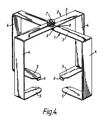
- Figure 4 is a perspective view of the spacer device;
- Figures 5A, 5B and 5C illustrate successive steps in the procedure for fitting the spacer device on a ceiling panel prior to installation of a recessed light fitting;
- Figure 6 shows in perspective a modified form of the spacer device of Figure 1;
- Figure 7 is a sketch showing the spacer device of Figure 6 during insertion through the hole in a ceiling panel;
- Figure 8 is a schematic section showing the light fitting and spacer device of Figure 6 fully installed;
- Figure 9 is an underneath perspective view showing another embodiment of a spacer device;
- Figure 10 illustrates the spacer device of Figure 9 during insertion;
- Figure 11 is a view showing the device of Figure 9 and light fitting correctly installed;
- Figure 12 shows in cross-section another form of spacer device embodying the invention;
- Figure 13 illustrates the device of Figure 12 and light fitting fully installed;
- Figure 14 is a side elevation of yet another embodiment of a spacer device;
- Figure 15 shows the device of Figure 14 mounted on a ceiling panel; and
- Figure 16 is a view corresponding to Figure 15 and including the light fitting.
- The spacer device shown in Figure 1 consists of a cage made up from two substantially
identical metal members 1, 2 each having across arm 3 from the ends of which extendparallel legs 4. The ends of the legs remote from the cross arm are connected to inturnedfeet 5 which terminate in spiked hooks 6. Thecross arms 3 are connected at their centres by apivot pin 7 which also mounts atorsion spring 8 having rectilinear end portions which are engaged with therespective members 1, 2 by having their ends hooked through holes in the cross arms. The cross arm of one member 1 has a pair of bent up lugs 9 which form stops and by abutting the edges of the cross arm of theother member 2 limit the relative pivoting movement of the members under the influence of thetorsion spring 8 to the position shown in Figs. 1-4. - When the cage is to be installed through a hole previously formed in a ceiling panel for instance, the two members are rotated against the spring bias to take up a generally planar position as shown in Figure 5A. It will be appreciated that by suitably dimensioning the
members 1, 2 they could be made to fold completely one into the other. The collapsed cage is inserted upwardly through the hole in the panel, with a rotational manipulation of the cage as depicted in Figure 5B. The cage is then released for expansion under the action of thetorsion spring 8, whereby it returns to the Figure 1 condition, and the hooks 6 are engaged with the edge of the hole by pressing their spikes into the panel material to fix the cage securely into position. The light fitting can then be mounted in the normal fashion to be received within the surrounding cage which defines a minimum air gap between the light fitting and any adjacent surface. - Whereas the cage of Figure 1 has been described as comprising only two
members 1, 2, three or even more members could be used, preferably with uniform spacing between them when the cage is correctly expanded. The device shown in Figure 6 has three such members and in this case does not comprise a spring which means the cage, after insertion through the hole in the manner shown in Figure 7, must be expanded manually to the condition shown in Figure 8, which also shows thelight fitting 10 and itsceiling ring 11 installed. Instead of being spiked, the hooks 6 engage around the edge of the panel, which is acceptable since the free ends of the hooks on the underside of the panel are covered by theceiling ring 11. - A spacer cage fabricated from
resilient strips 15 is shown in a collapsed condition in Figure 9. There are threeelongate strips 15 with upturnedend portions 16. The strips are pivoted together at their centres and have slightly different lengths to enable them to be folded to a substantially planar collapsed condition as shown in Figure 9, which is advantageous for packaging purposes. When the cage is to be installed the strips are rotated to define six uniformly spaced radial arms. The centre of the resulting spider is pushed up through the hole in the ceiling panel causing the arms to deflect downwardly and inwardly, as shown in Figure 10. Thebent end portions 16 constitute hooks which engage the edge of the hole, and in this position of the cage the arms are bowed to extend outwardly beyond the edge of the hole above the panel as may be seen in Figure 11. As in the case of the previous embodiment, thehooked ends 16 are hidden from sight by theceiling ring 11 of the light fitting 10. - The spacer device of Figure 12 is incorporated with the
ceiling ring 11 of the light fitting. Fastened to the ring are a number, e.g. 6, upwardly extendinglegs 20 which are pivoted or include integral hinges atlower end points 21. The legs includeknee portions 22 near the hinge points. The legs are arranged to extend essentially parallel to the ceiling ring axis, as depicted in Figure 11, when the device is to be introduced into the hole in a ceiling panel. In this condition theknee portions 22 protrude radially inwardly of thering 11 so that upon subsequent insertion of the light fitting this fitting engages the knee portions and cams them outwardly thereby causing the legs to turn at thehinge points 21 and assume the upwardly and outwardly inclined positions shown in Figure 13. Although not shown, thelegs 20 could be provided with inturned ends at their upper extremities to provide cage elements extending over the light fitting. - The spacer device of Figures 14 to 16 has a
central hub 24 with severalelongate spokes 25 pivoted to the hub. Each of the spokes is linked by an arm to anexpander 26 which is arranged to push out the spokes generally in similar manner to the principle used for expanding a conventional umbrella. The device is inserted through the hole in a ceiling panel in a collapsed condition. The expander is then forced up into locked engagement with thehub 24. The free ends of the spokes havehooks 28 which are engaged with the edge of the hole, after which the expansion of the cage results in the spokes being bowed to define a frame of dome-like configuration. The light fitting 10 and its ceiling ring may then be installed as shown in Figure 16. - The
spokes 25 may include hingedsegments 29 adjacent the hooks so that the segments extend radially outwardly from the edge of the hole above the panel. - It will be understood that spacer devices embodying the invention can also take other forms besides those specifically described without departing from the fundamental inventive concept of providing a frame structure to ensure a recess of predetermined minimum dimensions to receive a recessed light fitting.
Claims (12)
Applications Claiming Priority (2)
| Application Number | Priority Date | Filing Date | Title |
|---|---|---|---|
| GB8925503 | 1989-11-10 | ||
| GB8925503A GB2237867B (en) | 1989-11-10 | 1989-11-10 | Light fittings |
Publications (3)
| Publication Number | Publication Date |
|---|---|
| EP0427498A2 true EP0427498A2 (en) | 1991-05-15 |
| EP0427498A3 EP0427498A3 (en) | 1991-11-06 |
| EP0427498B1 EP0427498B1 (en) | 1995-05-17 |
Family
ID=10666129
Family Applications (1)
| Application Number | Title | Priority Date | Filing Date |
|---|---|---|---|
| EP90312106A Expired - Lifetime EP0427498B1 (en) | 1989-11-10 | 1990-11-05 | Ceiling recess cage |
Country Status (3)
| Country | Link |
|---|---|
| EP (1) | EP0427498B1 (en) |
| DE (1) | DE69019468T2 (en) |
| GB (1) | GB2237867B (en) |
Cited By (10)
| Publication number | Priority date | Publication date | Assignee | Title |
|---|---|---|---|---|
| DE19755996C2 (en) * | 1997-12-17 | 2003-07-10 | Edwin Weindl | Installation device for a ceiling lamp in a false ceiling |
| WO2012080758A3 (en) * | 2010-12-17 | 2012-08-09 | Aurora Limited | Improved downlights |
| EP2541125A1 (en) * | 2011-06-30 | 2013-01-02 | Hellermanntyton | Ceiling lamp capping |
| EP2546564A1 (en) * | 2011-07-15 | 2013-01-16 | Hellermanntyton | Capping device of a ceiling lamp |
| FR2986055A1 (en) * | 2012-01-24 | 2013-07-26 | Hellermanntyton | CEILING LAMP STAMPING |
| EP2592335B1 (en) * | 2011-11-08 | 2014-09-17 | Ram Chevilles Et Fixations | Heat dissipating cage |
| EP2787274A1 (en) * | 2013-04-03 | 2014-10-08 | Ram Chevilles Et Fixations | Sealed protective cage |
| EP2860445A1 (en) * | 2013-09-24 | 2015-04-15 | Moulages Plastiques du Midi | Covering device for a spot-type lighting fixture |
| DE102014101337A1 (en) * | 2013-11-13 | 2015-05-13 | Siteco Beleuchtungstechnik Gmbh | Insert ring for rotatable recessed luminaire |
| FR3081042A1 (en) * | 2018-05-09 | 2019-11-15 | Moulages Plastiques Du Midi | INSULATING ENHANCEMENT DEVICE FOR PROTECTING A LIGHTING SYSTEM |
Families Citing this family (6)
| Publication number | Priority date | Publication date | Assignee | Title |
|---|---|---|---|---|
| US6116749A (en) | 1998-06-03 | 2000-09-12 | Spaulding Lighting, Inc. | Canopy luminaire assembly |
| GB2354816B (en) * | 1999-10-02 | 2003-08-20 | John Sinnott | Guard means for a lamp assembly |
| DE102013112303B4 (en) | 2013-11-08 | 2022-09-22 | Kaiser Gmbh & Co. Kg | spacer device |
| DE202014105845U1 (en) | 2014-12-04 | 2016-03-07 | Kaiser Gmbh & Co Kg | Hollow ceiling with fire enclosure and fire enclosure |
| GB2536280B (en) * | 2015-03-13 | 2017-03-29 | Astro Lighting Ltd | A spacer |
| GB201800066D0 (en) * | 2018-01-03 | 2018-02-14 | Scolmore Int Ltd | Insulation Support |
Citations (2)
| Publication number | Priority date | Publication date | Assignee | Title |
|---|---|---|---|---|
| BE684033A (en) * | 1965-07-21 | 1966-12-16 | ||
| DE8526751U1 (en) * | 1985-09-19 | 1985-10-31 | Brocke, Hartmut, 5828 Ennepetal | Recessed light |
-
1989
- 1989-11-10 GB GB8925503A patent/GB2237867B/en not_active Expired - Lifetime
-
1990
- 1990-11-05 EP EP90312106A patent/EP0427498B1/en not_active Expired - Lifetime
- 1990-11-05 DE DE69019468T patent/DE69019468T2/en not_active Expired - Fee Related
Patent Citations (2)
| Publication number | Priority date | Publication date | Assignee | Title |
|---|---|---|---|---|
| BE684033A (en) * | 1965-07-21 | 1966-12-16 | ||
| DE8526751U1 (en) * | 1985-09-19 | 1985-10-31 | Brocke, Hartmut, 5828 Ennepetal | Recessed light |
Cited By (15)
| Publication number | Priority date | Publication date | Assignee | Title |
|---|---|---|---|---|
| DE19755996C2 (en) * | 1997-12-17 | 2003-07-10 | Edwin Weindl | Installation device for a ceiling lamp in a false ceiling |
| WO2012080758A3 (en) * | 2010-12-17 | 2012-08-09 | Aurora Limited | Improved downlights |
| EP2541125A1 (en) * | 2011-06-30 | 2013-01-02 | Hellermanntyton | Ceiling lamp capping |
| EP2546564A1 (en) * | 2011-07-15 | 2013-01-16 | Hellermanntyton | Capping device of a ceiling lamp |
| EP2592335B1 (en) * | 2011-11-08 | 2014-09-17 | Ram Chevilles Et Fixations | Heat dissipating cage |
| EP2620701A1 (en) * | 2012-01-24 | 2013-07-31 | Hellermanntyton | Ceiling lamp capping |
| FR2986055A1 (en) * | 2012-01-24 | 2013-07-26 | Hellermanntyton | CEILING LAMP STAMPING |
| EP2787274A1 (en) * | 2013-04-03 | 2014-10-08 | Ram Chevilles Et Fixations | Sealed protective cage |
| FR3004236A1 (en) * | 2013-04-03 | 2014-10-10 | Ram Chevilles Et Fixations | THERMAL CAGE SEALED |
| EP2860445A1 (en) * | 2013-09-24 | 2015-04-15 | Moulages Plastiques du Midi | Covering device for a spot-type lighting fixture |
| DE102014101337A1 (en) * | 2013-11-13 | 2015-05-13 | Siteco Beleuchtungstechnik Gmbh | Insert ring for rotatable recessed luminaire |
| DE102014101337B4 (en) * | 2013-11-13 | 2015-06-18 | Siteco Beleuchtungstechnik Gmbh | Insert ring for rotatable recessed luminaire |
| AT515009A3 (en) * | 2013-11-13 | 2016-01-15 | Siteco Beleuchtungstech Gmbh | Insert ring for rotatable recessed luminaire |
| AT515009B1 (en) * | 2013-11-13 | 2016-04-15 | Siteco Beleuchtungstech Gmbh | Insert ring for rotatable recessed luminaire |
| FR3081042A1 (en) * | 2018-05-09 | 2019-11-15 | Moulages Plastiques Du Midi | INSULATING ENHANCEMENT DEVICE FOR PROTECTING A LIGHTING SYSTEM |
Also Published As
| Publication number | Publication date |
|---|---|
| EP0427498A3 (en) | 1991-11-06 |
| EP0427498B1 (en) | 1995-05-17 |
| DE69019468T2 (en) | 1996-01-04 |
| GB2237867B (en) | 1992-09-02 |
| GB2237867A (en) | 1991-05-15 |
| DE69019468D1 (en) | 1995-06-22 |
| GB8925503D0 (en) | 1989-12-28 |
Similar Documents
| Publication | Publication Date | Title |
|---|---|---|
| EP0427498B1 (en) | Ceiling recess cage | |
| US6030102A (en) | Trim retention system for recessed lighting fixture | |
| CA2054352C (en) | Lighting fixture assembly | |
| US4764008A (en) | Surveillance housing assembly | |
| CA2202599C (en) | Trim support for recessed lighting fixture | |
| CA1157836A (en) | Lighting fixture with uniform mounting frame for new installations | |
| US5957572A (en) | Remodeler light fixture support structure and method | |
| CA2147236A1 (en) | Hanger | |
| CA2301367C (en) | Outdoor light mounting bracket | |
| US6378964B2 (en) | Rotary stepped storage and display device and method | |
| KR200413111Y1 (en) | Fixing apparatus for ceiling insert illuminator | |
| KR100719082B1 (en) | Fixing apparatus for ceiling insert illuminator | |
| US6612531B2 (en) | Structure two-level suspended lamp frame | |
| US8444302B1 (en) | Pivoting recessed light fixture | |
| US3415018A (en) | Grid supported ceiling lighting fixture | |
| RU2005128486A (en) | SOCKET SOCKET WITH SAFETY TAPE AND MULTIFUNCTIONAL FRAME | |
| US4848312A (en) | Safety accessory for a field range | |
| JPH0313929Y2 (en) | ||
| EP1741849A1 (en) | Functional ceiling system | |
| KR960006893Y1 (en) | Assembling boxing ring | |
| CA2345358A1 (en) | Ceiling fan with easy installation features | |
| KR101686652B1 (en) | Air conditioning device diffuser | |
| KR200146731Y1 (en) | The support for the garland of flowers | |
| JP3020297U (en) | Step | |
| JPS6335755Y2 (en) |
Legal Events
| Date | Code | Title | Description |
|---|---|---|---|
| PUAI | Public reference made under article 153(3) epc to a published international application that has entered the european phase |
Free format text: ORIGINAL CODE: 0009012 |
|
| AK | Designated contracting states |
Kind code of ref document: A2 Designated state(s): BE CH DE FR GB IT LI NL |
|
| PUAL | Search report despatched |
Free format text: ORIGINAL CODE: 0009013 |
|
| AK | Designated contracting states |
Kind code of ref document: A3 Designated state(s): BE CH DE FR GB IT LI NL |
|
| 17P | Request for examination filed |
Effective date: 19920501 |
|
| RAP1 | Party data changed (applicant data changed or rights of an application transferred) |
Owner name: CONCORD LIGHTING LIMITED |
|
| 17Q | First examination report despatched |
Effective date: 19940325 |
|
| GRAA | (expected) grant |
Free format text: ORIGINAL CODE: 0009210 |
|
| STAA | Information on the status of an ep patent application or granted ep patent |
Free format text: STATUS: THE PATENT HAS BEEN GRANTED |
|
| AK | Designated contracting states |
Kind code of ref document: B1 Designated state(s): BE CH DE FR GB IT LI NL |
|
| PG25 | Lapsed in a contracting state [announced via postgrant information from national office to epo] |
Ref country code: LI Effective date: 19950517 Ref country code: CH Effective date: 19950517 Ref country code: BE Effective date: 19950517 |
|
| ITF | It: translation for a ep patent filed |
Owner name: JACOBACCI & PERANI S.P.A. |
|
| REF | Corresponds to: |
Ref document number: 69019468 Country of ref document: DE Date of ref document: 19950622 |
|
| ET | Fr: translation filed | ||
| REG | Reference to a national code |
Ref country code: CH Ref legal event code: PL |
|
| PLBE | No opposition filed within time limit |
Free format text: ORIGINAL CODE: 0009261 |
|
| 26N | No opposition filed | ||
| PGFP | Annual fee paid to national office [announced via postgrant information from national office to epo] |
Ref country code: GB Payment date: 19971027 Year of fee payment: 8 |
|
| PGFP | Annual fee paid to national office [announced via postgrant information from national office to epo] |
Ref country code: FR Payment date: 19971112 Year of fee payment: 8 |
|
| PGFP | Annual fee paid to national office [announced via postgrant information from national office to epo] |
Ref country code: DE Payment date: 19971114 Year of fee payment: 8 |
|
| PGFP | Annual fee paid to national office [announced via postgrant information from national office to epo] |
Ref country code: NL Payment date: 19971130 Year of fee payment: 8 |
|
| PG25 | Lapsed in a contracting state [announced via postgrant information from national office to epo] |
Ref country code: GB Free format text: LAPSE BECAUSE OF NON-PAYMENT OF DUE FEES Effective date: 19981105 |
|
| PG25 | Lapsed in a contracting state [announced via postgrant information from national office to epo] |
Ref country code: NL Free format text: LAPSE BECAUSE OF NON-PAYMENT OF DUE FEES Effective date: 19990601 |
|
| GBPC | Gb: european patent ceased through non-payment of renewal fee |
Effective date: 19981105 |
|
| PG25 | Lapsed in a contracting state [announced via postgrant information from national office to epo] |
Ref country code: FR Free format text: LAPSE BECAUSE OF NON-PAYMENT OF DUE FEES Effective date: 19990730 |
|
| NLV4 | Nl: lapsed or anulled due to non-payment of the annual fee |
Effective date: 19990601 |
|
| REG | Reference to a national code |
Ref country code: FR Ref legal event code: ST |
|
| PG25 | Lapsed in a contracting state [announced via postgrant information from national office to epo] |
Ref country code: DE Free format text: LAPSE BECAUSE OF NON-PAYMENT OF DUE FEES Effective date: 19990901 |
|
| PG25 | Lapsed in a contracting state [announced via postgrant information from national office to epo] |
Ref country code: IT Free format text: LAPSE BECAUSE OF NON-PAYMENT OF DUE FEES;WARNING: LAPSES OF ITALIAN PATENTS WITH EFFECTIVE DATE BEFORE 2007 MAY HAVE OCCURRED AT ANY TIME BEFORE 2007. THE CORRECT EFFECTIVE DATE MAY BE DIFFERENT FROM THE ONE RECORDED. Effective date: 20051105 |