EP0425307B1 - Verfahren und Vorrichtung für das Beschichten von Behältern mit kontrolliertem Profil - Google Patents
Verfahren und Vorrichtung für das Beschichten von Behältern mit kontrolliertem Profil Download PDFInfo
- Publication number
- EP0425307B1 EP0425307B1 EP90311766A EP90311766A EP0425307B1 EP 0425307 B1 EP0425307 B1 EP 0425307B1 EP 90311766 A EP90311766 A EP 90311766A EP 90311766 A EP90311766 A EP 90311766A EP 0425307 B1 EP0425307 B1 EP 0425307B1
- Authority
- EP
- European Patent Office
- Prior art keywords
- coating
- stream
- tunnel
- input opening
- conveyor path
- Prior art date
- Legal status (The legal status is an assumption and is not a legal conclusion. Google has not performed a legal analysis and makes no representation as to the accuracy of the status listed.)
- Expired - Lifetime
Links
- 238000000576 coating method Methods 0.000 title claims abstract description 172
- 239000011248 coating agent Substances 0.000 title claims abstract description 165
- 238000000034 method Methods 0.000 title claims description 43
- 239000011521 glass Substances 0.000 claims abstract description 36
- 239000000126 substance Substances 0.000 claims abstract description 7
- 238000007664 blowing Methods 0.000 claims description 16
- 150000001875 compounds Chemical class 0.000 claims description 6
- 230000003993 interaction Effects 0.000 claims description 6
- 238000010008 shearing Methods 0.000 claims description 4
- YMLFYGFCXGNERH-UHFFFAOYSA-K butyltin trichloride Chemical compound CCCC[Sn](Cl)(Cl)Cl YMLFYGFCXGNERH-UHFFFAOYSA-K 0.000 claims description 2
- 230000003134 recirculating effect Effects 0.000 claims 2
- 239000000463 material Substances 0.000 abstract description 12
- 239000000376 reactant Substances 0.000 abstract description 4
- 230000008569 process Effects 0.000 description 34
- 239000002243 precursor Substances 0.000 description 17
- 239000003570 air Substances 0.000 description 9
- 239000012530 fluid Substances 0.000 description 8
- 238000011282 treatment Methods 0.000 description 5
- 235000008452 baby food Nutrition 0.000 description 4
- 238000006243 chemical reaction Methods 0.000 description 4
- 229910052751 metal Inorganic materials 0.000 description 4
- 239000002184 metal Substances 0.000 description 4
- 229910044991 metal oxide Inorganic materials 0.000 description 4
- 150000004706 metal oxides Chemical class 0.000 description 4
- 210000003739 neck Anatomy 0.000 description 4
- 230000009471 action Effects 0.000 description 3
- 238000005229 chemical vapour deposition Methods 0.000 description 3
- 230000000295 complement effect Effects 0.000 description 3
- 230000000694 effects Effects 0.000 description 3
- 230000006872 improvement Effects 0.000 description 3
- 239000000314 lubricant Substances 0.000 description 3
- 238000000926 separation method Methods 0.000 description 3
- XOLBLPGZBRYERU-UHFFFAOYSA-N tin dioxide Chemical compound O=[Sn]=O XOLBLPGZBRYERU-UHFFFAOYSA-N 0.000 description 3
- 239000006227 byproduct Substances 0.000 description 2
- 230000007423 decrease Effects 0.000 description 2
- 238000000151 deposition Methods 0.000 description 2
- 238000004519 manufacturing process Methods 0.000 description 2
- 229910001887 tin oxide Inorganic materials 0.000 description 2
- VXUYXOFXAQZZMF-UHFFFAOYSA-N titanium(IV) isopropoxide Chemical compound CC(C)O[Ti](OC(C)C)(OC(C)C)OC(C)C VXUYXOFXAQZZMF-UHFFFAOYSA-N 0.000 description 2
- 241000272173 Calidris Species 0.000 description 1
- ATJFFYVFTNAWJD-UHFFFAOYSA-N Tin Chemical compound [Sn] ATJFFYVFTNAWJD-UHFFFAOYSA-N 0.000 description 1
- 229910021627 Tin(IV) chloride Inorganic materials 0.000 description 1
- GWEVSGVZZGPLCZ-UHFFFAOYSA-N Titan oxide Chemical compound O=[Ti]=O GWEVSGVZZGPLCZ-UHFFFAOYSA-N 0.000 description 1
- RTAQQCXQSZGOHL-UHFFFAOYSA-N Titanium Chemical compound [Ti] RTAQQCXQSZGOHL-UHFFFAOYSA-N 0.000 description 1
- 238000005299 abrasion Methods 0.000 description 1
- 230000002411 adverse Effects 0.000 description 1
- 239000012080 ambient air Substances 0.000 description 1
- 238000000137 annealing Methods 0.000 description 1
- 230000015572 biosynthetic process Effects 0.000 description 1
- 239000008294 cold cream Substances 0.000 description 1
- 238000010276 construction Methods 0.000 description 1
- 239000002537 cosmetic Substances 0.000 description 1
- 235000014113 dietary fatty acids Nutrition 0.000 description 1
- 238000009792 diffusion process Methods 0.000 description 1
- 238000006073 displacement reaction Methods 0.000 description 1
- 230000007717 exclusion Effects 0.000 description 1
- 229930195729 fatty acid Natural products 0.000 description 1
- 239000000194 fatty acid Substances 0.000 description 1
- 150000004665 fatty acids Chemical class 0.000 description 1
- 239000005002 finish coating Substances 0.000 description 1
- 235000013305 food Nutrition 0.000 description 1
- 229910000078 germane Inorganic materials 0.000 description 1
- 230000001939 inductive effect Effects 0.000 description 1
- 235000015110 jellies Nutrition 0.000 description 1
- 239000008274 jelly Substances 0.000 description 1
- 239000000203 mixture Substances 0.000 description 1
- 239000006060 molten glass Substances 0.000 description 1
- 230000001590 oxidative effect Effects 0.000 description 1
- 235000021400 peanut butter Nutrition 0.000 description 1
- 239000000047 product Substances 0.000 description 1
- 239000011253 protective coating Substances 0.000 description 1
- 238000004064 recycling Methods 0.000 description 1
- 230000004044 response Effects 0.000 description 1
- 235000014438 salad dressings Nutrition 0.000 description 1
- 241000894007 species Species 0.000 description 1
- 238000005118 spray pyrolysis Methods 0.000 description 1
- 238000005507 spraying Methods 0.000 description 1
- 239000000758 substrate Substances 0.000 description 1
- 230000009974 thixotropic effect Effects 0.000 description 1
- 150000003606 tin compounds Chemical class 0.000 description 1
- HPGGPRDJHPYFRM-UHFFFAOYSA-J tin(iv) chloride Chemical compound Cl[Sn](Cl)(Cl)Cl HPGGPRDJHPYFRM-UHFFFAOYSA-J 0.000 description 1
- 239000010936 titanium Substances 0.000 description 1
- 229910052719 titanium Inorganic materials 0.000 description 1
- 150000003609 titanium compounds Chemical class 0.000 description 1
- XJDNKRIXUMDJCW-UHFFFAOYSA-J titanium tetrachloride Chemical compound Cl[Ti](Cl)(Cl)Cl XJDNKRIXUMDJCW-UHFFFAOYSA-J 0.000 description 1
- 238000011144 upstream manufacturing Methods 0.000 description 1
Images

Classifications
-
- C—CHEMISTRY; METALLURGY
- C03—GLASS; MINERAL OR SLAG WOOL
- C03C—CHEMICAL COMPOSITION OF GLASSES, GLAZES OR VITREOUS ENAMELS; SURFACE TREATMENT OF GLASS; SURFACE TREATMENT OF FIBRES OR FILAMENTS MADE FROM GLASS, MINERALS OR SLAGS; JOINING GLASS TO GLASS OR OTHER MATERIALS
- C03C17/00—Surface treatment of glass, not in the form of fibres or filaments, by coating
- C03C17/001—General methods for coating; Devices therefor
- C03C17/003—General methods for coating; Devices therefor for hollow ware, e.g. containers
- C03C17/005—Coating the outside
Definitions
- This invention is in the field of methods and apparatus for the application of coatings to containers.
- the present invention relates to methods and devices for the application of coatings of varying thicknesses to glass bottles, jars and the like, particularly where the distance between a closure region and a shoulder of the container is small.
- Such treatments include, e.g., spraying with lubricant such as a wax or fatty acid, and applying reactive coatings by chemical-vapor-deposition (CVD) or spray pyrolysis methods.
- CVD chemical-vapor-deposition
- Treatment by CVD typically can involve propelling a vapor of metal-containing species onto the hot glass-container surface to produce a thin layer of metal oxide, typically stannic or titanic oxide.
- This metal-oxide layer anchors the waxy lubricant which is added after annealing. Without the metal-oxide layer, such waxy lubricants do not adhere well to glass under the conditions encountered in a wet filling line.
- the disclosure describes a coating hood for applying a uniform protective coating to a glass container as the container a transported by material-handling means, generally a conveyor belt, after its formation from molten glass.
- the described coating hood comprises a pair of side walls with a coating jet in at least one of the walls, and an exhaust system to remove the process stream from the coating zone.
- the open end has a structure to accommodate a closure such as a cap with screw threads or a gasketed lid for a friction or vacuum seal.
- This portion of the container is referred to in the art as the "finish" of the bottle or jar.
- the film deposited onto the glass surface is measured in arbitrary coating thickness units (CTU), the unit thickness being about 2.5 Angstroms ( ⁇ ); tin-oxide coatings of from about 30 to 40 CTU's, or about 75 to 100 ⁇ , may be required for the body of the container, while acceptable coating on the finish may be one-half or even one-tenth of this amount, depending upon the ware and its intended use. While manufacturers of baby food state a preference for finish coating of less than half the shoulder coating, proximity of finish to shoulder has heretofore made the desired separation difficult or impossible to achieve under the teachings of the prior art.
- CTU coating thickness units
- ⁇ tin-oxide coatings of from about 30 to 40 CTU's, or about 75 to 100 ⁇
- US-A-4 668 268 is only marginal for applications such as food and cosmetic bottles and jars having very short or non-extent necks.
- the latter group comprises, e.g., jam, jelly and cold-cream jars, and containers for baby foods, peanut butter, thixotropic salad dressings, and the like.
- Displacement can originate, e.g. in the shearing interaction between adjacent coating streams traversing the hood in opposite directions; in the turbulence caused by the ware as it crosses the coating streams; in the strong convection currents caused by hot ware moving through a coating stream that is typically hundreds of degrees cooler than the ware; and in the induced draft caused by the finish-protection stream.
- This invention provides apparatus for applying a coating to glass containers, e.g. baby food jars and other substantially short-necked ware, comprising a tunnel having a roof and sides, a conveyor whereby the glass containers are conveyed through the tunnel along a conveyor path, and at least first and second coating stages along the conveyor path to blow respective first and second coating gas streams, across the conveyor path in opposite directions;
- a coating e.g. baby food jars and other substantially short-necked ware
- This invention embraces provision of apparatus for the coating of glass containers having a minimal neck region, the apparatus comprising a coating hood with a high-pressure portion and a juxtaposed low-pressure portion, with a center section for the introduction of air which is free of coating precursor, and traveling in essentially the same direction as the coating stream.
- the apparatus includes means for process-stream transfer and coating-precursor makeup.
- the invention further includes the article made by the apparatus, and coating methods using same.
- a preferred embodiment of the present apparatus enables the application of glass-treating material to a glass container having a minimal separation between the body of the container and the top portion, the apparatus comprising coating-supply means and exhaust or recirculation means, the coating-supply means having a plurality of coating-precursor slots on one side of the apparatus and a cooperating low-pressure area on the opposite side, the apparatus having a process-stream-directing means juxtaposed above the container and intermediate the two sides of the apparatus.
- the coating-process stream maintains a substantially horizontal direction until it passes the ware.
- Means are provided for transfer of the process stream from the low-pressure to the high-pressure side of the device, and for makeup as necessary of the coating-precursor material.
- the apparatus differs from the prior art, described above, in having at least one coating-precursor supply section in cooperation with at least one opposing exhaust section, and stream-deflection means consisting of a center section providing a stream of vapor-free air moving above and in the same direction as the coating stream.
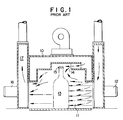
- FIG. 1 is a sectional elevation of the apparatus disclosed by Lindner et al., in U.S. 4,668,268.
- the Lindner et al. patent shows apparatus for the coating of a container, generally of glass, whereby a process stream 11 under pressure from blower 12 impinges upon bottle 13.
- Deflection stream 14 flowing substantially in the same direction as stream 11 , is intended to keep stream 11 from depositing an undesirably thick coating of material on the finish 15 of bottle 13 .
- Recirculation blower 16 maintains a low pressure within plenum 17 to cause process stream 11 to move onto and around bottle 13 , thereby causing the coating precursor to react with the hot surface of the glass substrate.
- Other portions of the apparatus not germane to this invention are not further described here. As usually preferred, it is substantially isolated from ambient atmosphere.
- process stream 11 is generally a mixture of glass-coating precursors such as, e.g., an organotin compound In air or a titanium compound.
- organotin compounds also useful with apparatus of the present invention, include those which are capable of reaction with air or other process stream oxidizing moiety to form a metal oxide, and comprise, e.g., organotin compounds generally, monobutyltin trichloride, tin tetrachloride, titanium tetrachloride and tetraisopropyl titanate.
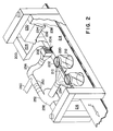
- FIG. 2 depicts an embodiment of this invention, the apparatus being shown partially in phantom.
- Coating hood 200 differs from the prior art by minimizing the shearing interaction of adjacent coating and finish-protection streams. This improvement decreases the movement of coating precursor into the finish region by induced drafts and turbulent currents.
- vertical slots 202 in wall 204 provide a substantially laminar process-stream flow 206 across tunnel 216 .
- Wall 204 holds horizontal slot 210 , justaposed opposite vertical slot s 202 .
- a second, similar set of process stream input slots 202 and out-take slot 210 is provided on the opposite side of the conveyor, but with the out-take upstream of the input so as to complement the set-up shown in Fig. 2. This gives two longitudinally-spaced process paths, reducing shearing turbulence therebetween while achieving good coverage.
- process stream 206 impinges upon container 212 carried on conveyor 214 through tunnel 216 in the direction indicated as C in the drawing; container 212 with body portion 220 and finish region 222 may be at a temperature of about 250 to 315 degrees Centigrade, but in any event at a surface temperature sufficient to cause the reaction at that surface of the coating precursor in the process stream with ambient air in order to provide the desired coating, generally an oxide of tin or titanium.
- the present apparatus maintains a smooth, laminar, flow of the process stream 206 over the surface of container 212 , avoiding the turbulence encountered in the prior art.
- the process stream is removed through slots 210 and recirculated, as shown in Figures 2, 3 and 4.
- center section 230 provides even better control over the process stream in the finish region 222 of container 212 .
- Channel or duct portion 232 is adjusted to permit close clearance of container 212 , and the size of the channel is chosen to provide clearance between channel 232 and finish region 222 of container 212 with a tolerance of from about 2 to about 5 mm (these values are merely exemplary).
- a fluid 236 not containing coating precursor is urged through slot 239 in a manner such that the direction and velocity of flow does not create turbulence, nor substantially interact, with process stream 206 .
- fluid 236 leaves the treatment region through exhaust channel 234 while the effluent of process stream 206 is drawn off through slots 210 .
- the fluid stream 236 is introduced at approximately the same velocity as the process stream 206, in order to achieve the reduced turbulence.
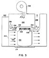
- a further feature, as seen in Fig. 3, is for the input opening 239 of flow 236, to open directly adjacent the projection across the tunnel of process stream input opening 202.
- process-stream flow 206 may be at least partially exhausted or gently deflected downward and drawn into low-pressure slot 210 ; see further the discussion hereinbelow with reference to Figure 6.
- process stream 206 there is minimal interaction between process stream 206 and fluid 236 until they are no longer in proximity to the finish region 222 of bottle or jar 212 which so is substantially uncoated by the action of the precursor materials carried in process stream 206 .
- the action of the fluid 236 generally air, is to preclude reaction on finish region 222 of coating-precursor chemicals carried In process stream 206 .
- precise coating of container 212 is achieved, depositing sufficient coating on body 220 while minimizing the thickness of coating on finish region 222 .
- Figure 3 shows a greater detail of center section 230 disposed in tunnel 216 .
- non-coating fluid stream 236 flows from openings 239 and is directed by the conformation of curvilinear portion 234 as shown by arrows 308 .
- the conformation of the curvilinear portion 234 of channel 232 is preferably complementary with the finish region of the container. After non-coating stream 236 has passed across finish region 222 of container 212 , it is given a stint vertical component by the conformation 234 of center section 230 ; the major portion of stream 236 is then removed through air exhaust 238 which directly opposes input opening 239.
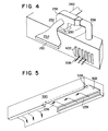
- FIG. 4 shows wall 204 of the apparatus in greater detail.
- Recirculation loop 250 comprises a conduit 252 drawing process-stream materials and spent reactants through duct 254 and in turn recycling them by means of duct 256 back through slots 202 .
- Blower or other fluid-motive device 258 serves as the means to move the process and reactant stream;
- conduit arm 260 provides a make-up port for the introduction of reactants or stream adjustment as may be required to meet process conditions such as line speed, temperature fluctuation, coating-thickness specifications and the like.
- vertical slots 202 provide a laminar flow of the process stream; the height 402 of slots 202 is conveniently, although not necessarily, chosen to be identical with the height of the body of the container 212 shown in Figure 2, and less than the height of the finish region of that container. In this fashion, process stream 206 impinges on the body 220 , but not on the finish region 222 , of container 212 .
- the function of horizontal slots 210 is to remove the spent process stream and reaction by-products without inducing turbulence.
- Figures 5 and 6 illustrate the function and construction of another embodiment of this invention
- center section 530 is shown in perspective.
- Finish-protection stream 236 exits through slot 239 , traverses surface 502 , and follows conformation 534 , the effect of which is to provide a downward vector to maintain finish 222 of container 212 essentially free of coating. From a review of this disclosure, those skilled in the art will recognize that the lower portion of finish-protection stream 236 will become enriched with coating-precursor stream 206 by diffusion, convection, and impingement of coating-precursor stream 206 upon container 212.
- Figure 6 shows center section 530 in coating hood 200.
- center section 530 of this embodiment is disposed in tunnel 216 .
- non-coating fluid stream 236 flows from openings 239 and is directed by the conformation of curvilinear portion 534 as shown by arrows 608 .
- the conformation of the portion 534 of channel 632 is preferably complementary with the finish region of the container.
- non-coating stream 239 has passed across finish region 222 of container 212 , it is given a vertical component by the conformation of the curvilinear portion 534 of center section 530.
- the mixed coating-precursor and finish-protection streams 640 are then recirculated for further application to more containers 212 after the manner noted above in connection with Figure 2.
Landscapes
- Chemical & Material Sciences (AREA)
- Materials Engineering (AREA)
- Engineering & Computer Science (AREA)
- Chemical Kinetics & Catalysis (AREA)
- General Chemical & Material Sciences (AREA)
- Geochemistry & Mineralogy (AREA)
- Life Sciences & Earth Sciences (AREA)
- Organic Chemistry (AREA)
- Surface Treatment Of Glass (AREA)
- Details Of Rigid Or Semi-Rigid Containers (AREA)
- Application Of Or Painting With Fluid Materials (AREA)
- Electrostatic Spraying Apparatus (AREA)
- Chemical Vapour Deposition (AREA)
- Coating Apparatus (AREA)
- Spray Control Apparatus (AREA)
Claims (17)
- Einrichtung zum Aufbringen einer Beschichtung auf Glasbehälter, umfassend einen Tunnel (216), der ein Dach (230) und Seiten (204) hat, einen Förderer (214), wodurch die Glasbehälter (212) längs eines Förderwegs durch den Tunnel gefördert werden, und wenigstens eine erste und zweite Beschichtungsstufe längs des Förderwegs zum Blasen eines jeweiligen ersten und zweiten Beschichtungsgasstroms (206) quer über den Förderweg in entgegengesetzten Richtungen;(a) die erste Beschichtungsstufe hat(i) eine erste Beschichtungsstromeinlaßöffnung (202) in einer ersten Seite des Tunnels gegenüber einer ersten Beschichtungsstromauslaßöffnung (210) in der zweiten Seite des Tunnels;(ii) Mittel (252, 256, 258) zum Blasen des ersten Beschichtungsgasstroms (206) durch die erste Beschichtungsstromeinlaßöffnung (202) auf den Förderweg und Auslassen bzw. Absaugen desselben durch die erste Beschichtungsstromauslaßöffnung (210);(iii) eine erste Nichtbeschichtungsstromeinlaßöffnung (239) oberhalb der ersten Beschichtungsstromeinlaßöffnung (202), und(iv) Mittel (302) zum Blasen eines ersten Nichtbeschichtungsgasstroms (236) durch die erste Nichtbeschichtungsstromeinlaßöffnung (239) oberhalb des ersten Beschichtungsgasstroms (206), um der Beschichtung eines Endbereichs (222) der Glasbehälter entgegenzuwirken,(b) die zweite Beschichtungsstufe hat(i) eine zweite Beschichtungsstromeinlaßöffnung (202) in der zweiten Seite des Tunnels gegenüber einer zweiten Beschichtungsstromauslaßöffnung (210) in der ersten Seite des Tunnels;(ii) Mittel (252, 256, 258) zum Blasen des zweiten Beschichtungsgasstroms durch die zweite Beschichtungsstromeinlaßöffnung (202) auf den Förderweg und Auslassen bzw. Absaugen desselben durch die zweite Beschichtungsstromauslaßöffnung (210);(iii) eine zweite Nichtbeschichtungsstromeinlaßöffnung (239) oberhalb der zweiten Beschichtungsstromeinlaßöffnung (202), und(iv) Mittel (302) zum Blasen eines zweiten Nichtbeschichtungsgasstroms (236) durch die zweite Nichtbeschichtungsstromeinlaßöffnung (239) oberhalb des zweiten Beschichtungsgasstroms (206), um der Beschichtung eines Endbereichs (222) der Glasbehälter entgegenzuwirken,
dadurch gekennzeichnet, daß
die Wege des ersten und zweiten Beschichtungsgasstroms (206) voneinander längs des Förderwegs längs beabstandet sind, und
die Blasmittel (258, 302) dazu geeignet sind, die Nichtbeschichtungsgasströme (236) quer über den Förderweg mit im wesentlichen der gleichen Geschwindigkeit wie die jeweiligen Beschichtungsgasströme zu blasen. - Einrichtung gemaß Anspruch 1, in welcher die Wege des ersten und zweiten Nichtbeschichtungsgasstroms (236) benachbart sind.
- Einrichtung gemaß Anspruch 1 oder Anspruch 2, in welcher jede Beschichtungsstromeinlaßöffnung (202) eine Reihe von aufrechten Schlitzen hat, um Laminarströmung der Beschichtungsgasströme (206) zu induzieren.
- Einrichtung gemäß irgendeinem der vorhergehenden Ansprüche, in welcher die Beschichtungsstromauslaßöffnungen (210) Horizontalschlitze sind.
- Einrichtung gemäß irgendeinem der vorhergehenden Ansprüche, in welcher der Nichtbeschichtungsgasstrom (236) zusammen mit dem jeweiligen Beschichtungsgasstrom (206) durch die jeweilige Beschichtungsstromauslaßöffnung (210) ausgelassen bzw. abgesaugt wird.
- Einrichtung gemaß Anspruch 5, in welcher das Tunneldach einen sich nach abwärts krümmenden Teil (534) entgegengesetzt der Nichtbeschichtungsstromeinlaßöffnung (239) zum Führen des Nichtbeschichtungsgasstroms (236) abwärts zu der Beschichtungsstromauslaßöffnung (210) nach dem Überqueren des Förderwegs hat.
- Einrichtung gemäß irgendeinem der vorhergehenden Ansprüche, in welcher das Dach des Tunnels einen horizontalen flachen Mittelteil (232, 502) hat, der sich quer über den Förderweg von unmittelbar über der Nichtbeschichtungsstromeinlaßöffnung (239) erstreckt.
- Einrichtung gemäß irgendeinem der vorhergehenden Ansprüche, umfassend einen Rückführungskanal (250) zum Zurückführen von Gas im Kreislauf von einer genannten Beschichtungsstromauslaßöffnung (210) zu einer genannten Beschichtungsstromeinlaßöffnung (202).
- Einrichtung gemäß Anspruch 8, in welcher der Rückführungskanal einen Ergänzungskanal (260) zum Auffrischen des Rückführungsgases mit einer Substanz für das Ausbilden der Beschichtung hat.
- Einrichtung gemäß Anspruch 8 oder Anspruch 9, in welcher Gas von der ersten Beschichtungsstromauslaßöffnung (210) zu der zweiten Beschichtungsstromeinlaßöffnung (202), und umgekehrt, im Kreislauf zurückgeführt wird.
- Einrichtung gemaß irgendeinem der Ansprüche 8 bis 10, in welcher das Mittel zum Blasen des Beschichtungsgasstroms (206) ein Gebläse (258) umfaßt, das auf die Strömung in dem Rückführungskanal (250) wirkt.
- Verfahren zum Aufbringen einer Beschichtung auf Glasbehälter, umfassend das Bewegen der Behälter (212) längs eines Förderwegs in einem Tunnel (216) und
in einer ersten Beschichtungsstufe, das Blasen eines ersten Stroms (206) von Beschichtungsgas quer über den Förderweg von einer ersten Beschichtungsstromeinlaßöffnung (202) in einer ersten Seite des Tunnels, um die Glasbehälter (212) zu kontaktieren, und das Auslassen bzw. Absaugen des ersten Beschichtungsgasstroms (206) durch eine erste Beschichtungsstromauslaßöffnung (210) in der zweiten Seite des Tunnels gegenüber der Einlaßöffnung; während des Blasens eines ersten Nichtbeschichtungsgasstroms (236) durch eine erste Nichtbeschichtungsstromeinlaßöffnung (239) quer über den Förderweg oberhalb des ersten Beschichtungsgasstroms (206), um der Beschichtung eines Endbereichs (222) der Glasbehälter entgegenzuwirken, und
in einer zweiten Beschichtungsstufe, das Blasen eines zweiten Stroms (206) von Beschichtungsgas quer über den Förderweg in einer Richtung entgegengesetzt zu jener des ersten Beschichtungsgasstroms, aus einer zweiten Beschichtungsstromeinlaßöffnung (202) in der zweiten Seite des Tunnels, um die Glasbehälter (212) zu kontaktieren, und das Auslassen bzw. Absaugen des zweiten Beschichtungsgasstroms durch eine zweite Beschichtungsstromauslaßöffnung (210) in der ersten Seite des Tunnels, während des Blasens eines zweiten Nichtbeschichtungsgasstroms (236) durch eine zweite Nichtbeschichtungsstromeinlaßöffnung (239) oberhalb des zweiten Beschichtungsgasstroms (206), um einer Beschichtung des Endbereichs (222) der Glasbehälter entgegenzuwirken,
gekennzeichnet durch
Vorsehen eines Längsabstands zwischen dem ersten und zweiten Beschichtungsgasstrom (206) längs des Förderwegs, um eine Scherwechselwirkung zwischen ihnen zu vermeiden, und
Blasen jedes Nichtbeschichtungsgasstroms (236) quer über den Förderweg mit im wesentlichen der gleichen Geschwindigkeit wie derjenigen des jeweiligen Beschichtungsgasstroms (206). - Verfahren gemäß Anspruch 12, in welchem jeder Nichtbeschichtungsgasstrom (236) aus dem Tunnel durch die jeweilige Beschichtungsstromauslaßöffnung (210) ausgelassen bzw. abgesaugt wird.
- Verfahren gemäß Anspruch 12 oder Anspruch 13, in welchem die Wege des ersten und zweiten Nichtbeschichtungsgasstrom (236) benachbart sind.
- Verfahren gemäß irgendeinem der Ansprüche 12 bis 14, in welchem das Beschichtungsgas eine Organozinnverbindung zum Beschichten der Glasbehälter enthält.
- Verfahren gemäß Anspruch 15, in welchem die Organozinnverbindung Monobutylzinntrichlorid ist.
- Verfahren gemäß irgendeinem der Ansprüche 12 bis 16, in welchem das Dach (230, 530) des Tunnels unmittelbar über den Nichtbeschichtungsgasströmen ist, sowie so geformt ist, daß es den Endbereichen der Glasbehälter entspricht.
Applications Claiming Priority (2)
| Application Number | Priority Date | Filing Date | Title |
|---|---|---|---|
| US07/427,662 US5136976A (en) | 1989-10-27 | 1989-10-27 | Method and means for controlled-profile coating of glass containers |
| US427662 | 1989-10-27 |
Publications (2)
| Publication Number | Publication Date |
|---|---|
| EP0425307A1 EP0425307A1 (de) | 1991-05-02 |
| EP0425307B1 true EP0425307B1 (de) | 1995-03-15 |
Family
ID=23695728
Family Applications (1)
| Application Number | Title | Priority Date | Filing Date |
|---|---|---|---|
| EP90311766A Expired - Lifetime EP0425307B1 (de) | 1989-10-27 | 1990-10-26 | Verfahren und Vorrichtung für das Beschichten von Behältern mit kontrolliertem Profil |
Country Status (10)
| Country | Link |
|---|---|
| US (1) | US5136976A (de) |
| EP (1) | EP0425307B1 (de) |
| JP (1) | JP3260137B2 (de) |
| AT (1) | ATE119862T1 (de) |
| AU (1) | AU638760B2 (de) |
| CA (1) | CA2027680C (de) |
| DE (1) | DE69017832T2 (de) |
| DK (1) | DK0425307T3 (de) |
| ES (1) | ES2071782T3 (de) |
| MX (1) | MX174454B (de) |
Families Citing this family (9)
| Publication number | Priority date | Publication date | Assignee | Title |
|---|---|---|---|---|
| CA2068100C (en) * | 1991-06-20 | 2000-07-18 | Roger T. Guthrie | Permeable attenuating distributor for glass-coating apparatus |
| ES2076083B1 (es) * | 1993-06-04 | 1996-06-01 | Fuesca Sl | Aparato y metodo de medida y control de la densidad de reticulacion de los tratamientos en caliente y frio del vidrio aligerado. |
| US5454873A (en) * | 1994-05-20 | 1995-10-03 | Scholes; Addison B. | Cold end glassware coating apparatus |
| EP0905096B1 (de) * | 1997-09-24 | 2004-06-09 | Kirin Beer Kabushiki Kaisha | Verfahren und Vorrichtung zur Herstellung und Beschichtung von Flaschen |
| AUPQ130299A0 (en) * | 1999-06-30 | 1999-07-22 | Organotin Chemie Gmbh | Apparatus and method for coating glass containers |
| WO2001025503A1 (en) * | 1999-10-05 | 2001-04-12 | Cardinal Companies, Lp | Glass container coating hood |
| EP1715289A1 (de) * | 2005-04-21 | 2006-10-25 | Nederlandse Organisatie Voor Toegepast-Natuurwetenschappelijk Onderzoek Tno | Optisches Lichtreflektionsverfahren |
| US10773264B2 (en) * | 2015-11-24 | 2020-09-15 | Arkema Inc. | Interchangable center section for glass coating hood |
| CN106493035A (zh) * | 2016-12-31 | 2017-03-15 | 江苏康友医用器械有限公司 | 一种环己酮粘接装配防挥发均匀涂覆装置 |
Family Cites Families (7)
| Publication number | Priority date | Publication date | Assignee | Title |
|---|---|---|---|---|
| US28076A (en) * | 1860-05-01 | Ice-pitcher | ||
| US3516811A (en) * | 1966-10-04 | 1970-06-23 | Indian Head Inc | Method of and apparatus for coating glassware retaining its heat of formation |
| US4431692A (en) * | 1980-02-15 | 1984-02-14 | Owens-Illinois, Inc. | Process for making glass surfaces abrasion-resistant and article produced thereby |
| DE3226900C2 (de) * | 1982-07-17 | 1985-11-28 | Veba-Glas Ag, 4300 Essen | Verfahren und Vorrichtung zum Beschichten von Glasbehältern mit Titanoxid als Vergütungsmittel |
| US4615916A (en) * | 1984-06-25 | 1986-10-07 | Owens-Illinois, Inc. | Surface treatment of glass containers |
| US4668268A (en) * | 1984-12-20 | 1987-05-26 | M&T Chemicals Inc. | Coating hood with air flow guide for minimizing deposition of coating compound on finish of containers |
| US4675916A (en) * | 1986-03-07 | 1987-06-30 | Orsini Jean Francois | Umbrella hat with elastic peripheral components |
-
1989
- 1989-10-27 US US07/427,662 patent/US5136976A/en not_active Expired - Fee Related
-
1990
- 1990-10-15 CA CA002027680A patent/CA2027680C/en not_active Expired - Fee Related
- 1990-10-17 AU AU64802/90A patent/AU638760B2/en not_active Ceased
- 1990-10-23 JP JP28358490A patent/JP3260137B2/ja not_active Expired - Fee Related
- 1990-10-26 ES ES90311766T patent/ES2071782T3/es not_active Expired - Lifetime
- 1990-10-26 DK DK90311766.1T patent/DK0425307T3/da active
- 1990-10-26 EP EP90311766A patent/EP0425307B1/de not_active Expired - Lifetime
- 1990-10-26 MX MX023051A patent/MX174454B/es unknown
- 1990-10-26 AT AT90311766T patent/ATE119862T1/de not_active IP Right Cessation
- 1990-10-26 DE DE69017832T patent/DE69017832T2/de not_active Expired - Fee Related
Also Published As
| Publication number | Publication date |
|---|---|
| ATE119862T1 (de) | 1995-04-15 |
| MX174454B (es) | 1994-05-17 |
| US5136976A (en) | 1992-08-11 |
| AU6480290A (en) | 1991-05-02 |
| JP3260137B2 (ja) | 2002-02-25 |
| DK0425307T3 (da) | 1995-07-24 |
| DE69017832D1 (de) | 1995-04-20 |
| DE69017832T2 (de) | 1995-07-13 |
| CA2027680C (en) | 1996-04-09 |
| JPH03205326A (ja) | 1991-09-06 |
| EP0425307A1 (de) | 1991-05-02 |
| CA2027680A1 (en) | 1991-04-28 |
| AU638760B2 (en) | 1993-07-08 |
| ES2071782T3 (es) | 1995-07-01 |
Similar Documents
| Publication | Publication Date | Title |
|---|---|---|
| US4431692A (en) | Process for making glass surfaces abrasion-resistant and article produced thereby | |
| US4562095A (en) | Method and apparatus for manufacturing a uniformly coated substrate | |
| KR100493566B1 (ko) | 판 글래스상에 산화 티타늄 코팅을 증착시키는 방법과 그에 따라 코팅된 글래스 | |
| US4668268A (en) | Coating hood with air flow guide for minimizing deposition of coating compound on finish of containers | |
| JP3228768B2 (ja) | ガラス製の物品に金属酸化物のコーティングを付着させるための装置 | |
| EP0425307B1 (de) | Verfahren und Vorrichtung für das Beschichten von Behältern mit kontrolliertem Profil | |
| CA2019191C (en) | Method of and apparatus for pyrolytically forming an oxide coating on a hot glass substrate | |
| EP0519597B1 (de) | Vorrichtung und Verfahren zur Glasbeschichtung | |
| GB2227029B (en) | Process for coating glass | |
| US4878934A (en) | Process and apparatus for coating glass | |
| US4917717A (en) | Apparatus for and process of coating glass | |
| CZ283608B6 (cs) | Zařízení k ukládání povlaku na pohybující se horký pás skla | |
| DK154823B (da) | Fremgangsmaade til dannelse af en tinoxidbelaegning paa en overflade af et glassubstrat eller paa en tidligere dannet belaegning herpaa | |
| US3952118A (en) | Method for hot-end coating of glass containers | |
| GB2026454A (en) | Coating glass with tin oxide | |
| CA1172918A (en) | Process for making glass surfaces abrasion-resistant and article produced thereby | |
| US5081953A (en) | Center section for coating hood for glass containers | |
| WO1996033955A1 (en) | Method and apparatus for applying a layer to bottles | |
| JPH0670230U (ja) | 薄膜形成装置 |
Legal Events
| Date | Code | Title | Description |
|---|---|---|---|
| PUAI | Public reference made under article 153(3) epc to a published international application that has entered the european phase |
Free format text: ORIGINAL CODE: 0009012 |
|
| AK | Designated contracting states |
Kind code of ref document: A1 Designated state(s): AT BE CH DE DK ES FR GB IT LI NL SE |
|
| 17P | Request for examination filed |
Effective date: 19910614 |
|
| 17Q | First examination report despatched |
Effective date: 19930222 |
|
| GRAA | (expected) grant |
Free format text: ORIGINAL CODE: 0009210 |
|
| AK | Designated contracting states |
Kind code of ref document: B1 Designated state(s): AT BE CH DE DK ES FR GB IT LI NL SE |
|
| REF | Corresponds to: |
Ref document number: 119862 Country of ref document: AT Date of ref document: 19950415 Kind code of ref document: T |
|
| REF | Corresponds to: |
Ref document number: 69017832 Country of ref document: DE Date of ref document: 19950420 |
|
| ITF | It: translation for a ep patent filed | ||
| ET | Fr: translation filed | ||
| REG | Reference to a national code |
Ref country code: DK Ref legal event code: T3 |
|
| REG | Reference to a national code |
Ref country code: CH Ref legal event code: PFA Free format text: ATOCHEM NORTH AMERICA, INC. TRANSFER- ELF ATOCHEM NORTH AMERICA, INC. |
|
| RAP2 | Party data changed (patent owner data changed or rights of a patent transferred) |
Owner name: ELF ATOCHEM NORTH AMERICA, INC. |
|
| RAP4 | Party data changed (patent owner data changed or rights of a patent transferred) |
Owner name: ELF ATOCHEM NORTH AMERICA, INC. |
|
| PLBE | No opposition filed within time limit |
Free format text: ORIGINAL CODE: 0009261 |
|
| STAA | Information on the status of an ep patent application or granted ep patent |
Free format text: STATUS: NO OPPOSITION FILED WITHIN TIME LIMIT |
|
| REG | Reference to a national code |
Ref country code: ES Ref legal event code: PC2A Owner name: ELF ATOCHEM NORTH AMERICA, INC. |
|
| NLT2 | Nl: modifications (of names), taken from the european patent patent bulletin |
Owner name: ELF ATOCHEM NORTH AMERICA, INC. |
|
| 26N | No opposition filed | ||
| REG | Reference to a national code |
Ref country code: CH Ref legal event code: PFA Free format text: ELF ATOCHEM NORTH AMERICA, INC. TRANSFER- ATOFINA CHEMICALS, INC. |
|
| BECN | Be: change of holder's name |
Effective date: 20010607 |
|
| REG | Reference to a national code |
Ref country code: GB Ref legal event code: IF02 |
|
| PGFP | Annual fee paid to national office [announced via postgrant information from national office to epo] |
Ref country code: AT Payment date: 20030909 Year of fee payment: 14 |
|
| PGFP | Annual fee paid to national office [announced via postgrant information from national office to epo] |
Ref country code: FR Payment date: 20030911 Year of fee payment: 14 |
|
| PGFP | Annual fee paid to national office [announced via postgrant information from national office to epo] |
Ref country code: DK Payment date: 20030912 Year of fee payment: 14 |
|
| PGFP | Annual fee paid to national office [announced via postgrant information from national office to epo] |
Ref country code: GB Payment date: 20030916 Year of fee payment: 14 |
|
| PGFP | Annual fee paid to national office [announced via postgrant information from national office to epo] |
Ref country code: NL Payment date: 20030917 Year of fee payment: 14 |
|
| PGFP | Annual fee paid to national office [announced via postgrant information from national office to epo] |
Ref country code: CH Payment date: 20030918 Year of fee payment: 14 |
|
| PGFP | Annual fee paid to national office [announced via postgrant information from national office to epo] |
Ref country code: SE Payment date: 20030922 Year of fee payment: 14 |
|
| PGFP | Annual fee paid to national office [announced via postgrant information from national office to epo] |
Ref country code: DE Payment date: 20030924 Year of fee payment: 14 |
|
| PGFP | Annual fee paid to national office [announced via postgrant information from national office to epo] |
Ref country code: ES Payment date: 20031008 Year of fee payment: 14 |
|
| PGFP | Annual fee paid to national office [announced via postgrant information from national office to epo] |
Ref country code: BE Payment date: 20031009 Year of fee payment: 14 |
|
| PG25 | Lapsed in a contracting state [announced via postgrant information from national office to epo] |
Ref country code: GB Free format text: LAPSE BECAUSE OF NON-PAYMENT OF DUE FEES Effective date: 20041026 Ref country code: AT Free format text: LAPSE BECAUSE OF NON-PAYMENT OF DUE FEES Effective date: 20041026 |
|
| PG25 | Lapsed in a contracting state [announced via postgrant information from national office to epo] |
Ref country code: SE Free format text: LAPSE BECAUSE OF NON-PAYMENT OF DUE FEES Effective date: 20041027 Ref country code: ES Free format text: LAPSE BECAUSE OF NON-PAYMENT OF DUE FEES Effective date: 20041027 |
|
| PG25 | Lapsed in a contracting state [announced via postgrant information from national office to epo] |
Ref country code: LI Free format text: LAPSE BECAUSE OF NON-PAYMENT OF DUE FEES Effective date: 20041031 Ref country code: CH Free format text: LAPSE BECAUSE OF NON-PAYMENT OF DUE FEES Effective date: 20041031 Ref country code: BE Free format text: LAPSE BECAUSE OF NON-PAYMENT OF DUE FEES Effective date: 20041031 |
|
| PG25 | Lapsed in a contracting state [announced via postgrant information from national office to epo] |
Ref country code: DK Free format text: LAPSE BECAUSE OF NON-PAYMENT OF DUE FEES Effective date: 20041101 |
|
| BERE | Be: lapsed |
Owner name: *ATOFINA CHEMICALS INC. Effective date: 20041031 |
|
| PG25 | Lapsed in a contracting state [announced via postgrant information from national office to epo] |
Ref country code: NL Free format text: LAPSE BECAUSE OF NON-PAYMENT OF DUE FEES Effective date: 20050501 |
|
| PG25 | Lapsed in a contracting state [announced via postgrant information from national office to epo] |
Ref country code: DE Free format text: LAPSE BECAUSE OF NON-PAYMENT OF DUE FEES Effective date: 20050503 |
|
| EUG | Se: european patent has lapsed | ||
| REG | Reference to a national code |
Ref country code: DK Ref legal event code: EBP |
|
| GBPC | Gb: european patent ceased through non-payment of renewal fee |
Effective date: 20041026 |
|
| REG | Reference to a national code |
Ref country code: CH Ref legal event code: PL |
|
| PG25 | Lapsed in a contracting state [announced via postgrant information from national office to epo] |
Ref country code: FR Free format text: LAPSE BECAUSE OF NON-PAYMENT OF DUE FEES Effective date: 20050630 |
|
| NLV4 | Nl: lapsed or anulled due to non-payment of the annual fee |
Effective date: 20050501 |
|
| REG | Reference to a national code |
Ref country code: FR Ref legal event code: ST |
|
| PG25 | Lapsed in a contracting state [announced via postgrant information from national office to epo] |
Ref country code: IT Free format text: LAPSE BECAUSE OF NON-PAYMENT OF DUE FEES;WARNING: LAPSES OF ITALIAN PATENTS WITH EFFECTIVE DATE BEFORE 2007 MAY HAVE OCCURRED AT ANY TIME BEFORE 2007. THE CORRECT EFFECTIVE DATE MAY BE DIFFERENT FROM THE ONE RECORDED. Effective date: 20051026 |
|
| REG | Reference to a national code |
Ref country code: ES Ref legal event code: FD2A Effective date: 20041027 |
|
| BERE | Be: lapsed |
Owner name: *ATOFINA CHEMICALS INC. Effective date: 20041031 |