EP0424941B1 - Mit Verbrennungsgas betriebenes Eintreibwerkzeug für Befestigungsmittel - Google Patents
Mit Verbrennungsgas betriebenes Eintreibwerkzeug für Befestigungsmittel Download PDFInfo
- Publication number
- EP0424941B1 EP0424941B1 EP90120492A EP90120492A EP0424941B1 EP 0424941 B1 EP0424941 B1 EP 0424941B1 EP 90120492 A EP90120492 A EP 90120492A EP 90120492 A EP90120492 A EP 90120492A EP 0424941 B1 EP0424941 B1 EP 0424941B1
- Authority
- EP
- European Patent Office
- Prior art keywords
- cylinder
- piston
- combustion chamber
- driving tool
- combustion
- Prior art date
- Legal status (The legal status is an assumption and is not a legal conclusion. Google has not performed a legal analysis and makes no representation as to the accuracy of the status listed.)
- Expired - Lifetime
Links
Images


Classifications
-
- B—PERFORMING OPERATIONS; TRANSPORTING
- B25—HAND TOOLS; PORTABLE POWER-DRIVEN TOOLS; MANIPULATORS
- B25C—HAND-HELD NAILING OR STAPLING TOOLS; MANUALLY OPERATED PORTABLE STAPLING TOOLS
- B25C1/00—Hand-held nailing tools; Nail feeding devices
- B25C1/08—Hand-held nailing tools; Nail feeding devices operated by combustion pressure
Definitions
- the present invention relates generally to combustion gas powered fastener driving tools, and more particularly to a fastener driving tool such as a tacker or nailer having a movable piston powered by the pressure of combustion of a mixture of air and fuel consisting of liquefied gas such as liquefied butane gas.
- a tool of the type according to the pre-characterising part of claim 1 is known, for example, from US-A- 4 483 473.
- the disclosed fastener driving tool includes ports located between the top and bottom dead centers of a movable piston for permitting combustion gases to flow from a combustion chamber to the outside of tool after the piston sliding within a cylinder moves past the ports under the pressure of combustion of an air and fuel mixture within the combustion chamber. Combustion of the air and fuel mixture proceeds downwardly from an upper side of the top dead center adjacent to a spark plug, toward an upper end face of the piston. This means that combustion of a part of the air and fuel mixture existing in the vicinity of the spark plug raises the pressure in the combustion chamber which will start moving the piston downwardly.
- the conventional fastener driving tool as disclosed in US-A-4 483 473 includes an electric fan disposed within the combustion chamber for thoroughly mixing air and fuel. With this arrangement, the fan is heated at high temperatures when the fastener driving tool is used continuously. These high temperatures tend to deteriorate the durability of various components of the electric fan, resulting in a malfunction of the electric fan.
- a combustion gas powered fastener driving tool embodying the present invention includes inlet and outlet openings through which the combustion gases are discharged from a combustion chamber. These openings are located above the uppermost driving position (top dead center) of a slidable piston, so that an air and fuel mixture is fully trapped in the combustion chamber until after it is combusted. Since an outflow of the unburnt air and fuel mixture is completely prevented, the rate of fuel combustion of the fastener driving tool is high and there is no danger of accidental explosion of unburned fuel even when the fastener driving tool is used in a badly ventilated working place or site.
- An electric fan for forcing fresh air into the combustion chamber is disposed outside the cylinder and isolated from high temperatures. The fan is, therefore, durable in construction and reliable in operation.
- a turbulence plate having a single central orifice is disposed in the combustion chamber for producing turbulence in the combustion chamber.
- a combustion gas powered fastener driving tool which comprises a cylinder; a cylinder head sealingly engageable with an upper end of the cylinder; a piston slidably disposed within the cylinder and reciprocatingly movable between an uppermost driving position and a lowermost driven position, the cylinder, the cylinder head and the piston defining a combustion chamber; a fastener driver attached to the piston; at least one fuel injection nozzle disposed within the combustion chamber for injecting fuel into the combustion chamber where the fuel and air are mixed together; a spark plug mounted on the cylinder head and disposed within the combustion chamber for igniting a fuel and air mixture to move the piston through a driving stroke from the driving position to the driven position, thereby forcing the fastener driver to drive a fastener into a workpiece; the cylinder having inlet and outlet openings being disposed above said piston when the piston is disposed in its uppermost driving position and said cylinder being reciprocatingly movable toward and away from the cylinder head to close off
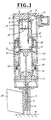
- FIG. 1 shows a combustion gas powered fastener driving tool or nailer according to a first embodiment of the present invention.
- the fastener driving tool is shown with parts in the scavenging and standby position.
- the fastener driving tool includes a tubular housing 1, a cylinder head 2 connected to an upper end of the housing 1, a slidable cylinder 3 disposed in, and extend coaxially with, the housing 1, and a disc piston 4 slidably disposed within the cylinder 3.
- the cylinder head 2, the cylinder 3 and the piston 4 define a combustion chamber 5 in which air and fuel are mixed.
- the cylinder 3 is movable in an axial direction so that an upper end of the cylinder 3 is brought into and out of sealing contact with the cylinder head 2 for closing and opening the combustion chamber 5.
- the cylinder 3 has upper openings 6 extending from the upper end thereof and communicating with an air outlet hole 7 in the housing 1, and lower openings 8 located in a level immediately above the top dead center of the piston 4 and communicating with air inlet holes 9 in the housing 1.
- An electric fan 10 is disposed on the housing 1 in front of the air outlet hole 7 for forcing air to flow along a path extending successively through the air inlet holes 9, through the lower holes 8, through the combustion chamber 5, through the upper holes 6 and through the air outlet hole 7. With this airflow, combustion gases are discharged from the combustion chamber 5, while at the same time, fresh air used for a next cycle of combustion is supplied into the combustion chamber 5.
- the direction of combustion gases and air is indicated by arrows.
- At least one fuel injection nozzle 11 (three in the illustrated embodiment) is disposed within the fuel injection chamber 5 for injecting fuel into the combustion chamber 5.
- the fuel consists of liquefied gas such as liquefied butane gas.
- the fuel injected into the combustion chamber 5 is mixed with air which has been drawn into the combustion chamber 5 by the electric fan 10.
- a spark plug 12 mounted on the cylinder head 2 is disposed within the combustion chamber 5 for firing an air and fuel mixture within the combustion chamber 5 when a trigger switch (not shown) of the tool is activated.
- the pressure in the combustion chamber 5 rises, thereby lowering the piston 4 from the upper driving position (Fig. 1) toward the lower driven position (Fig. 5).
- the downward movement of the piston 4 defines a driving stroke of the piston 4, while the upward movement of the piston 4 defines a return stroke of the piston 4.
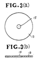
- a turbulence device in the shape of a circular turbulence plate 13 is supported within the combustion chamber 5 by means of a bar 14 extending from the cylinder head 2.
- the turbulence plate 13 has an outside diameter substantially the same as the inside diameter of the cylinder 3 and also has a central aperture or orifice 15. As shown in Figs. 3(a) and 3(b) the diameter of the orifice 15 is considerably smaller than the outside diameter of the turbulence plate 13.
- the piston 4 carries a fastener driving rod or driver 16 for driving a fastener F into a workpiece W.
- the lower end of the fastener driver 16 fits within a tubular barrel 17 connected to the lower end of the housing 1.
- a slidable tubular guide 18 extends coaxially with the cylinder 3 and is connected to a lower end of a ring member 19 slidably fitted between the housing 1 and the cylinder 3.
- the guide 18 is adapted to engage the workpiece W before the barrel 17 and the fastener driver 16.
- a seal ring 20 is slidably fitted over the cylinder 3 and fixed to an inner peripheral wall of the housing 1 for closing the lower openings 8 of the cylinder 3 when the cylinder 3 is moved upwardly relative to the housing 1, as described later.
- An outer compression coil spring 21 is disposed along the inner peripheral wall of the housing 1 and acts between the seal ring 20 and the ring member 19 for urging the latter downward.
- An inner compression coil spring 22 is disposed around the cylinder 3 and acts between an integral flange of the cylinder 3 and the ring member 19 for urging them away from one another.
- the ring member 19 and the cylinder 3 define an annular pressure chamber 23 which communicates with the combustion chamber 5 via communicating holes 24 in the cylinder 3 when the piston 4 is disposed in its lowermost driven position shown in Fig. 5.
- a magazine or feeder 25 is attached to the guide 18 for supplying fasteners F one at a time into the barrel 18 beneath the fastener driver 16, in timed relation to the reciprocating movement of the piston 4.
- fuel such as liquefied butane gas is injected via the fuel injection nozzles 11 into the combustion chamber 5.
- the fuel thus injected mixes with air to form an air and fuel mixture.
- the non-illustrated trigger switch is activated whereupon a spark occurs across the spark plug 12. This spark ignites or fires the air and fuel mixture remote from the piston 4.
- the air and fuel mixture thus fired or combusted in the vicinity of the spark plug 12 expands rapidly and thereby forces the unburnt air and fuel mixture toward the psiton 4 via the orifice 15 of the turbulence plate 13.
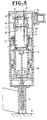
- the fastener driver 16 moves together with the piston 4. As the fastener driver 16 moves toward the workpiece W, the fastener driver 16 encounters a fastener F and then drives the fastener F into the workpiece W, as shown in Fig. 4.
- the piston 4 When the driving stroke of the piston 4 is completed, the piston 4 is disposed in its lowermost driven position (bottom dead center) where piston 4 is located below the communicating holes 24.
- the combustion chamber 5 now communicates via the communicating holes 24 with the pressure chamber 23 so that the high pressure combustion gases are permitted to flow into the pressure chamber 23 and force the cylinder 3 downwardly against the force of the inner spring 22, as shown in Fig. 5.
- the high pressure combustion gages do not yield the outer spring 21 because the spring force of the outer spring 21 is greater than that of the inner spring 22.
- the downward movement of the cylinder 3 opens the upper and lower openings 6, 8, thereby communicating the interior of the combustion chamber 5 with the atmosphere.
- the high pressure combustion gases move from the combustion chamber 5 to the atmosphere via the upper and lower openings 6, 8 and the air inlet and outlet openings 9, 7. Then, fresh air is drawn again by the electric fan 10 into the combustion chamber 5 through the air inlet holes 9 of the housing 1 and through the lower openings 8 of the cylinder 3.
- the combustion chamber 5 is kept at the atmospheric pressure. This permits the inner spring 22 to extend and restore its original shape, so that the cylinder 3 is moved upwardly to a position substantially the same as the position shown in Fig. 4. In this state, the temperature in the combustion chamber 5 is higher than the room temperature.
- the upper and lower openings 6, 8 through which the combustion gases are discharged from the combustion chamber 5 are located above the uppermost driving position (top dead center) of the piston 4, the air and fuel mixture is fully trapped in the combustion chamber 5 until after it is combusted. Since an outflow of the unburnt air and fuel mixture is completely prevented, the rate of fuel consumption of this fastener driving tool is high and there is no danger of accidental explosion of unburned fuel even when the fastener driving tool is used in a badly ventilated working place or site.
- the electric fan 10 disposed outside the cylinder is isolated from high temperatures and hence is durable in construction and reliable in operation.
- the turbulence plate 13 having a single central orifice 15 is also durable and effective to reduce the time period during which the high temperature combustion gases contact the inner peripheral wall of the cylinder 3. With this turbulence plate 13, a high combustion pressure can be obtained.
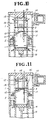
- Figs. 6 and 7 show a combustion gas powered fastener driving tool according to a second embodiment of this invention.
- This fastener driving tool is substantially the same as the fastener driving tool of the first embodiment shown in Figs. 1 through 5 with the exception that the cylinder 3 includes a bulged circumferential portion 26.
- the bulged portion 26 is disposed relative to the circular turbulence plate 13 in such a manner that the bulged portion 26 and the turbulence plate 13 extend in a same plane when the fastener driving tool is in the standby and scavenging condition shown in Fig. 6, and the bulged portion 26 and the turbulence plate 13 extend in different planes when the fastener driving tool is in the operating or driving condition shown in Fig. 7.
- the combustion gases are permitted to flow not only through the orifice 15 but also through an annular space defined between the periphery of the turbulence plate 13 and the bulged circumferential portion 26 of the cylinder 3.
- the combustion gases are, therefore, discharged from the combustion chamber 5 rapidly.
- the bulged portion 26 is upwardly displaced from the turbulence plate 13 and hence turbulence plate 13 closely fits within the cylinder 3.
- the turbulence plate 13 effectively creates turbulent currents in the air and fuel mixture as the mixture is forced downwardly through the central orifice 15.
- the bulged circumferential portion 26 serves as a scavenging promoting means.
- Figs. 8 and 9 fragmentarily show a combustion gas powered fastener driving tool according to a third embodiment of this invention.
- This fastener driving tool differs from the fastener driving tool of the first embodiment shown in Figs. 1 through 5 in that the turbulence device is composed of an inner member 27 and an outer member 28.
- the inner member 27 comprises a circular plate connected by a bar 14 to the cylinder head 2 and having a central orifice 15.
- the circular turbulence plate 27 has an outside diameter smaller than the inside diameter of the cylinder 3.
- the outer member 28 comprises an annular flange integral with and projecting from the inner peripheral wall of the cylinder 3.
- the annular flange 28 has an inside diameter smaller than the outside diameter of the circular turbulence plate 27.
- the circular turbulence plate 27 and the annular flange 28 are releasably engageable in response to reciprocating movement of the cylinder 3 relative to the cylinder head 2. They are disposed such that the circular turbulence plate 27 and the annular flange 28 are spaced from one another to thereby allow the combustion gases to flow through the orifice 15 and through a space between the turbulence plate and the annular flange 28 when the tool is in the standby and scavenging condition (Fig. 8), while the circular turbulence plate 27 and the annular flange 28 engage together to block the flow of combustion gases through a clearance therebetween when the tool is in the driving condition (Fig. 9).
- Figs. 10 and 11 show a portion of a fastener driving tool according to a fourth embodiment of this invention.
- This fastener driving tool includes a two-piece turbulence device which is structurally and functionally identical to the turbulence device of the tool shown in Figs. 8 and 9 except for the following features.
- the turbulence device is composed of an inner member 29 and an outer member 30 releasably engageable in response to reciprocating movement of the cylinder 3 relative to the cylinder head 2.
- the inner member 29 comprises a circular turbulence plate having a central orifice 15 and connected by support arms 31 to the cylinder 3.
- the circular turbulence plate 29 has an outside diameter smaller than the inside diameter of the cylinder 3.
- the outer member 30 comprises an annular disc connected by a bar 14 to the cylinder head 2 and having an outside diameter substantially the same as the inside diameter of the cylinder 3.
- the inside diameter of the annular disc 30 is smaller than the outside diameter of the circular turbulence plate 29.
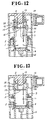
- Figs. 12 and 13 shows a portion of a combustion gas powered fastener driving tool according to a fifth embodiment of this invention.
- the fastener driving tool of this embodiment is similar to the tool of the embodiment shown in Figs. 6 and 7 and differs therefrom in that the cylinder head 2 has a substantially conical inner surface 32 facing the combustion chamber 5 for guiding the combustion gases smoothly to the outside of the tool, thereby accelerating scavenging of the combustion chamber 5.
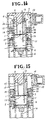
- Figs. 14 and 15 illustrate a portion of a fastener driving tool according to a sixth embodiment of this invention.
- the fastener driving tool of this embodiment is substantially identical to the tool of the embodiment shown in Figs. 12 and 13 except for the following features.
- the cylinder 3 has peripheral holes 33 through which the combustion gases move when they are discharged from the combustion chamber 5.
- a second seal ring 34 is firmly fitted with the housing 1 and has connecting holes 35 extending axially therethrough.
- the peripheral holes 33 are selectively closed by the seal ring 34 in response to the reciprocating movement of the cylinder 3.
- the peripheral holes 33 are disposed in a same plane as the circular turbulence plate 13 and they are not closed by the seal ring 34, as shown in Fig. 14. In this instance, the combustion gases in the combustion chamber 5 are discharged not only through the upper openings and through the discharge hole 7 but also through the peripheral holes 33 and through the connecting holes 35. Conversely, when the cylinder 3 is displaced away from the cylinder head 2 during fastener driving operation, the peripheral holes 33 are closed by the seal ring 34 and they are upwardly displaced out of alignment with the plane of the circular turbulence plate 13.
- Figs. 16 and 17 show a fastener driving tool according to a seventh embodiment of this invention.
- This tool differs from the tool of the embodiment shown in Figs. 14 and 15 in that the electric fan 10 is disposed in a position to cause fresh air to be drawn from the upper and lower openings 6, 8 into the combustion chamber 5 and to move out from the combustion chamber 5 through the peripheral openings 33. More specifically, the electric fan 10 is disposed in front of a discharge hole 36 formed in the housing 1 between the first and second seal rings 20, 34.
- the first seal ring 20 also has connecting holes 20a extending axially therethrough.
- the upper and lower openings 6, 8 serve as air inlet openings
- the peripheral openings 33 serve as air outlet openings.
Landscapes
- Engineering & Computer Science (AREA)
- Chemical & Material Sciences (AREA)
- Combustion & Propulsion (AREA)
- Mechanical Engineering (AREA)
- Portable Nailing Machines And Staplers (AREA)
Claims (17)
- Brenngas-betriebenes Befestiger-Eintreibwerkzeug, welches enthält einen Zylinder (3), einen dichtend mit einem oberen Ende des Zylinders (3) in Eingriff bringbaren Zylinderkopf (2), einen gleitbar innerhalb des Zylinders (3) angeordneten Kolben (4), der zwischen einer obersten Antreibposition und einer untersten angetriebenen Position hin- und herbewegbar ist, wobei der Zylinder (3), der Zylinderkopf (2) und der Kolben (4) eine Brennkammer (5) bestimmen, einen an dem Kolben (4) angebrachten Befestiger-Eintreiber (16), mindestens eine Treibstoff-Einspritzdüse (11), die innerhalb der Brennkammer (5) angeordnet ist zum Einspritzen von Brennstoff in die Brennkammer (5), wo der Brennstoff und Luft miteinander vermischt werden, und eine Zündkerze (12), die an dem Zylinderkopf (2) angebracht und innerhalb der Brennkammer (5) zum Entzünden eines Treibstoff/Luft-Gemisches angeordnet ist, um den Kolben (4) durch einen Antriebshub von der Antriebposition zu der angetriebenen Position zu bewegen, und dadurch den Befestiger-Eintreiber zum Eintreiben eines Befestigers (F) in ein Werkstück (W) zu beaufschlagen, wobei der Zylinder (3) Einlaß- und Auslaßöffnungen (6, 8, 33) besitzt, die über dem Kolben (4) angeordnet sind, wenn der Kolben (4) in seiner obersten Antriebsposition ist, dadurch gekennzeichnet, daß der Zylinder (3) zu dem Zylinderkopf (2) hin und von ihm weg hin- und herbewegbar ist, um die Einlaß- und Auslaßöffnungen (6, 8, 33) zu verschließen und die Brennkammer (5) während der Verbrennung abzudichten, und die Einlaß- und Auslaßöffnungen (6, 8) zu öffnen, um ein Spülen der Brennkammer (5) zuzulassen und den Kolben (4) zurückzuholen nach dem Antriebshub des Kolbens (4), und daß ein Gebläse (10) außerhalb des Zylinders (3) angeordnet ist, um Frischluft von der Einlaßöffnung (8; 6, 8) in die Brennkammer (5) einströmen zu lassen und gleichzeitig Verbrennungsgase von der Brennkammer (5) an die Umgebung durch die Auslaßöffnung (6; 33) zu entlassen.
- Brenngas-betriebenes Befestiger-Eintreibwerkzeug nach Anspruch 1, das weiter enthält Mittel zum Hin- und Herbewegen des Zylinders (3) relativ zu dem Zylinderkopf (2) in zeitlich abgestimmter Beziehung zu dem Antriebshub des Kolbens.
- Brenngas-betriebenes Befestiger-Eintreibwerkzeug nach Anspruch 2, bei dem das Hin- und Herbewege-Mittel enthält ein gleitbar über den Zylinder (3) gepaßtes Ringteil (19), eine Führung (18), die sich von einem Ende des Ringteils (19) zur Anlage an dem Werkstück (W) vor und während des Antriebshubs des Kolbens (4) erstreckt, erstes Federmittel (21), um das Ringteil (19) von dem Zylinderkopf (2) wegzudrängen, zweites Federmittel (22), das zwischen dem Zylinder (3) und dem Ringteil (19) wirkt, um diese auseinander zu drangen, eine zwischen dem Zylinder (3) und dem Ringteil (19) definierte Druckkammer (23) und eine in dem Zylinder (3) definierte Verbindungsöffnung (24) zum Verbinden der Brennkammer (5) mit der Druckkammer (23), wenn der Kolben (3) in seiner untersten angetriebenen Position angeordnet ist.
- Brenngas-betriebenes Befestiger-Eintreibwerkzeug nach Anspruch 1, das weiter enthält ein rohrförmiges Gehäuse (1), das an einem oberen Ende mit dem Zylinderkopf (2) verbunden ist und sich koaxial mit dem Zylinder (3) erstreckt, wobei der Zylinder (3) in dem Gehäuse (1) aufgenommen und das Gebläse (10) an dem Gehäuse (1) angebracht ist.
- Brenngas-betriebenes Befestiger-Eintreibwerkzeug nach Anspruch 4, das weiter enthält einen fest innerhalb des Gehäuses (1) eingepaßten Ring (20) zum Verschließen der Einlaßöffnung (8), wenn der Zylinder (3) zu dem Zylinderkopf (2) hin versetzt ist.
- Brenngas-betriebenes Befestiger-Eintreibwerkzeug nach Anspruch 1, das weiter enthält Mittel (13; 27, 28; 29, 30) in der Brennkammer (5), um in der Brennkammer (5) eine Turbulenz zu erzeugen.
- Brenngas-betriebenes Befestiger-Eintreibwerkzeug nach Anspruch 6, bei dem das Turbulenz-Erzeugungsmittel (13) eine kreisförmige Turbulenzplatte mit einer zentralen Mündung (15) umfaßt, wobei die kreisförmige Turbulenzplatte (13) einem Außendurchmesser besitzt, der im wesentlichen gleich dem Innendurchmesser des Zylinders (3) ist.
- Brenngas-betriebenes Befestiger-Eintreibwerkzeug nach Anspruch 7, bei dem der Zylinderkopf (2) eine der Brennkammer (5) zugewendete, im wesentlichen kegelförmige Innenfläche (32) besitzt.
- Brenngas-betriebenes Befestiger-Eintreibwerkzeug nach Anspruch 7, das weiter Mittel (26) enthält, die mit der kreisförmigen Turbulenzplatte (13) zusammenwirken, um das Spülen der Brennkammer (5) zu unterstützen.
- Brenngas-betriebenes Befestiger-Eintreibwerkzeug nach Anspruch 9, bei dem das Spül-Unterstützungsmittel (26) einen erweiterten Umfangsabschnitt des Zylinders (3) umfaßt, wobei der erweiterte Abschnitt (28) sich in einer gleichen Ebene wie die kreisförmige Turbulenzplatte (13) während des Verbrennungsvorgangs erstreckt und der erweiterte Abschnitt (28) und die kreisförmige Turbulenzplatte (13) nach Vollendung des Antriebshubes des Kolbens (4) sich in unterschiedlichen Ebenen erstrecken.
- Brenngas-betriebenes Befestiger-Eintreibwerkzeug nach Anspruch 10, bei dem der Zylinderkopf (2) eine der Brennkammer (5) zugewendete im wesentlichen konische Innenfläche (32) besitzt.
- Brenngas-betriebenes Befestiger-Eintreibwerkzeug nach Anspruch 6, bei dem das Turbulenz-Verursachungsmittel ein mit dem Zylinderkopf (2) verbundenes Innenteil (27) und ein mit dem Zylinder (3) integrales Außenteil (28) umfaßt, wobei das Innen- und das Außenteil (27, 28) während der Verbrennung in Berührung miteinander gehalten und nach dem Eintreibhub des Kolbens (4) voneinander getrennt werden.
- Brenngas-betriebenes Befestiger-Eintreibwerkzeug nach Anspruch 12, bei dem das Innenteil (27) eine kreisförmige Turbulenzplatte umfaßt mit einer zentralen Mündung (15) und auch mit einem Außendurchmesser, der kleiner ist als der Innendurchmesser des Zylinders (3), das Außenteil (28) einen von einer Innenumfangswand des Zylinders (3) vorstehenden Ringflansch umfaßt, wobei der Ringflansch (28) einen Innendurchmesser besitzt, der kleiner als der Außendurchmesser der kreisförmigen Turbulenzplatte (27) ist.
- Brenngas-betriebenes Befestiger-Eintreibwerkzeug nach Anspruch 6, bei dem das Turbulenz-Verursachungsmittel umfaßt ein mit dem Zylinder (3) verbundenes Innenteil (29) und ein mit dem Zylinderkopf (2) verbundenes Außenteil (30), wobei das Innen- und das Außenteil (29, 30) während der Verbrennung in Berührung miteinander gehalten und nach dem Eintreibhub des Kolbens (4) voneinander getrennt werden.
- Brenngas-betriebenes Befestiger-Eintreibwerkzeug nach Anspruch 14, bei dem das Innenteil (29) eine kreisförmige Turbulenzplatte mit einer zentralen Mündung (15) umfaßt und auch einen Außendurchmesser besitzt, der kleiner als der Innendurchmesser des Zylinders (3) ist, wobei das Außenteil (30) eine Ringscheibe umfaßt mit einem Innendurchmesser, der kleiner als der Außendurchmesser der kreisförmigen Turbulenzplatte (29) ist.
- Brenngas-betriebenes Befestiger-Eintreibwerkzeug nach Anspruch 1, das weiter enthält eine in der Brennkammer (5) angeordnete kreisförmige Turbulenzplatte (13) mit einer zentralen Mündung (15), wobei die kreisförmige Turbulenzplatte (13) einen Außendurchmesser besitzt, der im wesentlichen gleich dem Innendurchmesser des Zylinders (3) ist, die Anzahl der Einlaßöffnungen (6, 8) zwei beträgt und diese Öffnungen in einer Längsrichtung des Zylinders (3) an gegenüberliegenden Seiten der Auslaßöffnung (33) liegen, und weiter einen stationären Dichtring (34) enthält, der um den Zylinder (3) angeordnet ist, um die Auslaßöffnung (33) während der Verbrennung zu verschließen und die Auslaßöffnung (33) nach dem Eintreibhub des Kolbens (4) zu öffnen.
- Brenngas-betriebenes Befestiger-Eintreibwerkzeug nach Anspruch 1, bei dem der Zylinderkpf (2) eine der Brennkammer (5) zugewendete, im wesentlichen kegelförmige Innenfläche (32) besitzt.
Applications Claiming Priority (4)
| Application Number | Priority Date | Filing Date | Title |
|---|---|---|---|
| JP280883/89 | 1989-10-27 | ||
| JP28088389A JPH03142177A (ja) | 1989-10-27 | 1989-10-27 | ガス燃焼式釘打機 |
| JP21275790A JPH04101784A (ja) | 1990-08-10 | 1990-08-10 | ガス燃焼式釘打機 |
| JP212757/90 | 1990-08-10 |
Publications (2)
| Publication Number | Publication Date |
|---|---|
| EP0424941A1 EP0424941A1 (de) | 1991-05-02 |
| EP0424941B1 true EP0424941B1 (de) | 1994-01-05 |
Family
ID=26519414
Family Applications (1)
| Application Number | Title | Priority Date | Filing Date |
|---|---|---|---|
| EP90120492A Expired - Lifetime EP0424941B1 (de) | 1989-10-27 | 1990-10-25 | Mit Verbrennungsgas betriebenes Eintreibwerkzeug für Befestigungsmittel |
Country Status (3)
| Country | Link |
|---|---|
| US (1) | US5090606A (de) |
| EP (1) | EP0424941B1 (de) |
| DE (1) | DE69005786T2 (de) |
Cited By (1)
| Publication number | Priority date | Publication date | Assignee | Title |
|---|---|---|---|---|
| AU2008346772B2 (en) * | 2008-01-04 | 2011-11-24 | Illinois Tool Works Inc. | Single component intake/exhaust valve member, fuel distribution system, and cooling system for combustion-powered fastener-driving tool |
Families Citing this family (45)
| Publication number | Priority date | Publication date | Assignee | Title |
|---|---|---|---|---|
| US5199626A (en) * | 1990-10-05 | 1993-04-06 | Hitachi Koki Company Limited | Combustion gas powered tool |
| US5191861A (en) * | 1991-07-12 | 1993-03-09 | Stanley-Bostitch, Inc. | Internal combustion actuated portable tool |
| US5197646A (en) * | 1992-03-09 | 1993-03-30 | Illinois Tool Works Inc. | Combustion-powered tool assembly |
| US5607272A (en) * | 1995-01-06 | 1997-03-04 | Illinois Tool Works Inc. | Attachment plate for insulation panels |
| FR2730443B1 (fr) * | 1995-02-15 | 1997-04-11 | Spit Soc Prospect Inv Techn | Appareil de scellement a piston propulse par gaz comprime |
| US6123241A (en) | 1995-05-23 | 2000-09-26 | Applied Tool Development Corporation | Internal combustion powered tool |
| US5752643A (en) * | 1995-05-23 | 1998-05-19 | Applied Tool Development Corporation | Internal combustion powered tool |
| US5553764A (en) * | 1995-06-05 | 1996-09-10 | Sencorp | Gas return cylinder for a reciprocating driver in a tool |
| US5799855A (en) * | 1996-02-09 | 1998-09-01 | Illinois Tool Works Inc. | Velocity control and nosepiece stabilizer system for combustion powered tools |
| FR2746690B1 (fr) * | 1996-03-26 | 1998-05-29 | Spit Soc Prospect Inv Techn | Appareil d'entrainement de tampon par masselotte a retour automatique en position du tir |
| US5713313A (en) * | 1997-02-07 | 1998-02-03 | Illinois Tool Works Inc. | Combustion powered tool with dual fans |
| US6041603A (en) * | 1997-12-31 | 2000-03-28 | Porter-Cable Corporation | Internal combustion fastener driving tool accelerator plate |
| US6006704A (en) * | 1997-12-31 | 1999-12-28 | Porter-Cable Corporation | Internal combustion fastener driving tool fuel metering system |
| US6045024A (en) * | 1997-12-31 | 2000-04-04 | Porter-Cable Corporation | Internal combustion fastener driving tool intake reed valve |
| US6016946A (en) * | 1997-12-31 | 2000-01-25 | Porter-Cable Corporation | Internal combustion fastener driving tool shuttle valve |
| US6260519B1 (en) * | 1997-12-31 | 2001-07-17 | Porter-Cable Corporation | Internal combustion fastener driving tool accelerator plate |
| US6016945A (en) * | 1997-12-31 | 2000-01-25 | Porter-Cable Corporation | Internal combustion fastener driving tool manual recycler |
| US6158643A (en) * | 1997-12-31 | 2000-12-12 | Porter-Cable Corporation | Internal combustion fastener driving tool piston and piston ring |
| USD410182S (en) | 1997-12-31 | 1999-05-25 | Porter-Cable Corporation | Internal combustion fastener driving tool |
| US6116489A (en) * | 1998-10-28 | 2000-09-12 | Pow-R-Tools Corporation | Manually operable internal combustion-type impact tool with reduced recycler stroke |
| DE19950352C2 (de) * | 1999-10-19 | 2002-03-07 | Hilti Ag | Tragbares, brennkraftbetriebenes Arbeitsgerät und Verfahren zum Antrieb seines Kolbens |
| DE10007211C2 (de) * | 2000-02-17 | 2003-03-20 | Hilti Ag | Brennkraftbetriebenes Arbeitsgerät, insbesondere Setzgerät für Befestigungselemente |
| DE10028555C1 (de) * | 2000-06-09 | 2001-09-13 | Hilti Ag | Diffusor-Einspritzdüse zum Einspritzen von flüssigem Brenngas bei einem Arbeitsgerät |
| US6755336B2 (en) * | 2000-12-22 | 2004-06-29 | Kevin A. Harper | Return mechanism for a cyclic tool |
| US7051686B2 (en) * | 2001-02-28 | 2006-05-30 | Illinios Tool Works Inc. | Variable volume valve for a combustion powered tool |
| US20020144498A1 (en) | 2001-03-20 | 2002-10-10 | Adams Joseph S. | Combustion chamber system with spool-type pre-combustion chamber |
| US6390162B1 (en) | 2001-05-04 | 2002-05-21 | Donald P. Sahlem | Log splitter |
| US6655570B2 (en) | 2001-05-04 | 2003-12-02 | Illinois Tool Works Inc. | Constant volume valve for a combustion powered tool |
| FR2832344B1 (fr) | 2001-11-21 | 2004-01-23 | Spit Soc Prospect Inv Techn | Appareil de fixation a piston propulse par gaz comprime |
| DE10226878A1 (de) * | 2002-06-17 | 2003-12-24 | Hilti Ag | Gasbetriebenes Setzgerät |
| US6755159B1 (en) * | 2003-01-20 | 2004-06-29 | Illinois Tool Works Inc. | Valve mechanisms for elongated combustion chambers |
| FR2852547B1 (fr) * | 2003-03-19 | 2006-05-12 | Prospection & Inventions | Appareils a fonctionnement a gaz a chambre de pre-compression et chambre de propulsion |
| US6964553B2 (en) * | 2003-05-23 | 2005-11-15 | Illinois Tool Works Inc. | Port for a fan chamber |
| DE602004023998D1 (de) * | 2003-06-02 | 2009-12-24 | Makita Corp | Verbrennungsmotorwerkzeug |
| US6964362B2 (en) * | 2004-02-06 | 2005-11-15 | Illinois Tool Works Inc. | Shock-absorbing system for fastener driving tools |
| WO2006026709A2 (en) * | 2004-08-30 | 2006-03-09 | Black & Decker Inc. | Combustion fastener |
| DE102004043950B4 (de) * | 2004-09-11 | 2006-10-12 | Hilti Ag | Brennkraftbetriebenes Setzgerät |
| EP1899114A4 (de) * | 2005-06-29 | 2009-11-04 | Poly Systems Pty Ltd | Kraftbetriebenes handwerkzeug |
| JP5110251B2 (ja) * | 2006-08-25 | 2012-12-26 | マックス株式会社 | ガス燃焼式打込み工具 |
| JP5070957B2 (ja) * | 2007-06-29 | 2012-11-14 | マックス株式会社 | ガス燃焼式打込み工具 |
| DE102007055904A1 (de) * | 2007-12-21 | 2009-06-25 | Hilti Aktiengesellschaft | Brennkraftbetriebenes Setzgerät |
| US8646671B2 (en) | 2008-01-04 | 2014-02-11 | Illinois Tool Works Inc. | Combustion chamber and cooling system for fastener-driving tools |
| DE102008000167A1 (de) * | 2008-01-29 | 2009-07-30 | Hilti Aktiengesellschaft | Brennkraftbetriebenes Setzgerät |
| CN201389838Y (zh) * | 2009-03-27 | 2010-01-27 | 张汉勤 | 射钉发射装置 |
| FR3000914B1 (fr) * | 2013-01-16 | 2015-01-09 | Illinois Tool Works | Outil de fixation a gaz a reinjection d'air |
Family Cites Families (6)
| Publication number | Priority date | Publication date | Assignee | Title |
|---|---|---|---|---|
| US4403722A (en) * | 1981-01-22 | 1983-09-13 | Signode Corporation | Combustion gas powered fastener driving tool |
| US4483474A (en) * | 1981-01-22 | 1984-11-20 | Signode Corporation | Combustion gas-powered fastener driving tool |
| IN157475B (de) * | 1981-01-22 | 1986-04-05 | Signode Corp | |
| US4483473A (en) * | 1983-05-02 | 1984-11-20 | Signode Corporation | Portable gas-powered fastener driving tool |
| US4773581A (en) * | 1986-06-13 | 1988-09-27 | Hitachi Koki Company, Ltd. | Combustion gas powered tool |
| US4712379A (en) * | 1987-01-08 | 1987-12-15 | Pow-R Tools Corporation | Manual recycler for detonating impact tool |
-
1990
- 1990-10-25 DE DE90120492T patent/DE69005786T2/de not_active Expired - Lifetime
- 1990-10-25 EP EP90120492A patent/EP0424941B1/de not_active Expired - Lifetime
- 1990-10-26 US US07/603,659 patent/US5090606A/en not_active Expired - Lifetime
Cited By (1)
| Publication number | Priority date | Publication date | Assignee | Title |
|---|---|---|---|---|
| AU2008346772B2 (en) * | 2008-01-04 | 2011-11-24 | Illinois Tool Works Inc. | Single component intake/exhaust valve member, fuel distribution system, and cooling system for combustion-powered fastener-driving tool |
Also Published As
| Publication number | Publication date |
|---|---|
| US5090606A (en) | 1992-02-25 |
| DE69005786D1 (de) | 1994-02-17 |
| DE69005786T2 (de) | 1994-04-28 |
| EP0424941A1 (de) | 1991-05-02 |
Similar Documents
| Publication | Publication Date | Title |
|---|---|---|
| EP0424941B1 (de) | Mit Verbrennungsgas betriebenes Eintreibwerkzeug für Befestigungsmittel | |
| EP0056989B1 (de) | Tragbares, gasgetriebenes Werkzeug mit Linearmotor | |
| US4913331A (en) | Internal-combustion piston driving apparatus having a decompression channel | |
| US7305941B2 (en) | Combustion type power tool having motor suspension arrangement | |
| US6892524B1 (en) | Latching mechanism for combustion chamber plate of a fastener driving tool | |
| US7490582B2 (en) | Combustion type power tool having fin for effectively cooling cylinder | |
| CN101511546A (zh) | 燃烧式动力工具 | |
| EP1449624B1 (de) | Verbrennungsmotorwerkzeug | |
| EP2240300B1 (de) | Einteiliges einlass-/auslassventilelement für ein brennkraftbetriebenes eintreibwerkzeug | |
| US7305940B2 (en) | Combustion-type power tool having ignition proof arrangement | |
| US6695195B2 (en) | Combustion-powered nail gun | |
| US20050263113A1 (en) | Combustion type nailing machine | |
| JPH0563778U (ja) | 連打式釘打機の釘打込み深さ調整装置 | |
| WO2022123369A1 (en) | Gas operating system for bump-fired fastener-driving tool | |
| JP2003136424A (ja) | ガス釘打機 | |
| JPS63147012A (ja) | 内燃式ピストン駆動装置の掃気装置 |
Legal Events
| Date | Code | Title | Description |
|---|---|---|---|
| PUAI | Public reference made under article 153(3) epc to a published international application that has entered the european phase |
Free format text: ORIGINAL CODE: 0009012 |
|
| AK | Designated contracting states |
Kind code of ref document: A1 Designated state(s): DE FR GB |
|
| 17P | Request for examination filed |
Effective date: 19911021 |
|
| 17Q | First examination report despatched |
Effective date: 19930222 |
|
| GRAA | (expected) grant |
Free format text: ORIGINAL CODE: 0009210 |
|
| AK | Designated contracting states |
Kind code of ref document: B1 Designated state(s): DE FR GB |
|
| ET | Fr: translation filed | ||
| REF | Corresponds to: |
Ref document number: 69005786 Country of ref document: DE Date of ref document: 19940217 |
|
| PLBE | No opposition filed within time limit |
Free format text: ORIGINAL CODE: 0009261 |
|
| STAA | Information on the status of an ep patent application or granted ep patent |
Free format text: STATUS: NO OPPOSITION FILED WITHIN TIME LIMIT |
|
| 26N | No opposition filed | ||
| REG | Reference to a national code |
Ref country code: GB Ref legal event code: IF02 |
|
| PGFP | Annual fee paid to national office [announced via postgrant information from national office to epo] |
Ref country code: DE Payment date: 20091022 Year of fee payment: 20 |
|
| PGFP | Annual fee paid to national office [announced via postgrant information from national office to epo] |
Ref country code: FR Payment date: 20091029 Year of fee payment: 20 Ref country code: GB Payment date: 20091021 Year of fee payment: 20 |
|
| REG | Reference to a national code |
Ref country code: GB Ref legal event code: PE20 Expiry date: 20101024 |
|
| PG25 | Lapsed in a contracting state [announced via postgrant information from national office to epo] |
Ref country code: GB Free format text: LAPSE BECAUSE OF EXPIRATION OF PROTECTION Effective date: 20101024 |
|
| PG25 | Lapsed in a contracting state [announced via postgrant information from national office to epo] |
Ref country code: DE Free format text: LAPSE BECAUSE OF EXPIRATION OF PROTECTION Effective date: 20101025 |