EP0424867B1 - Kühlvorrichtung für Elektromotoren - Google Patents
Kühlvorrichtung für Elektromotoren Download PDFInfo
- Publication number
- EP0424867B1 EP0424867B1 EP90120281A EP90120281A EP0424867B1 EP 0424867 B1 EP0424867 B1 EP 0424867B1 EP 90120281 A EP90120281 A EP 90120281A EP 90120281 A EP90120281 A EP 90120281A EP 0424867 B1 EP0424867 B1 EP 0424867B1
- Authority
- EP
- European Patent Office
- Prior art keywords
- motor housing
- cooling
- cooling device
- motor
- channels
- Prior art date
- Legal status (The legal status is an assumption and is not a legal conclusion. Google has not performed a legal analysis and makes no representation as to the accuracy of the status listed.)
- Expired - Lifetime
Links
- 238000001816 cooling Methods 0.000 title claims description 50
- XAGFODPZIPBFFR-UHFFFAOYSA-N aluminium Chemical compound [Al] XAGFODPZIPBFFR-UHFFFAOYSA-N 0.000 claims description 3
- 229910052782 aluminium Inorganic materials 0.000 claims description 3
- 239000004020 conductor Substances 0.000 claims 1
- 238000004519 manufacturing process Methods 0.000 description 4
- 238000004804 winding Methods 0.000 description 4
- 238000010438 heat treatment Methods 0.000 description 3
- 238000009749 continuous casting Methods 0.000 description 2
- 239000002826 coolant Substances 0.000 description 2
- 230000017525 heat dissipation Effects 0.000 description 2
- 238000000034 method Methods 0.000 description 2
- 229910001060 Gray iron Inorganic materials 0.000 description 1
- 238000005253 cladding Methods 0.000 description 1
- 238000010276 construction Methods 0.000 description 1
- 230000005284 excitation Effects 0.000 description 1
- 238000007373 indentation Methods 0.000 description 1
- 238000012805 post-processing Methods 0.000 description 1
- 238000012545 processing Methods 0.000 description 1
- 230000005855 radiation Effects 0.000 description 1
- 230000008646 thermal stress Effects 0.000 description 1
- 230000007704 transition Effects 0.000 description 1
Images

Classifications
-
- H—ELECTRICITY
- H02—GENERATION; CONVERSION OR DISTRIBUTION OF ELECTRIC POWER
- H02K—DYNAMO-ELECTRIC MACHINES
- H02K9/00—Arrangements for cooling or ventilating
- H02K9/14—Arrangements for cooling or ventilating wherein gaseous cooling medium circulates between the machine casing and a surrounding mantle
-
- D—TEXTILES; PAPER
- D02—YARNS; MECHANICAL FINISHING OF YARNS OR ROPES; WARPING OR BEAMING
- D02J—FINISHING OR DRESSING OF FILAMENTS, YARNS, THREADS, CORDS, ROPES OR THE LIKE
- D02J13/00—Heating or cooling the yarn, thread, cord, rope, or the like, not specific to any one of the processes provided for in this subclass
- D02J13/005—Heating or cooling the yarn, thread, cord, rope, or the like, not specific to any one of the processes provided for in this subclass by contact with at least one rotating roll
Definitions
- the cylindrical part of the motor housing is provided on its periphery with axially parallel cooling fins which are surrounded on the outside by a cover plate.
- AT-B 294 967 shows a cooling arrangement with several flow paths for electrical machines, in which suction openings for the coolant are provided both in the machine housing and in the end shields.
- the stator coolant flow runs from the center of the housing along the back of the stator against the end shields.
- the rotor has axial flow channels and a fan on both sides. Each axial rotor channel is connected on the one hand via a passage in the fan hub to the inlet openings provided in the end shields and on the other hand via the fan blade ring to the outlet openings of the machine housing.
- US Pat. No. 4,353,002 describes an assembly consisting of an electric motor and a heating godet, the continuous shaft of which carries a first fan wheel on the end remote from the godet for cooling the motor end shield remote from the godet and a second fan wheel for cooling the bearing plate near the godet between the motor and the godet.
- the invention is based in claim 1 on a cooling device known from EP-A 0288429.
- the jacket shell placed there on a smooth cylindrical motor housing is provided on the outside with axially parallel cooling fins, but the essential cooling takes place through the cooling air pushed through by a blower between the motor housing and jacket shell.
- the jacket shell is supported by a few thin-walled support feet on the outer surface of the motor housing, so that these support feet divide the annular space between the motor housing and the jacket shell into several cooling channels.
- cooling fins are additionally attached to the outer circumference of the otherwise smooth motor housing and protrude into the cooling channels.
- the jacket shell can be composed of several partial shells, which are designed as extruded profiles.
- the invention is characterized in claim 1. With it, it is possible to simplify the construction of such a cooling device and to facilitate its manufacture, while at the same time improving its effectiveness, because the heat dissipation via the webs creates an additional, highly effective heat dissipation. No changes or additional processing is required on the motor itself or on its housing. While motor housings with molded cooling fins usually consist of gray cast iron, the use of aluminum is recommended for the production of the profile jacket segments according to the invention, which is easy to machine and has particularly good thermal conductivity properties. A profile jacket divided into segments can be produced inexpensively using the continuous casting process and can be easily assembled and, if necessary, disassembled.
- the two shaft bearings 4 and 5 are seated in the two end walls 1 and 2 of the motor frame 3.
- the motor shaft 6 carries the rotor 7 between the end walls 1 and 2 and projects beyond the end walls on both sides.
- a support flange 9 is attached via an intermediate flange 8, which is from the frame 10 of a machine, e.g. a yarn treatment machine.
- the end 11 of the motor shaft 6 protruding from the left end wall 1 is connected via a hub 12 to the casing 13 of a godet heated by an inductor 14.
- the fixed inductor 14, consisting of core 15 and excitation winding 16, is held in a known manner by the machine frame 10.
- the rotating part 18 of a known rotary transformer serving as a measured value transmitter is fastened, the stationary part 19 of which is supported by the right end wall 2 by means of a holding plate 20.
- the winding of the rotating part 18 is connected via a line 21 guided through the hollow motor shaft 6 to a temperature sensor 22 arranged in the godet jacket 13 and the winding of the fixed part 19 to a controller controlling the power supply to the inductor winding 16.
- an impeller 23 sits on the right shaft end 17.
- This housing is surrounded by a profile jacket 25, the cross section of which can be seen in FIG. It is only one of four quadrants of the profile cladding shown. It could also be made in one piece. However, the assembly from several segments is simpler, but in particular the manufacture of such profiles designed as a segment, for example as a quadrant or a circle of thirds, is simpler than a self-contained jacket which could be shrunk onto the smooth cylindrical motor housing 3.
- the individual segments are screwed together, namely by means of screws which protrude through the flange pieces 26 and are screwed into nuts or threaded strips held by the counter piece 27.
- a shoulder 28 and a corresponding recess 29 ensure a good heat-conducting transition between the individual segments.
- the profile jacket segment shown in FIG. 2 extends over 90 ° of the circumference, the individual segments could also cover other, possibly different, angle ranges, for example 120 °.
- the profile jacket 25 forms cooling passages 30 extending essentially parallel to the motor axis and having an essentially circular cross section. These can be formed entirely within the profile jacket or, as shown in FIG. 2, open towards the housing jacket 3.
- the cross section can also deviate from the circular shape, for example, like the channel 30a, can be U-shaped.
- the outer jacket wall 31 is provided with indentations 32, on the one hand to enlarge the radiating surface and, on the other hand, to have the same wall thickness as possible and thereby to avoid thermal stresses.
- the inner surfaces 33 of the webs 34 of the profile jacket 25 and the end pieces 35 located between the individual cooling channels and which are in contact with the motor housing 3 are curved in accordance with the outer diameter of the tubular motor housing 3 so that they rest on the motor housing over a large area and good heat transfer is ensured.
- the profile jacket 25 is preferably made of aluminum, it can be drawn as an extruded profile. Such profiles can be manufactured in a continuous casting process with high dimensional accuracy, so that no post-processing is required. A smooth cylindrical motor housing is also easy to manufacture.
- a hood 37 provided with an air inlet grille 36 covers the end wall 2 and the impeller 23, and its outer edge 38 is aligned with the outer wall 31 of the profile casing 25.
- the impeller 23 driven by the motor shaft 6 sucks cooling air L through the grille 36 and presses them into the cooling channels 30. This not only cools the casing of the motor housing, but also the air flow L that arises in the space between the hood 37 and the end wall 2 cools the bearing 5.
- the air emerging at the left end of the cooling channels is deflected radially inward towards the shaft 6 by a guide ring 39 and thereby cools the part of the shaft 6 adjacent to the bearing 4.
- the stationary guide ring 39 forms inlet openings 40 of a radial fan, the fan wheel 41 of which on the Galette adjacent part of the shaft 6 is attached over a large area and good heat conduction. It presses the cooling air L initially flowing from the inlet openings 40 onto the shaft 6 radially outwards, where the cooling air L leaves the cooling device via the outlets 42.
- the guide ring 39 is part of the intermediate flange 8.
- the inner ring of the bearing 4 is supported on the one hand on a shaft shoulder 43 and on the other hand is held by a clamping ring 44.
- the outer ring is held in the end wall 1 by means of a pressure plate 45.
- the cooled impeller 41 shields the bearing 4 against the heat radiation from the godet 13.
Landscapes
- Engineering & Computer Science (AREA)
- Power Engineering (AREA)
- Textile Engineering (AREA)
- Motor Or Generator Cooling System (AREA)
- Structures Of Non-Positive Displacement Pumps (AREA)
Description
- Bei einer aus EP-A 0235 505 bekannten Kühlvorrichtung für Elektromotoren ist der zylindrische Teil des Motorgehäuses an seinem Umfang mit achsparallelen Kühlrippen versehen, die außen von einem Abdeckblech umgeben sind. Zwischen den Kühlrippen entstehen somit mehrere achsparallele, über den Umfang des Motorgehäuses verteilt angeordnete Kühlkanäle, in welche ein Gebläse Kühlluft für das Motorgehäuse und die Wellenlager fördert. Um einen guten Wärmeübergang zwischen Kühlrippen und Abdeckblech zu gewährleisten und durch Vibrationen des Abdeckblechs verursachte zusätzliche Geräusche zu vermeiden, ist es dabei erforderlich, die Außenflächen der Kühlrippen spanabhebend zu bearbeiten, damit das Abdeckblech gut aufliegt.
- AT-B 294 967 zeigt eine Kühlanordnung mit mehreren Strömungswegen für elektrische Maschinen, bei welcher sowohl im Maschinengehäuse als auch in den Lagerschilden Ansaugöffnungen für das Kühlmittel vorgesehen sind. Der Ständerkühlmittelstrom verläuft von der Gehäusemitte aus entlang des Ständerrückens gegen die Lagerschilde. Der Rotor weist axiale Strömungskanäle und beidseitig einen Lüfter auf. Jeder axiale Rotorkanal steht einerseits über einen Durchgang in der Lüfternabe mit den in den Lagerschilden vorgesehenen Eintrittsöffnungen und andererseits über den Lüfterschaufelkranz mit den Austrittsöffnungen des Maschinengehäuses in Verbindung.
- In US-A 4 353 002 ist ein aus einem Elektromotor und einer Heizgalette bestehendes Aggregat beschrieben, dessen durchgehende Welle auf dem galettenfernen Ende ein erstes Lüfterrad zur Kühlung des galettenfernen Motorlagerschilds sowie zwischen Motor und Galette ein zweites Lüfterrad zur Kühlung des galettennahen Lagerschilds trägt.
- Die Erfindung geht im Anspruch 1 von einer aus EP-A 0288429 bekannten Kühlvorrichtung aus. Die dort auf ein glattes zylindrisches Motorgehäuse aufgesetzte Mantelschale ist zwar auf ihrer Außenseite mit achsparallelen Kühlrippen versehen, die wesentliche Kühlung erfolgt aber durch die von einem Gebläse zwischen Motorgehäuse und Mantelschale hindurchgedrückte Kühlluft. Die Mantelschale stützt sich über einige wenige dünnwandige Stützfüße an der Außenfläche des Motorgehäuses ab, so daß diese Stützfüße den Ringraum zwischen Motorgehäuse und Mantelschale in mehrere Kühlkanäle unterteilen. Bei einer Ausführungsform dieser bekannten Kühlvorrichtung sind zusätzlich am Außenumfang des ansonsten glatten Motorgehäuses Kühlrippen angebracht, welche in die Kühlkanäle hineinragen. Die Mantelschale kann aus mehreren Teilschalen zusammengesetzt sein, die als stranggepreßte Profile ausgebildet sind.
- Die Erfindung ist im Anspruch 1 gekennzeichnet. Mit ihr gelingt es, den Aufbau einer solchen Kühlvorrichtung zu vereinfachen und ihre Herstellung zu erleichtern und dabei gleichzeitig ihre Wirksamkeit noch zu verbessern, weil die Wärmeableitung über die Stege einen zusätzlichen hochwirksamen Wärmeabfluß schafft. Am Motor selbst bzw. an seinem Gehäuse sind keine Änderungen oder zusätzlichen Bearbeitungen erforderlich. Während Motorgehäuse mit angeformten Kühlrippen üblicherweise aus Grauguß bestehen, empfiehlt sich für die Herstellung der erfindungsgemäßen Profilmantelsegmente die Verwendung von Aluminium, was leicht zu bearbeiten ist und besonders gute Wärmeleiteigenschaften hat. Ein in Segmente unterteilter Profilmantel kann im Stranggußverfahren kostengünstig hergestellt werden und läßt sich einfach montieren und gegebenenfalls demontieren.
- Vorteilhafte Ausgestaltungen der Erfindung ergeben sich aus den Unteransprüchen. Dabei ist aus DE-A 27 37 292 ein Elektromotor zum Amtrieb einer Heizgalette bekannt, bei dem auf dem zwischen Motor und Galette befindlichen Teil der Motorwelle ein Gebläserad sitzt. Es saugt an der Stirnseite des Motorgehäuses Kühlluft radial nach innen, leitet sie ein Stück entlang der Welle und drückt die Luft dann wieder radial nach außen. Außerdem ist am galettenfernen Ende der Motorwelle auf diese ein zweites Gebläserad aufgesetzt, welches zusammen mit einer am benachbarten Ende des Motorgehäuses befestigten Strömungsleitkappe Kühlluft achsparallel zwischen die Kühlrippen des Motorgehäuses bläst.
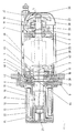
- Die Erfindung wird nachfolgend anhand eines in den Zeichnungen wiedergegebenen Ausführungsbeispiels erläutert. Dabei zeigt
- Fig.1
- einen Elektromotor mit von ihm angetriebener Heizgalette und der Kühlvorrichtung in einem achsparallelen Teilschnitt und
- Fig.2
- einen Teilschnitt senkrecht zur Motorachse durch eines der Profilmantelsegmente.
- In den beiden Stirnwänden 1 und 2 des Motorgestells 3 sitzen die beiden Wellenlager 4 und 5. Die Motorwelle 6 trägt zwischen den Stirnwänden 1 und 2 den Rotor 7 und ragt beidseitig über die Stirnwände hinaus. An der linken Stirnwand 1 ist über einen Zwischenflansch 8 ein Tragflansch 9 befestigt, der vom Rahmen 10 einer Maschine, z.B. einer Garnbehandlungsmaschine, getragen wird. Das aus der linken Stirnwand 1 herausragende Ende 11 der Motorwelle 6 ist über eine Nabe 12 mit dem Mantel 13 einer durch einen Induktor 14 beheizten Galette verbunden. Der ortsfeste Induktor 14, bestehend aus Kern 15 und Erregerwicklung 16, wird in bekannter Weise vom Maschinenrahmen 10 gehalten. Auf dem aus der rechten Stirnwand 2 herausragenden Ende 17 der Motorwelle 6 ist der rotierende Teil 18 eines als Meßwertübertrager dienenden bekannten Drehtransformators befestigt, dessen stationärer Teil 19 mittels einer Halteplatte 20 von der rechten Stirnwand 2 getragen wird. Die Wicklung des rotierenden Teils 18 ist über eine durch die hohle Motorwelle 6 geführte Leitung 21 an einen im Galettenmantel 13 angeordneten Temperaturfühler 22 und die Wicklung des feststehenden Teils 19 an einen die Stromzufuhr zur Induktorwicklung 16 steuernden Regler angeschlossen. Ferner sitzt auf dem rechten Wellenende 17 ein Gebläserad 23. Die beiden Stirnwände 1 und 2 bilden zusammen mit dem dazwischenliegenden Mantelteil 3 ein rohrförmiges zylindrisches Gehäuse.
- Dieses Gehäuse ist von einem Profilmantel 25 umgeben, dessen Querschnitt aus Fig.2 ersichtlich ist. Es ist nur einer von vier Quadranten des Profilmantels dargestellt. Er könnte auch einstückig ausgebildet sein. Der Zusammenbau aus mehreren Segmenten ist jedoch einfacher, insbesondere aber ist die Herstellung solcher als Segment, z.B. als Quadrant oder Drittelkreis ausgestalteter Profile einfacher als ein in sich geschlossener Mantel, der auf das glatte zylindrische Motorgehäuse 3 aufgeschrumpft werden könnte. Die einzelnen Segmente werden im gezeigten Beispiel miteinender verschraubt, nämlich mittels Schrauben, welche durch die Flanschstücke 26 hindurchragen und in vom Gegenstück 27 gehaltene Muttern oder Gewindeleisten eingeschraubt sind. Dabei sorgen eine Ansatzleiste 28 und eine entsprechende Ausnehmung 29 für einen gut wärmeleitenden Übergang zwischen den einzelnen Segmenten. Während sich das in Fig.2 gezeigte Profilmantelsegment über 90° des Umfangs erstreckt, könnten die einzelnen Segmente auch andere, gegebenenfalls unterschiedliche Winkelbereiche abdecken, z.B. 120°. Der Profilmantel 25 bildet sich parallel zur Motorachse erstreckende Kühlkanäle 30 von im wesentlichen kreisförmigem Querschnitt. Diese können vollständig innerhalb des Profilmantels gebildet oder, wie in Fig.2 gezeigt, zum Gehäusemantel 3 hin offen sein. Der Querschnitt kann auch von der Kreisform abweichen, beispielsweise wie der Kanal 30a U-förmig sein. Die äußere Mantelwand 31 ist mit Einbuchtungen 32 versehen, um einerseits die abstrahlende Oberfläche zu vergrößern und andererseits eine möglichst gleiche Wandstärke zu haben und hierdurch Wärmespannungen zu vermeiden. Die am Motorgehäuse 3 anliegenden Innenflächen 33 der zwischen den einzelnen Kühlkanälen befindlichen Stege 34 des Profilmantels 25 und der Endstücke 35 sind dem Außendurchmesser des rohrförmigen Motorgehäuses 3 entsprechend gewölbt, damit sie großflächig auf dem Motorgehäuse aufliegen und ein guter Wärmeübergang gewährleistet ist. Der Profilmantel 25 besteht vorzugsweise aus Aluminium, er kann als Strangprofil gezogen werden. Solche Profile lassen sich im Stranggußverfahren mit hoher Maßhaltigkeit herstellen, so daß keine Nachbearbeitung erforderlich ist. Ein glattes zylindrisches Motorgehäuse ist ebenfalls leicht herstellbar.
- Eine mit einem Lufteinlaßgitter 36 versehene Haube 37 deckt die Stirnwand 2 und das Gebläserad 23 ab, und ihr äußerer Rand 38 fluchtet mit der Außenwand 31 des Profilmantels 25. Das von der Motorwelle 6 angetriebene Gebläserad 23 saugt durch das Gitter 36 hindurch Kühlluft L an und drückt sie in die Kühlkanäle 30. Hierdurch wird nicht nur der Mantel des Motorgehäuses gekühlt, sondern der im Raum zwischen Haube 37 und Stirnwand 2 entstehende Luftstrom L kühlt zugleich das Lager 5.
- Die am linken Ende der Kühlkanäle austretende Luft wird durch einen Leitring 39 radial nach innen zur Welle 6 hin abgelenkt und kühlt dabei den dem Lager 4 benachbarten Teil der Welle 6. Der stationäre Leitring 39 bildet Einlaßöffnungen 40 eines Radialgebläses, dessen Gebläserad 41 auf dem der Galette benachbarten Teil der Welle 6 großflächig und gut wärmeleitend befestigt ist. Es drückt die zunächst aus den Einlaßöffnungen 40 auf die Welle 6 zuströmende Kühlluft L radial nach außen, wo die Kühlluft L über die Auslässe 42 die Kühlvorrichtung verläßt. Durch die großflächige Anlage des Gebläserads 41 an der Welle 6 wird dieser der induktiv beheizten Galette benachbarte Teil der Welle 6 zusätzlich gekühlt und der Wärmeübergang von der Galette und vom Induktor 14 auf das galettennahe Lager 4 vermindert. Dies verringert die Lagertemperatur erheblich und erhöht die Lebensdauer des Lagers. Im gezeigten Beispiel ist der Leitring 39 Teil des Zwischenflansches 8. Der Innenring des Lagers 4 stützt sich einerseits an einem Wellenabsatz 43 ab und wird andererseits durch einen Klemmring 44 gehalten. Der Außenring ist mittels einer Druckplatte 45 in der Stirnwand 1 gehalten. Das gekühlte Gebläserad 41 schirmt das Lager 4 gegen die Wärmestrahlung der Galette 13 ab.
Claims (9)
- Kühlvorrichtung für Elektromotoren, insbesondere Antriebsmotoren von Heizgaletten, mita) einem als glattes zylindrisches Rohr (3) ausgebildeten Motorgehäuse (1,2,3);b) einem auf das Motorgehäuse (3) aufgesetzten und dieses umgebenden schalenförmigen Profilmantel (25) aus gut wärmeleitendem Werkstoff;c) mehreren in Achsrichtung verlaufenden und über den Gehäuseumfang verteilt angeordneten Kühlkanälen (30) im Profilmantel (25); sowied) einem am abtriebsfernen Ende des Motorgehäuses Kühlluft (L) in die Kühlkanäle fördernden Gebläse (23), dessen Rotor mit der Motorwelle (6) verbunden ist;dadurch gekennzeichnet, daße) eine Vielzahl von Kühlkanälen (30,30a) gleichmäßig über den Gehäuseumfang (3) verteilt angeordnet ist und die einzelnen Kühlkanäle durch eine entsprechende Vielzahl der Wärmeableitung von der Äußeren Mantelfläche (33) des Motorgehäuses zum Profilmantel dienender achsparalleler Stege (34) des Profilmantels (25) voneinander getrennt sind; undf) die am Motorgehäuse (3) anliegenden Endflächen (33) dieser Wärmeableitstege (34) dem Durchmesser des Motorgehäuses entsprechend gewölbt sind und die Stege mit ihrer gesamten Endfläche am Motorgehäuse (3) anliegen.
- Kühlvorrichtung nach Anspruch 1, dadurch gekennzeichnet, daß die Kühlkanäle (30,30a) im Profilmantel (25) zur Oberfläche des Motorgehäuses (1,2,3) hin offen sind.
- Kühlvorrichtung nach Anspruch 1 oder 2, dadurch gekennzeichnet, daß der Profilmantel (25) aus mehreren jeweils einen Teilwinkelbereich des Motorgehäuseumfangs bedeckenden Segmenten besteht.
- Kühlvorrichtung nach Anspruch 1,2 oder 3, dadurch gekennzeichnet, daß die Kühlkanäle (30) annähernd kreisförmigen Querschnitt haben.
- Kühlvorrichtung nach einem der Ansprüche 1 bis 4, dadurch gekennzeichnet, daß der Profilmantel (25) aus Aluminium besteht.
- Kühlvorrichtung nach einem der Ansprüche 1 bis 5, dadurch gekennzeichnet, daß am abtriebsnahen Ende des Motorgehäuses (3) den Austrittsenden der Kühlkanäle (30,30a) gegenüberstehend die Einlaßöffnungen (40) eines Radialgebläses (39,41) angeordnet sind, dessen Gebläserad (41) großflächig auf der Motorwelle (6) befestigt ist
- Kühlvorrichtung nach Anspruch 6, dadurch gekennzeichnet, daß Luftführungskanäle im Radialgebläse von den Einlaßöffnungen (40) zunächst in Richtung zur Motorwelle (6) hin ausgerichtet und anschließend U-förmig radial nach außen abgebogen sind und in Austrittsöffnungen (42) münden.
- Kühlvorrichtung nach Anspruch 7, dadurch gekennzeichnet, daß die dem Motor (3,7) abgewandte Begrenzungswand der nach außen führenden Teile (42) der Luftführungskanäle durch den Tragflansch (9) eines vom Motor angetriebenen rotierenden Bauteils, z.B. einer induktiv beheizten Galette (13,14) gebildet ist.
- Kühlvorrichtung nach Anspruch 8, dadurch gekennzeichnet, daß die den Luftstrom (L) radial nach außen leitenden Teile der Luftführungskanäle zwischen Tragflansch (9) und Gebläserad (41) einerseits sowie einem stationären Leitring (39) andererseits gebildet sind, der zusammen mit der abtriebsseitigen Stirnwand (1) des Motorgehäuses (3) die den Luftstrom (L) nach innen leitenden Teile der Luftführungskanäle bildet.
Applications Claiming Priority (2)
| Application Number | Priority Date | Filing Date | Title |
|---|---|---|---|
| DE8912578U DE8912578U1 (de) | 1989-10-24 | 1989-10-24 | Kühlvorrichtung für Elektromotoren |
| DE8912578U | 1989-10-24 |
Publications (2)
| Publication Number | Publication Date |
|---|---|
| EP0424867A1 EP0424867A1 (de) | 1991-05-02 |
| EP0424867B1 true EP0424867B1 (de) | 1994-07-20 |
Family
ID=6843953
Family Applications (1)
| Application Number | Title | Priority Date | Filing Date |
|---|---|---|---|
| EP90120281A Expired - Lifetime EP0424867B1 (de) | 1989-10-24 | 1990-10-23 | Kühlvorrichtung für Elektromotoren |
Country Status (2)
| Country | Link |
|---|---|
| EP (1) | EP0424867B1 (de) |
| DE (2) | DE8912578U1 (de) |
Cited By (2)
| Publication number | Priority date | Publication date | Assignee | Title |
|---|---|---|---|---|
| DE19843990C1 (de) * | 1998-09-25 | 1999-08-19 | Dienes Apparatebau Gmbh | Integriertes Galettenaggregat |
| CN110449232A (zh) * | 2019-01-01 | 2019-11-15 | 仲从宝 | 上置机头连体阻隔挡板抽排风冷散热绞肉机 |
Families Citing this family (12)
| Publication number | Priority date | Publication date | Assignee | Title |
|---|---|---|---|---|
| DE4330648C2 (de) * | 1993-09-10 | 1995-11-23 | Hella Kg Hueck & Co | Radialpumpe |
| DE29606474U1 (de) * | 1996-04-09 | 1997-08-07 | Siemens AG, 80333 München | Maschineneinheit mit mehreren an deren Gehäuseumfang angeordneten Kühlsegmenten |
| DE19757605C2 (de) * | 1997-12-23 | 2003-03-13 | Siemens Ag | Elektromotor mit Kühlung |
| DE10022146A1 (de) * | 2000-05-08 | 2001-11-15 | Baumueller Nuernberg Gmbh | Ständer mit Kühlrohren für eine elektrische Maschine sowie Verfahren zu dessen Herstellung |
| JP4106277B2 (ja) * | 2001-05-21 | 2008-06-25 | バルマーク アクチエンゲゼルシヤフト | ゴデット |
| DE102004048461A1 (de) * | 2004-10-05 | 2006-04-27 | Siemens Ag | Gehäuse für eine elektrische Maschine |
| US20090079278A1 (en) * | 2007-09-20 | 2009-03-26 | Kramer Dennis A | Segmented motor cooling jacket |
| US8161643B2 (en) | 2007-09-20 | 2012-04-24 | Arvinmeritor Technology, Llc | Method for forming a cooling jacket for an electric motor |
| JP5689448B2 (ja) * | 2012-09-28 | 2015-03-25 | ファナック株式会社 | 高効率の空冷構造を有するモータ |
| JP7053246B2 (ja) * | 2017-12-21 | 2022-04-12 | Tmtマシナリー株式会社 | 糸加熱装置、及び、紡糸延伸装置 |
| DE102019202253A1 (de) * | 2019-02-19 | 2020-08-20 | Volkswagen Aktiengesellschaft | Kühlmittelleitelement, Kühlsystem und elektrische Maschine |
| DE102019134639B4 (de) * | 2019-12-17 | 2021-07-29 | Stc Spinnzwirn Gmbh | Galette |
Family Cites Families (7)
| Publication number | Priority date | Publication date | Assignee | Title |
|---|---|---|---|---|
| US1601531A (en) * | 1925-05-11 | 1926-09-28 | Jeannin Electric Company | Electric-motor casing |
| CH137566A (de) * | 1929-04-12 | 1930-01-15 | Oerlikon Maschf | Künstlich gekühlte, elektrische Maschine. |
| DE645329C (de) * | 1932-12-29 | 1937-05-26 | Siemens Schuckertwerke Akt Ges | Anordnung zur Verbesserung der Kuehlung von geschlossenen elektrischen Maschinen |
| DE926676C (de) * | 1950-06-15 | 1955-04-21 | Alwin Karl Dipl-Ing Borchers | Elektrische Maschine |
| AT294967B (de) * | 1967-10-20 | 1971-12-10 | Zaklady K Doswiadczalne Przemy | Kühlanordnung mit mehreren Strömungswegen für elektrische Maschinen |
| JPS596576B2 (ja) * | 1979-06-27 | 1984-02-13 | 株式会社日立製作所 | 高温負荷を連結する回転電機 |
| DE3710048C1 (de) * | 1987-03-31 | 1988-06-16 | Aluminium Walzwerke Singen | Rohrgehaeuse fuer einen Elektromotor mit Mantelschale |
-
1989
- 1989-10-24 DE DE8912578U patent/DE8912578U1/de not_active Expired - Lifetime
-
1990
- 1990-10-23 EP EP90120281A patent/EP0424867B1/de not_active Expired - Lifetime
- 1990-10-23 DE DE59006498T patent/DE59006498D1/de not_active Expired - Fee Related
Cited By (4)
| Publication number | Priority date | Publication date | Assignee | Title |
|---|---|---|---|---|
| DE19843990C1 (de) * | 1998-09-25 | 1999-08-19 | Dienes Apparatebau Gmbh | Integriertes Galettenaggregat |
| CN110449232A (zh) * | 2019-01-01 | 2019-11-15 | 仲从宝 | 上置机头连体阻隔挡板抽排风冷散热绞肉机 |
| CN110449233A (zh) * | 2019-01-01 | 2019-11-15 | 仲从宝 | 上置机头风孔阻隔挡板抽排风冷散热绞肉机 |
| CN110449231A (zh) * | 2019-01-01 | 2019-11-15 | 仲从宝 | 上置机头风叶端圆底弧形抽排风冷散热绞肉机 |
Also Published As
| Publication number | Publication date |
|---|---|
| DE8912578U1 (de) | 1991-02-21 |
| EP0424867A1 (de) | 1991-05-02 |
| DE59006498D1 (de) | 1994-08-25 |
Similar Documents
| Publication | Publication Date | Title |
|---|---|---|
| EP2109207B1 (de) | Flüssigkeitsgekühlte elektrische Maschine sowie Verfahren zur Kühlung einer solchen elektrischen Maschine | |
| EP0317946B1 (de) | Axiales Magnetlager | |
| DE69102127T2 (de) | Lüfter, insbesondere für Kraftfahrzeuge. | |
| DE4129411C2 (de) | Fahrzeug-Wechselstromgenerator | |
| EP0623988B1 (de) | Elektrische Maschine | |
| DE69005530T2 (de) | Lüfteranordnung für Wechselstromfahrzeuggenerator. | |
| DE4231921C2 (de) | Oberflächengekühlte, geschlossene elektrische Maschine | |
| EP0424867A1 (de) | Kühlvorrichtung für Elektromotoren | |
| EP0688090B1 (de) | Kühlsystem für einen Motor | |
| DE2758879A1 (de) | Dynamoelektrische maschine | |
| DE102013112922A1 (de) | Diagonal- oder Axiallüfter | |
| EP0858692A1 (de) | Flüssigkeitskühlung für elektrische maschinen | |
| WO2005064772A1 (de) | Elektrische maschine | |
| EP1649578B1 (de) | Elektrische Maschine mit Kühlmittelführungskanal sowie entsprechendes Kühlverfahren | |
| EP0589187B1 (de) | Oberflächengekühlte, geschlossene elektrische Maschine | |
| DE102009031467B4 (de) | Elektromotor mit Gehäuse und Kühlanordnung und Verfahren zum Kühlen | |
| DE2743826B2 (de) | Elektromotor, der mit seinem abtriebsseitigen Ende an der Wand einer Arbeitsmaschine, insbesondere Geschirrspülmaschine, befestigt ist | |
| EP0585644B1 (de) | Oberflächengekühlte, geschlossene elektrische Maschine | |
| DE69200636T2 (de) | Wärmetauscher. | |
| DE2326016C3 (de) | Turbogenerator mit supraleitender Erregerwicklung | |
| DE19828406A1 (de) | Elektromotor | |
| DE4122487C2 (de) | Förderaggregat aus einer Strömungsarbeitsmaschine und aus einem Antriebsmotor | |
| AT508879B1 (de) | Luftgekühlte elektrische maschine | |
| DE69722412T2 (de) | ANTRIEBSVORRICHTUNG WIE Z.B. FLüSSIGKEITSRINGMASCHINE UND VERFAHREN ZUR ANTRIEB EINER SOLCHEN VORRICHTUNG WIE Z.B. ZUFüHREN VON FLüSSIGKEIT | |
| DE29714740U1 (de) | Elektrische Maschine |
Legal Events
| Date | Code | Title | Description |
|---|---|---|---|
| PUAI | Public reference made under article 153(3) epc to a published international application that has entered the european phase |
Free format text: ORIGINAL CODE: 0009012 |
|
| AK | Designated contracting states |
Kind code of ref document: A1 Designated state(s): CH DE FR GB IT LI |
|
| 17P | Request for examination filed |
Effective date: 19911023 |
|
| 17Q | First examination report despatched |
Effective date: 19930720 |
|
| GRAA | (expected) grant |
Free format text: ORIGINAL CODE: 0009210 |
|
| AK | Designated contracting states |
Kind code of ref document: B1 Designated state(s): CH DE FR GB IT LI |
|
| GBT | Gb: translation of ep patent filed (gb section 77(6)(a)/1977) |
Effective date: 19940721 |
|
| REF | Corresponds to: |
Ref document number: 59006498 Country of ref document: DE Date of ref document: 19940825 |
|
| PGFP | Annual fee paid to national office [announced via postgrant information from national office to epo] |
Ref country code: FR Payment date: 19940829 Year of fee payment: 5 |
|
| ET | Fr: translation filed | ||
| ITF | It: translation for a ep patent filed | ||
| PLBE | No opposition filed within time limit |
Free format text: ORIGINAL CODE: 0009261 |
|
| STAA | Information on the status of an ep patent application or granted ep patent |
Free format text: STATUS: NO OPPOSITION FILED WITHIN TIME LIMIT |
|
| 26N | No opposition filed | ||
| PGFP | Annual fee paid to national office [announced via postgrant information from national office to epo] |
Ref country code: GB Payment date: 19951016 Year of fee payment: 6 |
|
| PG25 | Lapsed in a contracting state [announced via postgrant information from national office to epo] |
Ref country code: FR Effective date: 19960628 |
|
| REG | Reference to a national code |
Ref country code: FR Ref legal event code: ST |
|
| PG25 | Lapsed in a contracting state [announced via postgrant information from national office to epo] |
Ref country code: GB Effective date: 19961023 |
|
| GBPC | Gb: european patent ceased through non-payment of renewal fee |
Effective date: 19961023 |
|
| PGFP | Annual fee paid to national office [announced via postgrant information from national office to epo] |
Ref country code: DE Payment date: 20031029 Year of fee payment: 14 |
|
| PGFP | Annual fee paid to national office [announced via postgrant information from national office to epo] |
Ref country code: CH Payment date: 20041026 Year of fee payment: 15 |
|
| PG25 | Lapsed in a contracting state [announced via postgrant information from national office to epo] |
Ref country code: DE Free format text: LAPSE BECAUSE OF NON-PAYMENT OF DUE FEES Effective date: 20050503 |
|
| PG25 | Lapsed in a contracting state [announced via postgrant information from national office to epo] |
Ref country code: IT Free format text: LAPSE BECAUSE OF NON-PAYMENT OF DUE FEES;WARNING: LAPSES OF ITALIAN PATENTS WITH EFFECTIVE DATE BEFORE 2007 MAY HAVE OCCURRED AT ANY TIME BEFORE 2007. THE CORRECT EFFECTIVE DATE MAY BE DIFFERENT FROM THE ONE RECORDED. Effective date: 20051023 |
|
| PG25 | Lapsed in a contracting state [announced via postgrant information from national office to epo] |
Ref country code: LI Free format text: LAPSE BECAUSE OF NON-PAYMENT OF DUE FEES Effective date: 20051031 Ref country code: CH Free format text: LAPSE BECAUSE OF NON-PAYMENT OF DUE FEES Effective date: 20051031 |
|
| REG | Reference to a national code |
Ref country code: CH Ref legal event code: PL |