EP0424563A1 - Horizontal conveyor with an arresting device for a pallet - Google Patents
Horizontal conveyor with an arresting device for a pallet Download PDFInfo
- Publication number
- EP0424563A1 EP0424563A1 EP89119809A EP89119809A EP0424563A1 EP 0424563 A1 EP0424563 A1 EP 0424563A1 EP 89119809 A EP89119809 A EP 89119809A EP 89119809 A EP89119809 A EP 89119809A EP 0424563 A1 EP0424563 A1 EP 0424563A1
- Authority
- EP
- European Patent Office
- Prior art keywords
- pallet
- wedge
- conveyor
- roller
- wedge elements
- Prior art date
- Legal status (The legal status is an assumption and is not a legal conclusion. Google has not performed a legal analysis and makes no representation as to the accuracy of the status listed.)
- Granted
Links
Images

Classifications
-
- B—PERFORMING OPERATIONS; TRANSPORTING
- B65—CONVEYING; PACKING; STORING; HANDLING THIN OR FILAMENTARY MATERIAL
- B65G—TRANSPORT OR STORAGE DEVICES, e.g. CONVEYORS FOR LOADING OR TIPPING, SHOP CONVEYOR SYSTEMS OR PNEUMATIC TUBE CONVEYORS
- B65G33/00—Screw or rotary spiral conveyors
- B65G33/02—Screw or rotary spiral conveyors for articles
-
- B—PERFORMING OPERATIONS; TRANSPORTING
- B23—MACHINE TOOLS; METAL-WORKING NOT OTHERWISE PROVIDED FOR
- B23Q—DETAILS, COMPONENTS, OR ACCESSORIES FOR MACHINE TOOLS, e.g. ARRANGEMENTS FOR COPYING OR CONTROLLING; MACHINE TOOLS IN GENERAL CHARACTERISED BY THE CONSTRUCTION OF PARTICULAR DETAILS OR COMPONENTS; COMBINATIONS OR ASSOCIATIONS OF METAL-WORKING MACHINES, NOT DIRECTED TO A PARTICULAR RESULT
- B23Q7/00—Arrangements for handling work specially combined with or arranged in, or specially adapted for use in connection with, machine tools, e.g. for conveying, loading, positioning, discharging, sorting
- B23Q7/005—Lifting devices
-
- B—PERFORMING OPERATIONS; TRANSPORTING
- B23—MACHINE TOOLS; METAL-WORKING NOT OTHERWISE PROVIDED FOR
- B23Q—DETAILS, COMPONENTS, OR ACCESSORIES FOR MACHINE TOOLS, e.g. ARRANGEMENTS FOR COPYING OR CONTROLLING; MACHINE TOOLS IN GENERAL CHARACTERISED BY THE CONSTRUCTION OF PARTICULAR DETAILS OR COMPONENTS; COMBINATIONS OR ASSOCIATIONS OF METAL-WORKING MACHINES, NOT DIRECTED TO A PARTICULAR RESULT
- B23Q7/00—Arrangements for handling work specially combined with or arranged in, or specially adapted for use in connection with, machine tools, e.g. for conveying, loading, positioning, discharging, sorting
- B23Q7/14—Arrangements for handling work specially combined with or arranged in, or specially adapted for use in connection with, machine tools, e.g. for conveying, loading, positioning, discharging, sorting co-ordinated in production lines
- B23Q7/1426—Arrangements for handling work specially combined with or arranged in, or specially adapted for use in connection with, machine tools, e.g. for conveying, loading, positioning, discharging, sorting co-ordinated in production lines with work holders not rigidly fixed to the transport devices
-
- B—PERFORMING OPERATIONS; TRANSPORTING
- B65—CONVEYING; PACKING; STORING; HANDLING THIN OR FILAMENTARY MATERIAL
- B65G—TRANSPORT OR STORAGE DEVICES, e.g. CONVEYORS FOR LOADING OR TIPPING, SHOP CONVEYOR SYSTEMS OR PNEUMATIC TUBE CONVEYORS
- B65G17/00—Conveyors having an endless traction element, e.g. a chain, transmitting movement to a continuous or substantially-continuous load-carrying surface or to a series of individual load-carriers; Endless-chain conveyors in which the chains form the load-carrying surface
- B65G17/002—Conveyors having an endless traction element, e.g. a chain, transmitting movement to a continuous or substantially-continuous load-carrying surface or to a series of individual load-carriers; Endless-chain conveyors in which the chains form the load-carrying surface comprising load carriers resting on the traction element
-
- B—PERFORMING OPERATIONS; TRANSPORTING
- B65—CONVEYING; PACKING; STORING; HANDLING THIN OR FILAMENTARY MATERIAL
- B65G—TRANSPORT OR STORAGE DEVICES, e.g. CONVEYORS FOR LOADING OR TIPPING, SHOP CONVEYOR SYSTEMS OR PNEUMATIC TUBE CONVEYORS
- B65G35/00—Mechanical conveyors not otherwise provided for
- B65G35/06—Mechanical conveyors not otherwise provided for comprising a load-carrier moving along a path, e.g. a closed path, and adapted to be engaged by any one of a series of traction elements spaced along the path
- B65G35/063—Mechanical conveyors not otherwise provided for comprising a load-carrier moving along a path, e.g. a closed path, and adapted to be engaged by any one of a series of traction elements spaced along the path the traction element being a rotating bar or tube
- B65G35/066—Mechanical conveyors not otherwise provided for comprising a load-carrier moving along a path, e.g. a closed path, and adapted to be engaged by any one of a series of traction elements spaced along the path the traction element being a rotating bar or tube the bar or the tube being provided with a helical or annular channel
-
- B—PERFORMING OPERATIONS; TRANSPORTING
- B65—CONVEYING; PACKING; STORING; HANDLING THIN OR FILAMENTARY MATERIAL
- B65G—TRANSPORT OR STORAGE DEVICES, e.g. CONVEYORS FOR LOADING OR TIPPING, SHOP CONVEYOR SYSTEMS OR PNEUMATIC TUBE CONVEYORS
- B65G2201/00—Indexing codes relating to handling devices, e.g. conveyors, characterised by the type of product or load being conveyed or handled
- B65G2201/02—Articles
Definitions
- the invention relates to a device for locking a lying on the conveyor elements of a horizontal conveyor delivered, depending on both sides extending in the conveying direction straight edge rails pallet in a processing position, lifted by the conveyor elements of the conveyor, adjustable by means of a stowable in the conveyor pallets stop.
- the reaching into the processing position pallet abuts against a stop and is then detected by laterally attached grippers and fixed in a slightly raised processing position.
- the object of the invention is to simplify this device.
- both edge rails each have two forming an open to the side wedge angle, extending over the entire edge rail length wedge surfaces which cooperate with there form-fitting matching wedge elements and that wedge elements distributed on both sides along the conveyor track of the wedge surfaces on the processing position, lined up and fixed in place.
- a corresponding development which makes this possible, is characterized in that one or more wedge elements are arranged on both sides at the downstream end of a pallet in the stowed position, that the altitude of the supply position associated wedge elements each side corresponds to the altitude of lying on the straps pallet and that the altitude of the following, the processing position associated wedge elements of the altitude corresponds to one of the straps to a sufficient for decoupling small amount of 0.3 to 10 mm (millimeters), preferably 0.8 mm lifted pallet.
- the wedge members associated with the stowage position desirably adjust the leading end of the pallet in the stowed position to facilitate the infeed of that pallet to the wedge members associated with the processing position.
- the wedge elements associated with the processing position the appropriate fixed in the interest of a solid fixation of the range, based on all spatial directions, fixed.
- pallet For facilitating the lifting of the rear end of a running into the processing position pallet are preferably on both sides two wedge elements each close to the upstream end of the processing position and arranged close to each other.
- the wedge elements may be sliders, but preferably rollers are used to prevent sliding resistance.
- a corresponding embodiment, which is preferred, is characterized in that the wedge surfaces form a roof-shaped, with flattened tip outwardly projecting edge rib and that the wedge elements are rotatable about vertical axes rollers, each having a wedge-shaped circumferential groove.
- Another object of the invention is to increase the speed of change in a device of the type mentioned. This object is achieved in that a conveyor element acting on the pallet in the stowed position is provided for conveying this pallet during the pallet change to the processing position, with a speed which is substantially higher than the conveying speed of the double belt.
- the invention makes use of the fact that the pallets can slide on the double belt, as they do in provision in the known pallet changer, so also can be pushed faster on the double belt than the rotational speed of the double belt corresponds.
- the two provided in the known device, the staging position and in the processing position associated stops, which are also required according to the invention are advantageously structurally integrated into the conveyor element, so that instead of two movable stops as in the prior art, only a single movable conveyor element must drive.
- the corresponding development is characterized in that the conveying element has the two stops and at the beginning of the conveying movement of the conveying element is inoperative and at the end of the conveying movement back into operation.
- a preferred embodiment of such a conveying element which is characterized by a particularly simple structural design and exact positioning of the stops and thus the ready position and in particular the processing position, characterized in that the conveying element is a roller which is rotatably mounted about an axis parallel to the conveying direction , And on its periphery a cooperating with a arranged on the pallet guide member guide coil which extends from the stop for the supply position to the stop for the processing position and 1 to 5, preferably 2 courses.
- the roller is mounted with its axis perpendicular to the center line of the double belt, that the guide coil is a guide, that the guide groove at both ends has a respective stop forming, extending in the circumferential direction groove portion and is open, that the two groove portions extend over the same circumferential angle, that in the guide groove a preferably designed as a guide roller guide element fits, which is mounted below at the longitudinal center of each pallet.
- the located in processing position pallet is carried away as quickly as possible.
- she should overcome her inertia as quickly as possible and record the speed of the double belt. This can be supported by giving this pallet a push at the beginning of the changing process of the conveyor element. This can be achieved very simply by virtue of the fact that the groove section assigned to the machining position opens into an outlet section directed axially parallel with an ejection curve on the rear wall.
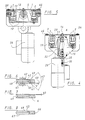
- the horizontal conveyor 1, of which only a short section is shown in Figures 1 and 2 has two endless circulating belts 2 and 3, the upper Trumms are visible in Figure 1 and a horizontal, constantly moving in the direction of arrow 4 pad for there resting Pallets, for example, the pallets 5, 6 and 7 form.
- the pallets are stowable, that is to each pallet, which lies on the straps 2, 3, the subsequent succeed behind and push the front in front of him.
- the pallets 5, 6 and 7 are rectangular, stable plates with double-sided edge rails 8 to 11, which extend in each case over the entire pallet length in the conveying direction according to arrow 4.
- Each pallet has in its longitudinal center 12, at its deliberatelyaufissertigen end, an outstanding on the underside designed as a guide roller driver 13, 14.
- These drivers fit into the guide groove 16 ei ner roller 17 which is rotatably mounted in bearings 37, 38 with its axis 18 in the conveying direction, ie horizontally, under the middle between the straps 2 and 3, which coincides with the longitudinal center 12.
- the bearing 37 is arranged in a lock housing 19 and the bearing 38 in a changer housing 15.
- the two housings 15 and 19 are attached to continuous profile bars of the horizontal conveyor 1.
- a drive motor 20 which drives a cam plate 21 and a coaxial and torsionally secure to the motor output shaft plugged V-belt pulley 22.
- This V-belt pulley drives in a ratio of 1: 2, the V-belt pulley 23, which lies on the roller shaft 24.
- the cam disc 21 has a cam 25, on the other hand, a switch 26 is located, which switches off the drive motor 20 at juxtaposition of the switch to the cam 25.
- a control device not shown, of the horizontal conveyor, performs the cam 21 a full revolution and the roller 17 two full revolutions.
- the roller is drawn at a standstill.
- the guide groove 16 has two full courses.
- the guide groove 16 has at its two ends depending on a circumferentially extending groove portion 29, 30 which is open via an axial inlet portion 32 and an axial outlet portion 31 at the respective end face 33, 34, namely the section 31 with a Austriebskurve 70th ,
- the two groove sections 29 and 30 each form a stop 35, 36.
- the stop 35 fixes the pallet 5 in the machining position and the stop 36 fixes the pallet 6, which is the next in the row of subsequent pallets, in the ready position.
- the two nu tenabête 29, 30 and the two stops 35, 36 extend over the common circumferential angle 39, which thus determines the tolerance for a functional standstill position of the roller 17. This corresponds to the circumferential extent of the cam 25th
- edge rails 8, 9, 10 and 11 of the pallets are, as can be seen particularly well from Figure 6, roof-shaped, with flattened tip outwardly projecting edge ribs, which are formed by two wedge surfaces 40, 41 and an end face 42.
- the wedge surfaces are at an angle 43 to each other and the end face 42 is perpendicular to the support plane defined by the straps 2 and 3 and symmetrical to the wedge surfaces 40, 41.
- the angle 43 is preferably slightly less than ninety degrees.
- the wedge surfaces and the end face extend mirror-symmetrically on both sides over the entire pallet length and are the same for all pallets.
- rollers 45 to 54 To these edge rails fit wedge-shaped circumferential grooves, for example, the circumferential groove 44, of about vertical axes 55, 56 ... rotatably mounted on the housing 19 rollers 45 to 54. These rollers are fixedly mounted on the housing 19, that is, the bearings of the rollers are firmly mounted in the three orthogonal spatial directions. They are rotatable about axes perpendicular to the drawing plane of FIG. 1.
- the rollers 48 to 53 are on the processing position, which occupies the pallet 5, distributed and compared to the altitude, which occupies the resting on the straps 2 and 3 pallet 6, raised by 0.8 mm and arranged so that the located in the processing position Pallet 5 fits snug fit between the rollers 48 to 53 fits.
- the pallet 5 is lifted slightly in this way in their processing position of the straps 2 and 3, so that they no longer touch with the straps and straps no longer grind on this pallet.
- the pallet is orthogonal adjusted in its operating position by the rollers 48 to 53 and fixed in connection with the stop 35 in this machining position.
- the rollers 49 and 54 are at the downstream end of the machining position, which occupies the pallet 6, and have, as seen in Figure 7, a slightly wider circumferential groove, so that for the pallet 6 a small game 60 remains in the vertical direction.
- the pallet 6 In the ready position, the pallet 6 is at the lower end of the game 60 and is for the entry into the processing position otherwise orthogonally preoriented, as shown in Figure 7.
- the pallet 6 When entering the machining position, the pallet 6 is lifted by the rollers 47, 48, 52 and 53 into the machining position and the play 60 allows the height compensation necessary for the pallet entering the machining position.
- the rollers 47, 48, 52, 53 are arranged for lifting the incoming into the processing position pallet in pairs closely adjacent to each other at the very end of the delivery position.
- the height compensation can also be achieved according to a modification in that the rollers 49 and 54 are formed exactly like the other roles, so not with game in the circumferential groove, but on its axis between two end positions defined by stops 61, 62 are movable up and down to an extent as it corresponds to the game 60. These stops are shown in dashed lines in Figure 6 for the sake of simplicity, although they do not belong to the drawn there roller 48, but in this modification to the roller 49 and 54th
- non-rotatable wedge elements may be provided instead of the rollers, along which the edge ribs of the pallets slide along. It then arises, as far as the function is concerned, the same cross-sectional image as in Figure 6 and 7 drawn.
- the operation of the device of Figures 1-7 is the following:
- the pallet change from the position shown in FIG. 1, in which workpieces arranged or mounted on the pallet 5, which are not shown, are processed, is triggered by an external signal from a control device which switches on the motor 20.
- By starting the rotation of the roller gets the driver 13 of the pallet 5 located in the machining position in the axial outlet section 31, receives a push through the ejection curve 70, leaves the guide groove 16 and at the same time the driver 14 of the pallet 6 in the ready position is in the first gear 28 of the guide groove, so that this palette is advanced in the conveying direction 4.
- This feed takes place in accordance with the high speed of the motor 20 at a much higher conveying speed in the direction of arrow 4 than the feed by the slowly circulating belts 2, 3rd
- the pallet 6 is driven in about 0.4 sec. (Seconds) by the roller 17 in the position of the pallet 5 and pushes the pallet 5 in front of him, which then then lowered onto the straps 2, 3 and further promoted by these becomes.
- the webbings would instead of the 0.4 sec. 12.0 sec. Needed to carry the pallet 6 in the processing position.
- the pallet 6 has been lifted on its way to the processing position of the first rollers 48, 53 at the front end and then swung up by the rollers 47, 52 at the rear end and then runs, detached from the straps 2, 3, by the rollers 45, 46, 50, 51 in the drawn for the pallet 5 processing position.
- the feed to the pallet change with much higher speed than the rotational speed of the straps 2 and 3 can be carried out.
- the pallets are fixed in their machining position automatically, solidly, precisely in a predetermined, orthogonally aligned position. It is also noteworthy that for the entire change process, only a single element must be actively adjusted by a drive, namely the roller 17. For the stops no special adjusting members are required because they are integrated into the roller and for lifting and fixing the in processing position pallet located next to their leadership function, the rollers 45 to 54, which need not be specially driven.
Abstract
Description
Die Erfindung betrifft eine Vorrichtung zum Arretieren einer auf den Förderelementen eines Horizontalförderers aufliegend angelieferten, je beidseitig sich in Förderrichtung erstreckende gerade Randschienen aufweisenden Palette in einer Bearbeitungsposition, angehoben von den Förderelementen des Förderers, mit Hilfe eines in die Förderbahn aufstaubarer Paletten stellbaren Anschlages.The invention relates to a device for locking a lying on the conveyor elements of a horizontal conveyor delivered, depending on both sides extending in the conveying direction straight edge rails pallet in a processing position, lifted by the conveyor elements of the conveyor, adjustable by means of a stowable in the conveyor pallets stop.
Bei einer bekannten Vorrichtung dieser Art stößt die in Bearbeitungsposition gelangende Palette gegen einen Anschlag und wird dann von seitlich angesetzten Greifern erfaßt und in einer leicht angehobenen Bearbeitungsposition fixiert.In a known device of this kind, the reaching into the processing position pallet abuts against a stop and is then detected by laterally attached grippers and fixed in a slightly raised processing position.
Aufgabe der Erfindung ist es, diese Vorrichtung zu vereinfachen.The object of the invention is to simplify this device.
Die Erfindung ist dadurch gekennzeichnet, daß beide Randschienen je zwei einen zur Seite offenen Keilwinkel bildende, sich über die ganze Randschienenlänge erstreckende Keilflächen aufweisen, die mit da hinein formschlüssig passenden Keilelementen zusammenwirken und daß Keilelemente beidseitig entlang der Förderbahn der Keilflächen über die Bearbeitungsposition verteilt, aufgereiht und ortsfest befestigt sind.The invention is characterized in that both edge rails each have two forming an open to the side wedge angle, extending over the entire edge rail length wedge surfaces which cooperate with there form-fitting matching wedge elements and that wedge elements distributed on both sides along the conveyor track of the wedge surfaces on the processing position, lined up and fixed in place.
Während bei der bekannten Vorrichtung die zum Fixieren der Palette vorgesehenen Greifer aktiv bewegt werden müssen, müssen die zu dem gleichen Zweck vorgesehenen Keilelemente aktiv nicht bewegt werden, sie werden allenfalls von der betreffenden Palette bewegt.While in the known device the grippers provided for fixing the pallet must be actively moved, the wedge elements provided for the same purpose do not have to be actively moved; at most they are moved by the respective pallet.
Allein dadurch ist eine beträchtliche Vereinfachung der kon struktiven Ausgestaltung möglich, die auch eine Verbesserung der Betriebssicherheit zur Folge hat.This alone is a considerable simplification of the kon structural design possible, which also has an improvement in operational safety result.
Man kann die Keilelemente auch leicht so ausbilden, daß sie die in Bearbeitungsposition geratende Palette von den Gurtbändern abheben und damit schleifenden Kontakt der weiter umlaufenden Gurtbänder beim Bearbeiten der Palette beziehungsweise der Auflage der Palette vermeiden. Eine entsprechende Weiterbildung, die dies ermöglicht, ist dadurch gekennzeichnet, daß ein oder mehrere Keilelemente beidseitig am förderabwärtigen Ende einer in Bereitstellungsposition befindlichen Palette angeordnet sind, daß die Höhenlage dieser der Bereitstellungsposition zugeordneten Keilelemente jeder Seite der Höhenlage einer auf den Gurtbändern liegenden Palette entspricht und daß die Höhenlage der folgenden, der Bearbeitungsposition zugeordneten Keilelemente der Höhenlage einer von den Gurtbändern um einen zur Entkupplung hinreichenden kleinen Betrag von 0,3 bis 10 mm (Millimeter), vorzugsweise 0,8 mm abgehobenen Palette entspricht.It is also easy to form the wedge elements so that they lift the range in processing position range of the straps and thus avoid sliding contact the wider circumferential straps when editing the pallet or the support of the pallet. A corresponding development, which makes this possible, is characterized in that one or more wedge elements are arranged on both sides at the downstream end of a pallet in the stowed position, that the altitude of the supply position associated wedge elements each side corresponds to the altitude of lying on the straps pallet and that the altitude of the following, the processing position associated wedge elements of the altitude corresponds to one of the straps to a sufficient for decoupling small amount of 0.3 to 10 mm (millimeters), preferably 0.8 mm lifted pallet.
Die der Bereitstellungsposition zugeordneten Keilelemente justieren in wünschenswerter Weise das vorauslaufende Ende der in Bereitstellungsposition befindlichen Palette und erleichtern so den Einlauf dieser Palette in die der Bearbeitungsposition zugeordneten Keilelemente. Für den notwendigen Höhenausgleich trifft man zweckmäßigerweise Maßnahmen an den der Bereitstellungsposition zugeordenten Keilelementen. Das kann beispielsweise dadurch geschehen, daß die Keilform der der Bereitstellungsposition zugeordneten Keilelemente das für den Höhenausgleich nötige Spiel bieten oder dadurch, daß die der Bereitstellungsposition zugeordneten Keilelemente zum Höhenausgleich zwischen zwei Endstellungen höhenverstellbar sind.The wedge members associated with the stowage position desirably adjust the leading end of the pallet in the stowed position to facilitate the infeed of that pallet to the wedge members associated with the processing position. For the necessary height compensation, it is expedient to take measures at the wedge elements associated with the provisioning position. This can be done, for example, that the wedge shape of the supply position associated wedge elements provide the necessary for height compensation game or the fact that the supply position associated wedge elements for height compensation between two end positions are adjustable in height.
Die der Bearbeitungsposition zugeordneten Keilelemente wer den zweckmäßig im Interesse einer soliden Fixierung der Palette, bezogen auf alle räumlichen Richtungen, ortsfest befestigt.The wedge elements associated with the processing position the appropriate fixed in the interest of a solid fixation of the range, based on all spatial directions, fixed.
Zum Erleichtern des Anhebens des rückwärtigen Endes einer in die Bearbeitungsposition einlaufenden Palette sind vorzugsweise beidseitig je zwei Keilelemente dicht am förderaufwärtigen Ende der Bearbeitungsposition und dicht nebeneinander angeordnet.For facilitating the lifting of the rear end of a running into the processing position pallet are preferably on both sides two wedge elements each close to the upstream end of the processing position and arranged close to each other.
Die Keilelemente können Gleiter sein, vorzugsweise werden aber Rollen eingesetzt, um Gleitwiderstand zu vermeiden. Eine dementsprechende Ausgestaltung, die bevorzugt ist, ist dadurch gekennzeichnet, daß die Keilflächen eine dachförmige, mit abgeflachter Spitze nach außen ragende Randrippe bilden und daß die Keilelemente um vertikale Achsen drehbar gelagerte Rollen sind, die je eine keilförmige Umfangsnut aufweisen.The wedge elements may be sliders, but preferably rollers are used to prevent sliding resistance. A corresponding embodiment, which is preferred, is characterized in that the wedge surfaces form a roof-shaped, with flattened tip outwardly projecting edge rib and that the wedge elements are rotatable about vertical axes rollers, each having a wedge-shaped circumferential groove.
Eine weitere Aufgabe der Erfindung ist es, bei einer Vorrichtung der eingangs genannten Art die Wechselgeschwindigkeit zu erhöhen. Diese Aufgabe wird dadurch gelöst, daß ein auf die in Bereitstellungsposition befindliche Palette einwirkendes Förderelement zum Fördern dieser Palette beim Palettenwechsel in die Bearbeitungsposition vorgesehen ist, und zwar mit einer Geschwindigkeit, die wesentlich höher ist als die Fördergeschwindigkeit des Doppelgurtes.Another object of the invention is to increase the speed of change in a device of the type mentioned. This object is achieved in that a conveyor element acting on the pallet in the stowed position is provided for conveying this pallet during the pallet change to the processing position, with a speed which is substantially higher than the conveying speed of the double belt.
Die Erfindung macht sich dabei den Umstand zunutze, daß die Paletten auf dem Doppelgurt rutschen können, wie sie es in Bereitstellung bei dem bekannten Palettenwechsler auch tun, also auch schneller auf dem Doppelgurt vorausgeschoben werden können als der Umlaufgeschwindigkeit des Doppelgurtes entspricht.The invention makes use of the fact that the pallets can slide on the double belt, as they do in provision in the known pallet changer, so also can be pushed faster on the double belt than the rotational speed of the double belt corresponds.
Die beiden bei der bekannten Vorrichtung vorgesehenen, der Bereitstellungsposition und in der Bearbeitungsposition zugeordneten Anschläge, die auch nach der Erfindung erforderlich sind, werden vorteilhaft konstruktiv in das Förderelement integriert, so daß man anstatt zwei beweglicher Anschläge wie beim Stande der Technik nur ein einziges bewegliches Förderelement antreiben muß. Die entsprechende Weiterbildung ist dadurch gekennzeichnet, daß das Förderelement die beiden Anschläge aufweist und bei Beginn der Förderbewegung des Förderelementes außer Funktion stellt und bei Ende der Förderbewegung wieder in Funktion stellt.The two provided in the known device, the staging position and in the processing position associated stops, which are also required according to the invention are advantageously structurally integrated into the conveyor element, so that instead of two movable stops as in the prior art, only a single movable conveyor element must drive. The corresponding development is characterized in that the conveying element has the two stops and at the beginning of the conveying movement of the conveying element is inoperative and at the end of the conveying movement back into operation.
Eine bevorzugte Ausgestaltung eines solchen Förderelementes, die sich durch besonders einfachen konstruktiven Aufbau und exakte Positionierbarkeit der Anschläge und damit der Bereitstellungsposition und insbesondere der Bearbeitungsposition auszeichnet, ist dadurch gekennzeichnet, daß das Förderelement eine Walze ist, die um eine Achse parallel zur Förderrichtung drehbar gelagert ist, und auf ihrem Umfang eine mit einem an der Palette angeordneten Führungselement zusammenwirkende Führungswendel aufweist, die sich vom Anschlag für die Bereitstellungsposition bis zum Anschlag für die Bearbeitungsposition erstreckt und 1 bis 5, vorzugsweise 2 Gänge aufweist.A preferred embodiment of such a conveying element, which is characterized by a particularly simple structural design and exact positioning of the stops and thus the ready position and in particular the processing position, characterized in that the conveying element is a roller which is rotatably mounted about an axis parallel to the conveying direction , And on its periphery a cooperating with a arranged on the pallet guide member guide coil which extends from the stop for the supply position to the stop for the processing position and 1 to 5, preferably 2 courses.
Dabei empfiehlt es sich, daß die Walze mit ihrer Achse senkrecht zur Mittellinie des Doppelgurtes gelagert ist, daß die Führungswendel eine Führungsnut ist, daß die Führungsnut an beiden Enden einen den betreffenden Anschlag bildenden, sich in Umfangsrichtung erstreckenden Nutenabschnitt aufweist und offen ist, daß die beiden Nutenabschnitte sich über den gleichen Umfangswinkel erstrecken, daß in die Führungsnut ein vorzugsweise als Führungsrolle ausgebildetes Führungselement paßt, das unten an der Längsmitte einer jeden Palette gelagert ist.It is recommended that the roller is mounted with its axis perpendicular to the center line of the double belt, that the guide coil is a guide, that the guide groove at both ends has a respective stop forming, extending in the circumferential direction groove portion and is open, that the two groove portions extend over the same circumferential angle, that in the guide groove a preferably designed as a guide roller guide element fits, which is mounted below at the longitudinal center of each pallet.
Für einen reibungslosen Wechselvorgang ist es wichtig, daß die in Bearbeitungsposition befindliche Palette möglichst schnell abgefördert wird. Dazu sollte sie möglichst schnell ihre Trägheit überwinden und die Geschwindigkeit des Doppelgurtes aufnehmen. Das kann man unterstützen, indem dieser Palette bei Beginn des Wechselvorganges von dem Förderelement ein Schubs verliehen wird. Das ist sehr einfach dadurch erzielbar, daß der der Bearbeitungsposition zugeordnete Nutenabschnitt in einen achsparallel gerichteten Auslaufabschnitt mündet mit einer Austriebskurve an der Rückwand.For a smooth change process, it is important that the located in processing position pallet is carried away as quickly as possible. For this she should overcome her inertia as quickly as possible and record the speed of the double belt. This can be supported by giving this pallet a push at the beginning of the changing process of the conveyor element. This can be achieved very simply by virtue of the fact that the groove section assigned to the machining position opens into an outlet section directed axially parallel with an ejection curve on the rear wall.
Die Erfindung wird nun anhand der beigefügten Zeichnung näher erläutert.The invention will now be described with reference to the accompanying drawings.
In der Zeichnung zeigt:
Figur 1 einen Palettenwechsler für einen linearen Horizontalförderer von oben gesehen, teilweise aufgeschnitten,Figur 2 den Teilschnitt II ausFigur 1,Figur 3 die Walze ausFigur 1 von oben gesehen mit den Führungselementen der zugehörigen Paletten,- Figur 4 den Schnitt IV aus
Figur 2, Figur 5 den Schnitt V ausFigur 2,Figur 6 eine Einzelheit gemäß dem Teilschnitt VI ausFigur 1,Figur 7 eine Einzelheit gemäß dem Teilschnitt VII ausFigur 1 undFigur 8 in der Darstellung entsprechendFigur 6 eine Abänderung des inFigur 1 bis 7 dargestellten Ausführungsbeispiels.
- 1 shows a pallet changer for a linear horizontal conveyor seen from above, partially cut away,
- FIG. 2 shows the partial section II from FIG. 1,
- FIG. 3 shows the roller from FIG. 1 seen from above with the guide elements of the associated pallets,
- FIG. 4 shows the section IV from FIG. 2,
- FIG. 5 shows the section V from FIG. 2,
- 6 shows a detail according to the partial section VI of Figure 1,
- Figure 7 shows a detail according to the partial section VII of Figure 1 and
- Figure 8 in the illustration corresponding to Figure 6 is a modification of the embodiment shown in Figure 1 to 7.
Der Horizontalförderer 1, von dem in Figur 1 und 2 nur ein kurzer Abschnitt dargestellt ist, weist zwei endlos umlaufende Gurtbänder 2 und 3 auf, deren obere Trumms in Figur 1 sichtbar sind und die eine horizontale, ständig in Pfeilrichtung 4 fortbewegte Unterlage für dort aufliegende Paletten, zum Beispiel die Paletten 5, 6 und 7 bilden. Die Paletten sind aufstaubar, das heißt an jede Palette, die auf den Gurtbändern 2, 3 liegt, kann die nachfolgende hinten anstoßen und die vordere vor sich herschieben.The
Die Paletten 5, 6 und 7 sind rechteckige, stabile Platten mit beidseitig Randschienen 8 bis 11, die sich jeweils über die ganze Palettenlänge in Förderrichtung gemäß Pfeil 4 erstrecken. Jede Palette weist in ihrer Längsmitte 12, und zwar an ihrem förderaufwärtigen Ende, einen an der Unterseite herausragenden als Führungsrolle ausgebildete Mitnehmer 13, 14 auf. Diese Mitnehmer passen in die Führungsnut 16 ei ner Walze 17, die mit ihrer Achse 18 in Förderrichtung, also horizontal, unter der Mitte zwischen den Gurtbändern 2 und 3, die mit der Längsmitte 12 zusammenfällt, drehbar in Lagern 37, 38 gelagert ist. Das Lager 37 ist in einem Arretierergehäuse 19 und das Lager 38 in einem Wechslergehäuse 15 angeordnet. Die beiden Gehäuse 15 und 19 sind an durchgehenden Profilstangen des Horizontalförderers 1 befestigt.The
Zum Antrieb der Walze dient ein Antriebsmotor 20, der eine Nockenscheibe 21 und eine koaxial und verdrehungssicher dazu auf die Motorabtriebswelle aufgesteckte Keilriemenscheibe 22 treibt. Diese Keilriemenscheibe treibt im Übersetzungsverhältnis 1 : 2 die Keilriemenscheibe 23, die auf der Walzenwelle 24 steckt. Die Nockenscheibe 21 weist einen Nocken 25 auf, demgegenüber ein Schalter 26 steht, der bei Gegenüberstellung des Schalters zum Nocken 25 den Antriebsmotor 20 abschaltet. Bei der nächsten Wiedereinschaltung des Antriebsmotors, die von einer nicht dargestellten Steuervorrichtung des Horizontalförderers ausgelöst wird, vollführt die Nockenscheibe 21 eine volle Umdrehung und die Walze 17 zwei volle Umdrehungen.To drive the roller is a
In allen Zeichnungen ist die Walze im Stillstand gezeichnet. Die Führungsnut 16 weist zwei volle Gänge auf. Die Führungsnut 16 weist an ihren beiden Enden je einen sich in Umfangsrichtung erstreckenden Nutenabschnitt 29, 30 auf, der über einen axialen Einlaufabschnitt 32 und einen axialen Auslaufabschnitt 31 an der betreffenden Stirnseite 33, 34 offen ist, und zwar der Abschnitt 31 mit einer Austriebskurve 70.In all drawings, the roller is drawn at a standstill. The guide groove 16 has two full courses. The guide groove 16 has at its two ends depending on a circumferentially extending
Die beiden Nutenabschnitte 29 und 30 bilden je einen Anschlag 35, 36. Der Anschlag 35 fixiert die Palette 5 in der Bearbeitungsposition und der Anschlag 36 fixiert die Palette 6, das ist die in der Reihe der nachfolgenden Paletten nächstfolgende, in Bereitstellungsposition. Die beiden Nu tenabschnitte 29, 30 und die beiden Anschläge 35, 36 erstrecken sich über den gemeinsamen Umfangswinkel 39, der mithin die Toleranz bestimmt für eine funktionsfähige Stillstandsstellung der Walze 17. Dem entspricht die Umfangsausdehnung des Nocken 25.The two
In der gezeichneten Stillstandsstellung der Walze 17 sind die beiden Paletten 5 und 6 durch die Anschläge 35, 36 präzise, bezogen auf die Förderrichtung, fixiert. Die Palette 6 ruht dabei auf den Gurtbändern 2 und 3, die unter der Palette während des Stillstandes der Palette 6 in der Bereitstellungsposition gleiten. Das gleiche gilt für alle nachfolgenden Paletten, die auf die Palette 6 auflaufen und dadurch ebenfalls stillgesetzt werden.In the illustrated standstill position of the
Die Randschienen 8, 9, 10 und 11 der Paletten sind, wie besonders gut aus Figur 6 ersichtlich, dachförmige, mit abgeflachter Spitze nach außen ragende Randrippen, die durch je zwei Keilflächen 40, 41 und eine Stirnfläche 42 gebildet werden. Die Keilflächen stehen im Winkel 43 zueinander und die Stirnfläche 42 steht senkrecht zu der durch die Gurtbänder 2 und 3 definierten Unterstützungsebene und symmetrisch zu den Keilflächen 40, 41. Der Winkel 43 ist vorzugsweise etwas kleiner als neunzig Grad. Die Keilflächen und die Stirnfläche erstrecken sich über die ganze Palettenlänge spiegelsymmetrisch auf beiden Seiten und sind bei allen Paletten gleich.The edge rails 8, 9, 10 and 11 of the pallets are, as can be seen particularly well from Figure 6, roof-shaped, with flattened tip outwardly projecting edge ribs, which are formed by two
Zu diesen Randschienen passen formschlüssig keilförmige Umfangsnuten, zum Beispiel die Umfangsnut 44, von um vertikale Achsen 55, 56 ... drehbar am Gehäuse 19 gelagerten Rollen 45 bis 54. Diese Rollen sind ortsfest am Gehäuse 19 gelagert, das heißt, die Lager der Rollen sind in den drei orthogonalen räumlichen Richtungen fest montiert. Sie sind drehbar um Achsen senkrecht zur Zeichenebene der Figur 1.To these edge rails fit wedge-shaped circumferential grooves, for example, the
Die Rollen 48 bis 53 sind auf die Bearbeitungsposition, die die Palette 5 einnimmt, verteilt und gegenüber der Höhenlage, die die auf den Gurtbändern 2 und 3 aufliegende Palette 6 einnimmt, um 0,8 mm angehoben und so angeordnet, daß die in Bearbeitungsposition befindliche Palette 5 formschlüssig stramm passend zwischen die Rollen 48 bis 53 paßt. Die Palette 5 ist auf diese Weise in ihrer Bearbeitungsposition etwas von den Gurtbändern 2 und 3 abgehoben, so daß sie keine Berührung mehr hat mit den Gurtbändern und die Gurtbänder nicht mehr an dieser Palette schleifen. Außerdem ist die Palette orthogonal in ihrer Betriebsstellung durch die Rollen 48 bis 53 justiert und in Verbindung mit dem Anschlag 35 in dieser Bearbeitungsstellung fixiert.The
Die Rollen 49 und 54 sind am förderabwärtigen Ende der Bearbeitungsposition, die die Palette 6 einnimmt, angeordnet und haben, wie aus Figur 7 ersichtlich, eine etwas weitere Umfangsnut, so daß für die Palette 6 ein kleines Spiel 60 in Höhenrichtung verbleibt. In der Bereitstellungsposition liegt die Palette 6 am unteren Ende des Spiels 60 und ist dabei für den Einlauf in die Bearbeitungsposition im übrigen orthogonal vororientiert, wie in Figur 7 gezeichnet. Beim Einlauf in die Bearbeitungsposition wird die Palette 6 von den Rollen 47, 48, 52 und 53 in die Bearbeitungsposition angehoben und das Spiel 60 gestattet den für die in die Bearbeitungsposition einlaufende Palette erforderlichen Höhenausgleich. Die Rollen 47, 48, 52, 53 sind für das Anheben der in die Bearbeitungsposition einlaufenden Palette paarweise dicht nebeneinander ganz am förderaufwärtigen Ende der Bereitstellungsposition angeordnet.The
Der Höhenausgleich kann gemäß einer Abänderung auch dadurch erzielt werden, daß die Rollen 49 und 54 exakt genauso ausgebildet werden wie die übrigen Rollen, also nicht mit Spiel in der Umfangsnut, aber auf ihrer Achse zwischen zwei durch Anschläge 61, 62 definierten Endstellungen auf und ab beweglich sind in einem Maße, wie es dem Spiel 60 entspricht. Diese Anschläge sind der Einfachheit halber in Figur 6 gestrichelt eingezeichnet, obwohl sie nicht zu der dort gezeichneten Rolle 48 gehören, sondern in dieser Abänderung zur Rolle 49 und 54.The height compensation can also be achieved according to a modification in that the
In einer weiteren Abänderung können statt der Rollen auch nicht drehbare Keilelemente vorgesehen sein, an denen die Randrippen der Paletten entlanggleiten. Es ergibt sich dann, soweit es die Funktion angeht, das gleiche Querschnittsbild wie in Figur 6 und 7 gezeichnet.In a further modification, non-rotatable wedge elements may be provided instead of the rollers, along which the edge ribs of the pallets slide along. It then arises, as far as the function is concerned, the same cross-sectional image as in Figure 6 and 7 drawn.
Nach einer weiteren Abänderung ist es auch möglich, die Keilform umzukehren, das heißt anstelle einer Randrippe wie für die Palette 66 in Figur 8 dargestellt eine Außennut 65 vorzusehen und entsprechend für die Rollen, wie für die Rolle 67 gezeichnet, eine Umfangsrippe 68 vorzusehen. Die Winkelanordnungen und der formschlüssige Eingriff ist dann entsprechend wie im Text zu Figur 6 und 7 erläutert und auch der Höhenausgleich kann entsprechend erfolgen. Auch statt der Rolle 67 kann man einen entsprechend geformten Gleiter vorsehen.After a further modification, it is also possible to reverse the wedge shape, that is, instead of an edge rib as shown for the
Die Wirkungsweise der Vorrichtung aus Figur 1 - 7 ist folgende:
Der Palettenwechsel aus der in Figur 1 dargestellten Position, in der auf der Palette 5 angeordnete oder montierte Werkstücke, die nicht dargestellt sind, bearbeitet werden, wird ausgelöst durch ein äußeres Signal von einer Steuervorrichtung, die den Motor 20 einschaltet. Das führt zu zwei vollen Umdrehungen der Walze 17, die im Anschluß daran wieder in der gezeichneten Stellung stillgesetzt wird. Durch Beginn der Drehbewegung der Walze gerät der Mitnehmer 13 der in Bearbeitungsposition befindlichen Palette 5 in den axialen Auslaufabschnitt 31, erhält dabei durch die Austriebskurve 70 einen Schubs, verläßt die Führungsnut 16 und gleichzeitig gerät der Mitnehmer 14 der in Bereitstellungsposition befindlichen Palette 6 in den ersten Gang 28 der Führungsnut, so daß diese Palette in Förderrichtung 4 vorgeschoben wird. Dieser Vorschub erfolgt entsprechend der hohen Drehzahl des Motors 20 mit wesentlich höherer Fördergeschwindigkeit in Pfeilrichtung 4 als der Vorschub durch die langsam umlaufenden Gurtbänder 2, 3.The operation of the device of Figures 1-7 is the following:
The pallet change from the position shown in FIG. 1, in which workpieces arranged or mounted on the
Die Palette 6 wird in etwa 0,4 sec. (Sekunden) durch die Walze 17 in die Position der Palette 5 getrieben und schiebt dabei die Palette 5 vor sich her, die sich dann anschließend auf die Gurtbänder 2, 3 absenkt und von diesen weitergefördert wird. Die Gurtbänder hätten statt der 0,4 sec. 12,0 sec. benötigt, die Palette 6 in die Bearbeitungsposition zu tragen.The
Der Vorschub der Palette 6 ist beendet, sobald der Mitnehmer 14 in die Position, in der der Mitnehmer 13 in Figur 1 gezeichnet ist, einnimmt.The feed of the
In Endstellung der Walze 17 oder kurz davor findet der Mitnehmer der nächstfolgenden Palette 7 Eingang in den axialen Abschnitt 32 bis zum Anschlag 36 und gelangt in die Stellung, in der der Mitnehmer 14 in Figur 1 gezeichnet ist. Die Folge ist, daß die Palette 7 sich nun in Bereitstellungsposition befindet. Alle nachfolgenden Paletten stoßen durch die Schubwirkung der Gurtbänder aneinander und rutschen beim Vorschub der Palette 7 um eine Palettenposition nach. Im Anschluß daran liegen sie, wie auch die in Bereitstellungsposition befindliche Palette 7, auf den darunter rutschenden Gurtbändern 2, 3.In the end position of the
Die Palette 6 ist auf ihrem Wege in die Bearbeitungsposition zunächst von den Rollen 48, 53 am vorderen Ende angehoben worden und dann von den Rollen 47, 52 am hinteren Ende hochgeschwenkt worden und läuft dann, losgelöst von den Gurtbändern 2, 3, durch die Rollen 45, 46, 50, 51 in die für die Palette 5 gezeichnete Bearbeitungsposition hinein.The
Bemerkenswert ist, daß der Vorschub zum Palettenwechsel mit vielfach höherer Geschwindigkeit als der Umlaufgeschwindigkeit der Gurtbänder 2 und 3 entspricht erfolgen kann. Bemerkenswert ist weiter, daß die Paletten in ihrer Bearbeitungsposition selbsttätig, solide, präzis in einer vorgegebenen, orthogonal ausgerichteten Position fixiert sind. Bemerkenswert ist weiterhin, daß für den ganzen Wechselvorgang nur ein einziges Element aktiv durch einen Antrieb verstellt werden muß, nämlich die Walze 17. Für die Anschläge sind keine besonderen Verstellorgane erforderlich, weil sie in die Walze integriert sind und zum Anheben und Fixieren der in Bearbeitungsposition befindlichen Palette dienen neben ihrer Führungsfunktion die Rollen 45 bis 54, die nicht besonders angetrieben werden müssen.It is noteworthy that the feed to the pallet change with much higher speed than the rotational speed of the
Claims (10)
daß beide Randschienen ( 8, 9 ) je zwei einen zur Seite offenen Keilwinkel ( 43 ) bildende, sich über die ganze Randschienenlänge erstreckende Keilflächen (40, 41) aufweisen, die mit da hinein formschlüssig passenden Keilelementen (45 - 54) zusammenwirken und
daß Keilelemente beidseitig entlang der Förderbahn der Keilflächen über die Bearbeitungsposition verteilt, aufgereiht und ortsfest befestigt sind.1. A device for locking a lying on the conveyor elements of a horizontal conveyor delivered, depending on both sides extending in the conveying direction straight edge rails pallet in a processing position, lifted by the conveyor elements of the conveyor, with the aid of a stowable in the conveyor pallets adjustable stop, characterized
in that each of the two edge rails (8, 9) has two wedge surfaces (40, 41) which extend over the entire edge rail length and which cooperate with wedge elements (45-54) which fit therewith in a form-locking manner
that wedge elements distributed on both sides along the conveying path of the wedge surfaces over the processing position, lined up and fixed in place.
daß ein oder mehrere Keilelemente (49, 54) beidseitig am förderabwärtigen Ende einer in Bereitstellungsposition befindlichen Palette ( 6 ) angeordnet sind,
daß die Höhenlage dieser der Bereitstellungsposition zugeordneten Keilelemente jeder Seite der Höhenlage einer auf den Gurtbändern ( 2, 3 ) liegenden Palette ( 6, 7 ) entspricht und
daß die Höhenlage der folgenden, der Bearbeitungsposition zugeordneten Keilelemente (45 - 53) der Höhenlage einer von den Gurtbändern um einen zur Entkupplung hinreichenden kleinen Betrag von 0,3 bis 10 mm (Millimeter), vorzugsweise 0,8 mm abgehobenen Palette entspricht.2. Apparatus according to claim 1, characterized in that
in that one or more wedge elements (49, 54) are arranged on both sides at the downstream end of a pallet (6) located in the supply position,
that the height position of these wedge elements assigned to the provisioning position corresponds on each side to the height position of a pallet (6, 7) lying on the straps (2, 3) and
that the height position of the following, the processing position associated wedge elements (45 - 53) corresponds to the height of one of the straps to a sufficient for decoupling small amount of 0.3 to 10 mm (millimeters), preferably 0.8 mm lifted pallet.
daß die Keilform der der Bereitstellungsposition zugeordneten Keilelemente (49, 54) das für den Höhenausgleich nöti ge Spiel ( 60 ) bieten.3. Device according to claim 2, characterized
in that the wedge shape of the wedge elements (49, 54) assigned to the provisioning position necessitates the height compensation ge game (60).
daß die der Bereitstellungsposition zugeordneten Keilelemente zum Höhenausgleich zwischen zwei Endstellungen (61, 62) höhenverstellbar sind.4. Apparatus according to claim 2, characterized in that
in that the wedge elements assigned to the provisioning position are height-adjustable for height compensation between two end positions (61, 62).
daß beidseitig je zwei Keilelemente (47, 48, 52, 53) dicht am förderaufwärtigen Ende der Bearbeitungsposition und dicht nebeneinander angeordnet sind.5. Device according to one of the preceding claims, characterized
that on both sides two wedge elements (47, 48, 52, 53) are arranged close to the upstream end of the processing position and close together.
daß die Keilflächen (40, 41) eine dachförmige, mit abgeflachter Spitze nach außen ragende Randrippe ( 9 ) bilden und
daß die Keilelemente (45 - 54) um vertikale Achsen (55, 56) drehbar gelagerte Rollen sind, die je eine keilförmige Umfangsnut ( 44 ) aufweisen.6. Device according to one of the preceding claims, characterized
that the wedge surfaces (40, 41) form a roof-shaped, with flattened tip outwardly projecting edge rib (9) and
in that the wedge elements (45-54) are rollers which are mounted rotatably about vertical axes (55, 56) and each have a wedge-shaped circumferential groove (44).
daß ein Doppelgurt ( 2, 3 ) als Förderunterlage vorgesehen ist,
daß ein in Funktion und außer Funktion stellbarer Anschlag ( 36 ) für die jeweils nächste in Bearbeitungsposition zu fördernde Palette ( 6 ) einer Bereitstellungsposition zugeordnet ist und
daß ein auf die in Bereitstellungsposition befindliche Palette ( 6 ) einwirkendes Förderelement ( 17 ) zum Fördern dieser Palette beim Palettenwechsel in die Bearbeitungsposition ( 5 ) vorgesehen ist, und zwar mit einer Geschwindigkeit, die wesentlich höher ist als die Förderge schwindigkeit des Doppelgurtes ( 2, 3 ).7. Device according to one of the preceding claims, characterized
that a double belt (2, 3) is provided as a conveyor pad,
in that a stop (36) adjustable in function and out of operation for the respective next pallet (6) to be conveyed in the machining position is assigned to a provisioning position and
in that a conveyor element (17) acting on the pallet (6) in the ready position is provided for conveying this pallet during the pallet change into the processing position (5) at a speed which is substantially higher than the conveyor speed speed of the double belt (2, 3).
daß das Förderelement ( 17 ) eine Walze ist, die um eine Achse ( 18 ) parallel zur Förderrichtung ( 4 ) drehbar gelagert ist, und auf ihrem Umfang eine mit einem an der Palette ( 5, 6 ) angeordneten Führungselement (17, 14) zusammenwirkenden Führungswendel ( 16 ) aufweist, die sich vom Anschlag ( 36 ) für die Bereitstellungsposition ( 6 ) bis zum Anschlag ( 35 ) für die Bearbeitungsposition ( 5 ) erstreckt und 1 bis 5, vorzugsweise 2 Gänge (27, 28) aufweist.8. Apparatus according to claim 7, characterized in that
that the conveying element (17) is a roller which is rotatably mounted about an axis (18) parallel to the conveying direction (4), and on its periphery cooperating with a guide element (17, 14) arranged on the pallet (5, 6) Guiding coil (16) extending from the stop (36) for the supply position (6) to the stop (35) for the processing position (5) and 1 to 5, preferably 2 courses (27, 28).
daß die Walze ( 17 ) mit ihrer Achse ( 18 ) senkrecht zur Mittellinie ( 12 ) des Doppelgurtes ( 2, 3 ) gelagert ist,
daß die Führungswendel eine Führungsnut ( 16 ) ist,
daß die Führungsnut an beiden Enden einen den betreffenden Anschlag (35, 36) bildenden, sich in Umfangsrichtung erstreckenden Nutenabschnitt (29, 30) aufweist und offen ist,
daß die beiden Nutenabschnitte sich über den gleichen Umfangswinkel ( 39 ) erstrecken,
daß in die Führungsnut ein vorzugsweise als Führungsrolle (13, 14) ausgebildetes Führungselement paßt, das unten an der Längsmitte einer jeden Palette ( 5, 6 ) gelagert ist.9. Apparatus according to claim 7 and 8, characterized in that
the roller (17) is mounted with its axis (18) perpendicular to the center line (12) of the double belt (2, 3),
that the guide helix is a guide groove (16),
in that the guide groove has at both ends a circumferentially extending groove section (29, 30) forming the respective stop (35, 36) and is open,
the two groove sections extend over the same circumferential angle (39),
that in the guide groove a preferably as a guide roller (13, 14) formed guide element which is mounted at the bottom of the longitudinal center of each pallet (5, 6).
daß ein Antriebsmotor (20 ) für die Walze ( 17 ) eine Nockenscheibe ( 21 ) antreibt mit einem Untersetzungsverhältnis zwischen Nockenscheibe und Walze entsprechend der Zahl der Gänge (27, 28) der Führungswendel ( 16 ) und
daß der Nockenscheibe ein von einem Nocken ( 25 ) ansteuerbarer Ausschalter ( 26 ) für den Antriebsmotor zugeordnet ist.10. Apparatus according to claim 7, 8 or 9, characterized
a drive motor (20) for the roller (17) drives a cam disc (21) with a reduction ratio between cam disc and roller corresponding to the number of gears (27, 28) of the guide helix (16) and
in that the cam disc is assigned a switch (26) which can be actuated by a cam (25) for the drive motor.
Priority Applications (5)
| Application Number | Priority Date | Filing Date | Title |
|---|---|---|---|
| DE8989119809T DE58903685D1 (en) | 1989-10-25 | 1989-10-25 | DEVICE ON A HORIZONTAL CONVEYOR FOR LOCKING A PALLET. |
| AT89119809T ATE86216T1 (en) | 1989-10-25 | 1989-10-25 | DEVICE ON A HORIZONTAL CONVEYOR FOR LOCKING A PALLET. |
| EP89119809A EP0424563B1 (en) | 1989-10-25 | 1989-10-25 | Horizontal conveyor with an arresting device for a pallet |
| DE8913409U DE8913409U1 (en) | 1989-10-25 | 1989-11-14 | |
| JP2284089A JPH03158314A (en) | 1989-10-25 | 1990-10-22 | Device for transferring solid pallet positioned horizontally |
Applications Claiming Priority (1)
| Application Number | Priority Date | Filing Date | Title |
|---|---|---|---|
| EP89119809A EP0424563B1 (en) | 1989-10-25 | 1989-10-25 | Horizontal conveyor with an arresting device for a pallet |
Publications (2)
| Publication Number | Publication Date |
|---|---|
| EP0424563A1 true EP0424563A1 (en) | 1991-05-02 |
| EP0424563B1 EP0424563B1 (en) | 1993-03-03 |
Family
ID=8202060
Family Applications (1)
| Application Number | Title | Priority Date | Filing Date |
|---|---|---|---|
| EP89119809A Expired - Lifetime EP0424563B1 (en) | 1989-10-25 | 1989-10-25 | Horizontal conveyor with an arresting device for a pallet |
Country Status (4)
| Country | Link |
|---|---|
| EP (1) | EP0424563B1 (en) |
| JP (1) | JPH03158314A (en) |
| AT (1) | ATE86216T1 (en) |
| DE (2) | DE58903685D1 (en) |
Cited By (3)
| Publication number | Priority date | Publication date | Assignee | Title |
|---|---|---|---|---|
| EP0531610A1 (en) * | 1991-09-10 | 1993-03-17 | BARILLA G. e R. F.lli - Società per Azioni | An apparatus for transporting objects, particularly packaged food products, from a product loading station to a product unloading station |
| DE4445748A1 (en) * | 1994-12-21 | 1996-06-27 | Weiss Gmbh Sondermaschinentech | Pallet locking mechanism for linear conveyor in assembly line |
| US6070534A (en) * | 1996-03-02 | 2000-06-06 | Koenig & Bauer-Albert Aktiengesellschaft | Conveying system |
Families Citing this family (7)
| Publication number | Priority date | Publication date | Assignee | Title |
|---|---|---|---|---|
| DE4002414A1 (en) * | 1990-01-27 | 1991-08-01 | Krause Johann A Maschf | METHOD AND DEVICE FOR TRANSPORTING OBJECTS ALONG A PRODUCTION ROAD |
| CH680665A5 (en) * | 1990-05-11 | 1992-10-15 | Menziken Automation | |
| DE4241676C2 (en) * | 1992-12-10 | 1997-07-10 | Fraunhofer Ges Forschung | Interlinking system |
| JPH0661834U (en) * | 1993-02-04 | 1994-09-02 | エフエスイー株式会社 | Acceleration / deceleration mechanism of transport pallet |
| DE4320501C2 (en) * | 1993-06-21 | 1995-09-07 | Sim Zufuehr Und Montagetechnik | System for processing and / or assembling workpieces arranged on a workpiece carrier |
| DE4328983C2 (en) * | 1993-08-28 | 1995-08-31 | Sim Zufuehr Und Montagetechnik | System for processing and / or assembling workpieces arranged on a workpiece carrier |
| AT411036B (en) * | 1997-11-24 | 2003-09-25 | Sticht Walter | SYSTEM FOR PROCESSING AND OR ASSEMBLY OF COMPONENTS |
Citations (6)
| Publication number | Priority date | Publication date | Assignee | Title |
|---|---|---|---|---|
| FR2071993A1 (en) * | 1969-12-22 | 1971-09-24 | Giddings & Lewis | |
| US3650373A (en) * | 1969-08-19 | 1972-03-21 | Bosch Gmbh Robert | Conveyor track for assembly line production |
| FR2228012A1 (en) * | 1973-05-04 | 1974-11-29 | Ossbahr Carl | |
| EP0050080A2 (en) * | 1980-10-14 | 1982-04-21 | Maurice Prodel | Assembling and/or machining installation for workpieces supported on travelling pallets which can be stopped |
| DE3224330A1 (en) * | 1982-06-30 | 1984-01-05 | G S A Gesellschaft für Sondermaschinen und Automationsanlagen mbH, 6095 Ginsheim-Gustavsburg | Device for transport of at least one workpiece holder, especially for linking machines or work stations |
| WO1989010234A1 (en) * | 1988-04-30 | 1989-11-02 | Siegmund Kumeth | Assembly arrangement |
Family Cites Families (17)
| Publication number | Priority date | Publication date | Assignee | Title |
|---|---|---|---|---|
| US2279573A (en) * | 1940-10-10 | 1942-04-14 | Western Electric Co | Conveyer system |
| DE957374C (en) * | 1951-12-29 | 1957-01-31 | Gewerk Eisenhuette Westfalia | Rubber or steel link conveyor belt |
| DE1106685B (en) * | 1959-04-30 | 1961-05-10 | Hans Doeppe | Steel link conveyor belt |
| DE1756438C3 (en) * | 1968-05-21 | 1975-01-23 | Robert Bosch Gmbh, 7000 Stuttgart | Conveyor track intended for flow production |
| JPS5350582A (en) * | 1976-10-19 | 1978-05-09 | Seiko Seiki Co Ltd | Pallet carrying and locating apparatus |
| DE2823188C2 (en) * | 1978-05-27 | 1983-12-29 | Johann A. Krause Maschinenfabrik, 2820 Bremen | Separation device for workpiece carriers moving on a conveyor |
| DE2919488C2 (en) * | 1979-05-15 | 1984-12-06 | Kronseder, Hermann, 8404 Wörth | Device for separating essentially rectangular or square vessels, in particular in vessel treatment machines |
| DE3149307C2 (en) * | 1981-12-12 | 1984-11-15 | Jagenberg-Werke AG, 4000 Düsseldorf | One-part screw for objects to be transported in a row, in particular bottles, in particular in a labeling machine |
| DE3207460C2 (en) * | 1982-03-02 | 1984-06-20 | Jagenberg-Werke AG, 4000 Düsseldorf | Conveying device for objects to be fed to a treatment machine, in particular a labeling machine |
| DE3525656A1 (en) * | 1984-08-08 | 1986-02-13 | Scharmann GmbH & Co, 4050 Mönchengladbach | Machining centre for workpieces |
| DE3501404A1 (en) * | 1985-01-17 | 1986-07-17 | Focke & Co (GmbH & Co), 2810 Verden | METHOD AND DEVICE FOR FEEDING PACKS TO A COLLECTING AND PACKING STATION |
| IT1187353B (en) * | 1985-04-12 | 1987-12-23 | Wrapmatic Spa | ACCELERATION DEVICE FOR THE DIVISION OF ONE OR MORE CONTINUOUS FILES OF PRODUCTS IN EQUID-SPACED GROUPS OF ONE OR MORE PRODUCTS |
| DE3618584A1 (en) * | 1986-06-03 | 1987-12-10 | Detlef Dipl Ing Bloecker | DUPLEX CONVEYOR |
| DE3725005A1 (en) * | 1987-02-25 | 1989-02-09 | Franz Haane | Positioning device for workpieces supported in the positioning device |
| JPS63267606A (en) * | 1987-04-24 | 1988-11-04 | Sumitomo Heavy Ind Ltd | Bucket elevator type continuous unloader |
| DE3726769A1 (en) * | 1987-08-12 | 1989-02-23 | Grob Gmbh & Co Kg | DEVICE FOR TRANSPORTING WORKPIECE CARRIERS |
| DE3832845C1 (en) * | 1988-09-28 | 1989-07-20 | Protech Automation Gmbh, 5000 Koeln, De | Assembly station having a positioning and holding apparatus |
-
1989
- 1989-10-25 DE DE8989119809T patent/DE58903685D1/en not_active Expired - Fee Related
- 1989-10-25 EP EP89119809A patent/EP0424563B1/en not_active Expired - Lifetime
- 1989-10-25 AT AT89119809T patent/ATE86216T1/en not_active IP Right Cessation
- 1989-11-14 DE DE8913409U patent/DE8913409U1/de not_active Expired - Lifetime
-
1990
- 1990-10-22 JP JP2284089A patent/JPH03158314A/en active Pending
Patent Citations (6)
| Publication number | Priority date | Publication date | Assignee | Title |
|---|---|---|---|---|
| US3650373A (en) * | 1969-08-19 | 1972-03-21 | Bosch Gmbh Robert | Conveyor track for assembly line production |
| FR2071993A1 (en) * | 1969-12-22 | 1971-09-24 | Giddings & Lewis | |
| FR2228012A1 (en) * | 1973-05-04 | 1974-11-29 | Ossbahr Carl | |
| EP0050080A2 (en) * | 1980-10-14 | 1982-04-21 | Maurice Prodel | Assembling and/or machining installation for workpieces supported on travelling pallets which can be stopped |
| DE3224330A1 (en) * | 1982-06-30 | 1984-01-05 | G S A Gesellschaft für Sondermaschinen und Automationsanlagen mbH, 6095 Ginsheim-Gustavsburg | Device for transport of at least one workpiece holder, especially for linking machines or work stations |
| WO1989010234A1 (en) * | 1988-04-30 | 1989-11-02 | Siegmund Kumeth | Assembly arrangement |
Cited By (3)
| Publication number | Priority date | Publication date | Assignee | Title |
|---|---|---|---|---|
| EP0531610A1 (en) * | 1991-09-10 | 1993-03-17 | BARILLA G. e R. F.lli - Società per Azioni | An apparatus for transporting objects, particularly packaged food products, from a product loading station to a product unloading station |
| DE4445748A1 (en) * | 1994-12-21 | 1996-06-27 | Weiss Gmbh Sondermaschinentech | Pallet locking mechanism for linear conveyor in assembly line |
| US6070534A (en) * | 1996-03-02 | 2000-06-06 | Koenig & Bauer-Albert Aktiengesellschaft | Conveying system |
Also Published As
| Publication number | Publication date |
|---|---|
| EP0424563B1 (en) | 1993-03-03 |
| DE8913409U1 (en) | 1989-12-28 |
| JPH03158314A (en) | 1991-07-08 |
| ATE86216T1 (en) | 1993-03-15 |
| DE58903685D1 (en) | 1993-04-08 |
Similar Documents
| Publication | Publication Date | Title |
|---|---|---|
| EP0424562B1 (en) | Pallet exchanger for a linear horizontal conveyor | |
| EP0154210B1 (en) | Buckling folder | |
| EP0673766A1 (en) | Device for treatment of ply-material or the like | |
| DE3112911A1 (en) | ASSEMBLY SYSTEM | |
| DE4026098C1 (en) | Room partition of displaceable wall elements - which have support bolts, each horizontally, slidably mounted w.r.t. another one | |
| DE2306296A1 (en) | MACHINE FOR CUTTING AND GROOVING | |
| EP0424563A1 (en) | Horizontal conveyor with an arresting device for a pallet | |
| CH656864A5 (en) | DEVICE FOR ADJUSTING STACKING DEVICE ELEMENTS OF A DEVICE FOR STACKING PAPER SHEETS, AND METHOD FOR OPERATING THE SAME. | |
| EP0936498B1 (en) | Cutting device for a web | |
| DE3430029C2 (en) | Device for loading multi-sizing saws with table or plate-shaped workpieces arranged on a lifting table | |
| DE4409780C2 (en) | Multi-station machining system for workpieces with a flat footprint | |
| EP2046544B1 (en) | Apparatus for producing and/or processing panels | |
| EP0504442A1 (en) | Device for feeding workpieces to a production machine | |
| DE3446735A1 (en) | Transport and stacking device for sheet-like goods, in particular for veneer sheets | |
| DE2248193A1 (en) | DEVICE FOR STORING WORK PIECES, IN PARTICULAR TUBES | |
| DE3224330A1 (en) | Device for transport of at least one workpiece holder, especially for linking machines or work stations | |
| DE1652760B2 (en) | FOR TABLE SHEARS FOR TABLE MADE OF SHEET METAL, PLASTIC OR DGL. SPECIFIC DEVICE FOR SUPPORTING AND REMOVING THE CUT TABLES | |
| DE2952264C2 (en) | ||
| DE19546887A1 (en) | Conveyor line for pallet especially for transportation of workpieces | |
| EP1925412A1 (en) | Machining unit | |
| DE3242484C1 (en) | Transport device for long workpieces | |
| DE3327747A1 (en) | DEVICE FOR FEEDING ROD-SHAPED PIECE | |
| EP0126707A1 (en) | Apparatus for stocking flat and preferably round objects | |
| DE854642C (en) | Device for folding textile sheets | |
| EP1218271B1 (en) | Device for rotating a stack of paper |
Legal Events
| Date | Code | Title | Description |
|---|---|---|---|
| PUAI | Public reference made under article 153(3) epc to a published international application that has entered the european phase |
Free format text: ORIGINAL CODE: 0009012 |
|
| 17P | Request for examination filed |
Effective date: 19900809 |
|
| AK | Designated contracting states |
Kind code of ref document: A1 Designated state(s): AT BE CH DE ES FR GB GR IT LI LU NL SE |
|
| 17Q | First examination report despatched |
Effective date: 19920714 |
|
| GRAA | (expected) grant |
Free format text: ORIGINAL CODE: 0009210 |
|
| AK | Designated contracting states |
Kind code of ref document: B1 Designated state(s): AT BE CH DE ES FR GB GR IT LI LU NL SE |
|
| PG25 | Lapsed in a contracting state [announced via postgrant information from national office to epo] |
Ref country code: IT Free format text: LAPSE BECAUSE OF FAILURE TO SUBMIT A TRANSLATION OF THE DESCRIPTION OR TO PAY THE FEE WITHIN THE PRE;WARNING: LAPSES OF ITALIAN PATENTS WITH EFFECTIVE DATE BEFORE 2007 MAY HAVE OCCURRED AT ANY TIME BEFORE 2007. THE CORRECT EFFECTIVE DATE MAY BE DIFFERENT FROM THE ONE RECORDED.SCRIBED TIME-LIMIT Effective date: 19930303 Ref country code: ES Free format text: THE PATENT HAS BEEN ANNULLED BY A DECISION OF A NATIONAL AUTHORITY Effective date: 19930303 Ref country code: BE Effective date: 19930303 Ref country code: SE Effective date: 19930303 Ref country code: GR Free format text: LAPSE BECAUSE OF FAILURE TO SUBMIT A TRANSLATION OF THE DESCRIPTION OR TO PAY THE FEE WITHIN THE PRESCRIBED TIME-LIMIT Effective date: 19930303 Ref country code: GB Effective date: 19930303 Ref country code: NL Effective date: 19930303 Ref country code: FR Effective date: 19930303 |
|
| REF | Corresponds to: |
Ref document number: 86216 Country of ref document: AT Date of ref document: 19930315 Kind code of ref document: T |
|
| REF | Corresponds to: |
Ref document number: 58903685 Country of ref document: DE Date of ref document: 19930408 |
|
| EN | Fr: translation not filed | ||
| NLV1 | Nl: lapsed or annulled due to failure to fulfill the requirements of art. 29p and 29m of the patents act | ||
| GBV | Gb: ep patent (uk) treated as always having been void in accordance with gb section 77(7)/1977 [no translation filed] |
Effective date: 19930303 |
|
| PG25 | Lapsed in a contracting state [announced via postgrant information from national office to epo] |
Ref country code: AT Effective date: 19931025 |
|
| PG25 | Lapsed in a contracting state [announced via postgrant information from national office to epo] |
Ref country code: CH Effective date: 19931031 Ref country code: LU Free format text: LAPSE BECAUSE OF NON-PAYMENT OF DUE FEES Effective date: 19931031 Ref country code: LI Effective date: 19931031 |
|
| PLBE | No opposition filed within time limit |
Free format text: ORIGINAL CODE: 0009261 |
|
| STAA | Information on the status of an ep patent application or granted ep patent |
Free format text: STATUS: NO OPPOSITION FILED WITHIN TIME LIMIT |
|
| 26N | No opposition filed | ||
| REG | Reference to a national code |
Ref country code: CH Ref legal event code: PL |
|
| PG25 | Lapsed in a contracting state [announced via postgrant information from national office to epo] |
Ref country code: DE Effective date: 19940701 |