EP0423670B1 - Staubsauger und Verfahren zum Regeln desselben - Google Patents
Staubsauger und Verfahren zum Regeln desselben Download PDFInfo
- Publication number
- EP0423670B1 EP0423670B1 EP90119688A EP90119688A EP0423670B1 EP 0423670 B1 EP0423670 B1 EP 0423670B1 EP 90119688 A EP90119688 A EP 90119688A EP 90119688 A EP90119688 A EP 90119688A EP 0423670 B1 EP0423670 B1 EP 0423670B1
- Authority
- EP
- European Patent Office
- Prior art keywords
- air flow
- suction
- vacuum cleaner
- flow amount
- suction nozzle
- Prior art date
- Legal status (The legal status is an assumption and is not a legal conclusion. Google has not performed a legal analysis and makes no representation as to the accuracy of the status listed.)
- Expired - Lifetime
Links
Images


Classifications
-
- A—HUMAN NECESSITIES
- A47—FURNITURE; DOMESTIC ARTICLES OR APPLIANCES; COFFEE MILLS; SPICE MILLS; SUCTION CLEANERS IN GENERAL
- A47L—DOMESTIC WASHING OR CLEANING; SUCTION CLEANERS IN GENERAL
- A47L9/00—Details or accessories of suction cleaners, e.g. mechanical means for controlling the suction or for effecting pulsating action; Storing devices specially adapted to suction cleaners or parts thereof; Carrying-vehicles specially adapted for suction cleaners
- A47L9/28—Installation of the electric equipment, e.g. adaptation or attachment to the suction cleaner; Controlling suction cleaners by electric means
- A47L9/2836—Installation of the electric equipment, e.g. adaptation or attachment to the suction cleaner; Controlling suction cleaners by electric means characterised by the parts which are controlled
- A47L9/2842—Suction motors or blowers
-
- A—HUMAN NECESSITIES
- A47—FURNITURE; DOMESTIC ARTICLES OR APPLIANCES; COFFEE MILLS; SPICE MILLS; SUCTION CLEANERS IN GENERAL
- A47L—DOMESTIC WASHING OR CLEANING; SUCTION CLEANERS IN GENERAL
- A47L9/00—Details or accessories of suction cleaners, e.g. mechanical means for controlling the suction or for effecting pulsating action; Storing devices specially adapted to suction cleaners or parts thereof; Carrying-vehicles specially adapted for suction cleaners
- A47L9/28—Installation of the electric equipment, e.g. adaptation or attachment to the suction cleaner; Controlling suction cleaners by electric means
- A47L9/2805—Parameters or conditions being sensed
- A47L9/2821—Pressure, vacuum level or airflow
-
- A—HUMAN NECESSITIES
- A47—FURNITURE; DOMESTIC ARTICLES OR APPLIANCES; COFFEE MILLS; SPICE MILLS; SUCTION CLEANERS IN GENERAL
- A47L—DOMESTIC WASHING OR CLEANING; SUCTION CLEANERS IN GENERAL
- A47L9/00—Details or accessories of suction cleaners, e.g. mechanical means for controlling the suction or for effecting pulsating action; Storing devices specially adapted to suction cleaners or parts thereof; Carrying-vehicles specially adapted for suction cleaners
- A47L9/28—Installation of the electric equipment, e.g. adaptation or attachment to the suction cleaner; Controlling suction cleaners by electric means
- A47L9/2805—Parameters or conditions being sensed
- A47L9/2831—Motor parameters, e.g. motor load or speed
-
- A—HUMAN NECESSITIES
- A47—FURNITURE; DOMESTIC ARTICLES OR APPLIANCES; COFFEE MILLS; SPICE MILLS; SUCTION CLEANERS IN GENERAL
- A47L—DOMESTIC WASHING OR CLEANING; SUCTION CLEANERS IN GENERAL
- A47L9/00—Details or accessories of suction cleaners, e.g. mechanical means for controlling the suction or for effecting pulsating action; Storing devices specially adapted to suction cleaners or parts thereof; Carrying-vehicles specially adapted for suction cleaners
- A47L9/28—Installation of the electric equipment, e.g. adaptation or attachment to the suction cleaner; Controlling suction cleaners by electric means
- A47L9/2889—Safety or protection devices or systems, e.g. for prevention of motor over-heating or for protection of the user
-
- A—HUMAN NECESSITIES
- A47—FURNITURE; DOMESTIC ARTICLES OR APPLIANCES; COFFEE MILLS; SPICE MILLS; SUCTION CLEANERS IN GENERAL
- A47L—DOMESTIC WASHING OR CLEANING; SUCTION CLEANERS IN GENERAL
- A47L9/00—Details or accessories of suction cleaners, e.g. mechanical means for controlling the suction or for effecting pulsating action; Storing devices specially adapted to suction cleaners or parts thereof; Carrying-vehicles specially adapted for suction cleaners
- A47L9/28—Installation of the electric equipment, e.g. adaptation or attachment to the suction cleaner; Controlling suction cleaners by electric means
- A47L9/2894—Details related to signal transmission in suction cleaners
Definitions
- the present invention relates to a vacuum cleaner in which different kinds of suction nozzles are used interchangeably and in which the suction performance of an electrically driven blower motor is controlled in accordance with the respective suction nozzle or a respective surface to be cleaned.
- a vacuum cleaner according to the preamble of claim 1 is known e.g. from DE-U 8 901 003.
- It comprises detecting means for detecting a change of the operating condition of the vacuum cleaner and a control unit for controlling the suction performance of an electrically driven blower motor in accordance with the amount detected by said detecting means.
- the detecting means of the vacuum cleaner of DE-U 8 901 003 consists of two pressure sensors.
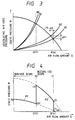
- the air flow amount range during operation is different for suction nozzle having a large opening area such as a general floor use suction nozzle 7 and for a suction nozzle being made narrower at a tip end and having a small opening area such as a crevice use suction nozzle 8 as shown in Fig. 2.
- Fig. 3 is a view of an aerodynamic characteristic in which the general floor use suction nozzle 7 is mounted on the cleaner main body.
- a curve P1 shows an output static pressure curve of the electric driven blower motor.
- Curves A1 and A2 show the air flow pressure drop of the general floor use suction nozzle 7 at the condition when the filter member of the vacuum cleaner is not clogged.
- the curve A1 gives an upper limit value of the air flow amount Q(a) when the filter member is not clogged and the curve A2 gives a lower limit value of the air flow amount Q(a) when the filter member is not clogged.
- ⁇ H1 is a fluctuating width of the static pressure H due to the general floor use suction nozzle 7 and ⁇ Q1 is a fluctuating width of the air flow amount Q(a) due to the general floor use suction nozzle 7.
- the air flow pressure drop at the suction nozzle portion reduces according to the reduction of the air flow amount Q.
- the static pressure fluctuating width ⁇ H1 which is the difference between the curve lines A1 and A2, which is the fluctuating width of the ventilating air loss pressure during the cleaning operation, is made small, and the curves A1 and A2 converge as the air flow amount approaches zero as shown in Fig. 3.
- Curves B1 and B2 show the air flow pressure drop at the condition when the filter member of the vacuum cleaner is clogged and, compared with the curves A1 and A2, the air flow pressure drop is large and increases according to the clog of the filter member.
- the curve B1 gives an upper limit value of the air flow amount Q(b) when the filter member is clogged and the curve B2 gives a lower limit value of the air flow amount Q(b) when the filter member is clogged.
- the difference between the curves B1 and B2 is the fluctuating width due to the above stated cleaning operation and also is the pressure drop fluctuating width at the suction nozzle portion corresponding to the air flow amount Q(b). Further, the air flow amount Q(b) shows the lower limit of the actual use scope of the vacuum cleaner's dust suction performance characteristic.
- the operating range of the vacuum cleaner having the general floor use suction nozzle 7 is between the air flow amount Q(a) and the air flow amount Q(b) as shown in Fig. 4.
- the non-operating range of the vacuum cleaner having the general floor use suction nozzle 7 is below the air flow amount Q(b) as shown in Fig. 4.
- a curve P2 indicates a suction performance characteristic during a strong operation having 100% voltage for the vacuum cleaner and a curve P3 indicates a suction performance characteristic during a weak operation having 50% voltage for the vacuum cleaner, respectively.
- Fig. 5 the aerodynamic characteristic in case that the crevice use suction nozzle 8 is mounted on the cleaner is shown in Fig. 5.
- the output static pressure curve P1 of the electric driven blower motor is same as the curve P1 of Fig. 3; since the opening area of the crevice use suction nozzle 8 is small, the air flow pressure drop is large.
- the curve C1 gives an upper limit value of the air flow amount Q(c) when the filter member is not clogged and the curve C2 gives a lower limit value of the air flow amount Q(c) when the filter member is not clogged.
- ⁇ H2 is a fluctuating width of the static pressure H due to the crevice use suction nozzle 8 and ⁇ Q2 is a fluctuating width of the air flow amount Q(c) due to the crevice use suction nozzle 8.
- a curve D1 is an upper limit value of the air flow amount Q(d) when the filter member is clogged and a curve D2 is a lower limit value of the air flow amount Q(d) when the filter member is clogged.
- the operating range of the vacuum cleaner having the crevice use suction nozzle 8 is between the air flow amount Q(c) and the air flow amount Q(d) as shown in Fig. 6.
- the non-operating range of the vacuum cleaner having the crevice use suction nozzle 8 is below the air flow amount Q(d) as shown in Fig. 6.
- the curve C2 shows the upper limit of the air flow pressure drop fluctuation when the crevice use suction nozzle 8 is moved on the surface to be cleaned. Since the opening area of the crevice use suction nozzle 8 is small, the opening area of the crevice use suction nozzle 8 contacts to adhere closely to the surface to be cleaned and at this time the air flow pressure drop is high.
- the fluctuating widths between the curves C1 and C2 are larger than the fluctuating widths between the curves A1 and A2 of the general floor use suction nozzle 7.
- the air flow amount is at the lower limit Q(d) of the operating range.
- the air flow pressure drop curve is indicated by the curve D1
- the upper limit of the ventilating air loss pressure fluctuation is indicated by the curve D2.
- the air flow amount range Q(a) - Q(b), which is the operating range of a suction nozzle having a large opening area such as the general floor use suction nozzle 7 differs from the air flow amount range Q(c) - Q(d) which is the operating range of a suction nozzle having a small opening area such as the crevice use suction nozzle 8.
- the air flow amount Q(a) is higher than the air flow amount Q(c)
- the air flow amount Q(b) is higher than the air flow amount Q(d).
- the operating range which is the air flow amount range that can actually be used and the non-operating range which is not used because of insufficient dust suction performance are shown in Fig. 4 and Fig. 6 corresponding to Fig. 3 and Fig. 5.
- the suction performance characteristic is set to decrease the suction force in the air flow amount range below air flow amount Q(b), this decrease of the suction force occurs too early for the suction nozzle having the small opening area such as the crevice use suction nozzle 8, accordingly there is a defect in which the suction force may become weak at the actual use scope.
- the suction performance characteristic is set to decrease the suction force in the air flow amount range below air flow amount Q(d)
- the suction nozzle having the large opening area such as the general floor use suction nozzle 7
- the suction nozzle having the large opening area such as the general floor use suction nozzle 7
- the electric driven blower motor in the prior art vacuum cleaner employs a chopper control system inverter driven brushless direct motor.
- a chopper control system inverter driven brushless direct motor for the vacuum cleaner is disclosed in, for example Japanese Patent Laid-Open No. 214219/1985.
- a predetermined suction force is obtained according to the control of the rotational speed of the brushless direct motor.
- An object of the present invention is to provide a vacuum cleaner wherein electric power consumption and noise production are kept low by detecting the operating condition of a suction nozzle of the cleaner from variations of operating parameters and automatically adapting the suction performance to the detected operating condition.
- the kind (type) of suction nozzle fitted to the vacuum cleaner can be detected from the variations of operating parameters.
- a surface to be cleaned can be discriminated automatically.
- a suction performance characteristic can be improved corresponding to the kind of surface to be cleaned.
- a vacuum cleaner comprises a detecting apparatus for detecting changing parameters which fluctuate according to an operation of a suction nozzle, the changing parameters being e.g. a static pressure, an air flow amount and an electric current, and a controlling apparatus for controlling a suction performance of an electric driven blower motor corresponding to a detected value of the detecting apparatus,
- the controlling apparatus When the suction nozzle is operated, the controlling apparatus increases the suction performance, and when the operation of the suction nozzle is stopped, the controlling apparatus decreases the suction performance.
- the first lower limit value of the air flow amount range at the actual use scope is set and the second lower limit value is set to a smaller air flow amount than the first lower limit value. At the air flow amount range lower than the second limit value, the suction performance is decreased widely.
- the suction performance can be controlled to be increased by a predetermined amount, and when no load fluctuation occurs, the suction performance is maintained at low level.
- the changing parameters such as the static pressure, the air flow amount and the electric current, which fluctuate according to the operation of the suction nozzle, are detected and when the fluctuation exceeds a predetermined level during a predetermined period, it is possible to judge that the cleaner is in a cleaning condition.
- the suction performance by the predetermined amount the necessary suction force for cleaning operation can be obtained. Further, when the load fluctuation is not detected within the predetermined period, by decreasing the suction performance by the predetermined amount, the electric power saving and the low noise generation for the vacuum cleaner can be attained.
- the suction performance is lowered and the electric power saving and the low noise generation for the vacuum cleaner can be obtained.
- the suction performance is improved automatically and therefore the suction performance suitable to the cleaning operation can be obtained. It is possible to control automatically the suction performance according to the frequency of the operations of the suction nozzle.
- a vacuum cleaner in which different kinds of suction nozzles are used inter-changeably comprises a control unit which sets beforehand air flow amount ranges for actual use of the different kinds of suction nozzles, and changes over and selects an air flow amount range being suited to a respective suction nozzle in a case of an exchange of the suction nozzle.
- the air flow amount range above the upper limit of the air flow amount under the use of the respective suction nozzle is the non-cleaning condition in which the suction nozzle is lifted from the cleaning portion.
- the electric power saving and the noise reduction for the vacuum cleaner can be attained by lowering the output of the electric driven blower motor.
- the air flow amount range below the lower limit of the air flow amount under the use of the respective suction nozzle is within the domain in which the dust suction ability is insufficient.
- the output of the electric driven blower motor is decreased, so that the operator can notice that the filter member reaches maximum clogging and, at the same time, the electric power saving and the noise reduction for the vacuum cleaner can be attained by lowering the output of the electric driven blower motor.
- the absorption and release can be carried out easily by lowering the output of the electric driven blower motor.
- a vacuum cleaner comprises an electric driven blower motor, a detecting apparatus for detecting a change of an operation condition of the vacuum cleaner, and a controlling apparatus for controlling the electric driven blower motor according to a detected value of the detecting apparatus.
- the vacuum cleaner comprises a means for selecting and changing over automatically different kinds of suction performance characteristics according to a fluctuating width of a changing parameter of the operation condition by having the different kinds of suction performance characteristics of the vacuum cleaner represented by a vacuum degree and an air flow amount and further by detecting a change of the operation condition of the vacuum cleaner in accordance with a load fluctuation due to a reciprocating movement of the suction nozzle of the vacuum cleaner on a cleaning portion to be cleaned.
- the operation suction performance characteristics having been set beforehand, the most suitable operation characteristic for the respective cleaning portion to be cleaned can be determined automatically. Further, in accordance with this detected result, the automatic control operation is carried out.
- the careful control operation can be carried out with the suction characteristic corresponding to the respective nature of the portion to be cleaned. Accordingly, the suction characteristic of the vacuum cleaner can be improved in comparison with the conventional vacuum cleaner in which only one kind of the operation characteristic is corresponded against the different nature of the surface to be cleaned.
- the change of the operation condition of the vacuum cleaner is detected according to the load fluctuation of the suction nozzle of the vacuum cleaner and the respective cleaning portion to be cleaned is discriminated automatically.
- a vacuum cleaner comprises a brushless direct current motor as an electric driven blower motor and a chopper control system inverter apparatus controlling the rotational speed, and the electric driven blower motor is provided in a cleaner main body.
- the brushless direct current motor has an operating range of a chopper control duty of factor 100%.
- the brushless direct current motor is a synchronous motor having permanent magnets for generating a magnet field
- an inverter apparatus controls a rotational speed by changing a duty factor so as to reach a command value of the rotational speed.
- the brushless direct current motor rotates with a value which balances the load torque.
- the specification of the brushless direct current motor is determined so as to set the counter-electromotive voltage generated in an armature winding to be equal to a power source voltage. Therefore, at the load condition more than above stated, only the rotational speed is lowered, but no excessive increase of the input power is caused.
- the electric current increases to an amount fitting to the reduction of the counter-electromotive voltage of the lower rotational speed, and this increase in the input power is restrained saturated within a predetermined amount.
- the over-load operation can be prevented easily, further the high speed rotation due to an abnormal rotational speed command value in the controlling apparatus can be prevented, therefore an improved vacuum cleaner can be obtained.
- over-load prevention control does not depend on control processing programs for preventing an over-load operation, it is very useful at the safety aspect even when at the worst the micro-computer malfunctions.
- the chopper control duty of factor becomes almost 100%. Then the chopper control does not work or may work a little, the higher harmonic component caused by the intermittence is small, therefore the system efficiency including the inverter apparatus and the brushless direct current motor can be realized under the best condition. Namely, the high efficiency for the vacuum cleaner can be obtained at the high load side, for example, the increase in heat generation can be reduced.
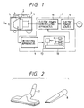
- Fig. 1 is a block diagram showing a structure of a vacuum cleaner 1 and a controlling apparatus 6 thereof.
- the vacuum cleaner 1 comprises an electric driven blower motor 2, a cleaner main body 3, a filter member 4 for filtering dusts and a dust collecting case 5.
- the controlling apparatus 6 is represented outside the cleaner main body 3 using a block diagram.
- the controlling apparatus 6 is realized in the cleaner main body 3 in the form of a circuit or a programmed micro-computer.
- the controlling apparatus 6 is composed of an executing and processing apparatus 10 for executing and processing a detected value of a detecting apparatus 9 and outputting a command value to an electric power controlling apparatus 11, and an electric power source 12 for supplying electric power to each of the above stated apparatuses.
- the executing and processing apparatus 10 includes a suction nozzle etc. discriminating apparatus 13.
- the detecting apparatus 9 detects parameters of the electric driven blower motor 2 through an air flow amount sensor, a pressure sensor, an electric current sensor and a rotational speed sensor. The parameters are changed according to an operating condition of the vacuum cleaner 1.
- the detecting apparatus 9 outputs directly a detected amount indicating an air flow amount, or a combination of the detected amounts, or the air flow amount is detected indirectly by the execution using the executing and processing apparatus 10.
- the discriminating apparatus 13 for the suction nozzle etc. is included in the executing processing apparatus 10.
- the discriminating apparatus 13 discriminates a fluctuating width of the above stated changing parameters or an interval of a fluctuating time etc. and further discriminates the kind of suction nozzle mounted on the cleaner main body 3.
- the fluctuating width is small.
- the fluctuating width is large. Therefore, it is possible to discriminate the kind of suction nozzle using a predetermined judging value.
- a first lower limit value of the operating range of the air flow amount is set at an air flow amount Q(b) and a second lower limit value is set at an air flow amount Q(d), respectively.
- the cleaner is controlled according to the low suction performance characteristic indicated by the curve P2, above the air flow amount Q(b), it operates at a high suction performance characteristic indicated by the curve P3.
- the overall characteristic is given by a route (0) ⁇ (1) ⁇ (2) ⁇ (3) ⁇ (4) ⁇ (5).
- the vacuum cleaner 1 when the vacuum cleaner 1 is operated at the air flow amount range between the air flow amount Q(b) and the air flow amount Q(d), the number of fluctuations having a width exceeding the predetermined judging value detected by the detecting apparatus 9 is counted, and it is determined whether the number of fluctuations in every predetermined period is within a predetermined range. It can be discriminated that the crevice use suction nozzle 8 having the small opening area is mounted on the cleaner main body 3 and further it can be discriminated that the crevice use suction nozzle 8 is operated under the actual use scope condition.
- the vacuum cleaner 1 is commanded and controlled so as to increase the predetermined suction performance by the executing and processing apparatus 10.
- the vacuum cleaner 1 can operate at the suction performance characteristic indicated by the curve P4 (the route (6)-(7)-(8)) which is indicated by the two-dots chain curve and is suitable for the crevice use suction nozzle a having the small opening area.
- FIG. 9 Another embodiment of the increase and decrease control for the suction performance will be explained in Fig. 9 - Fig. 12B.
- Fig. 10A shows an example in which the operation time is shown in the horizontal axis and then the detected value of the load fluctuation is detected according to the change of the static pressure.
- curves P I and P II are output suction performance characteristics and curves E1 and E2 are air flow pressure drop characteristics, respectively.
- the above stated control is performed as the basic control for the vacuum cleaner 1.
- the change-over of the rotational speed N of the electric driver blower motor 2 indicated in the portions (A) and (B) in Fig. 10B is repeated frequently at every detected predetermined period T due to the existence of fluctuations, the suction performance is changed repeatedly and rapidly. Since this causes an inconvenience by generating fluctuations such as beat sounds and vibrations of the vacuum cleaner 1, the reaction of the suction performance may be slowed down by performing a change-over when no load fluctuation is detected during up to n predetermined periods T (n x T).
- curves Pa, Pb, Pc and Pd are output suction performance characteristics and a curve F is a ventilating air loss pressure characteristic.
- the vacuum cleaner 1 is operated to increase or to decrease the suction performance by amounts which are proportional to the number of fluctuations of the static pressure H due to the operation of the suction nozzle during the predetermined detecting period T.
- the static pressure value Ha of the initial low level suction performance is set as a setting value in the case in which the static pressure H does not fluctuate for a long time.
- the minimum static pressure value Hb of the suction performance is set as a setting value in the case in which the operation number of the suction nozzle is small, i.e. when the number of fluctuations is small, such as one time and two times per predetermined detecting period T.
- the vacuum cleaner 1 is operated at the rotational speeds Nc and Nd so as to increase the suction performance of the static pressure Hc and of the static pressure Hd by predetermined amounts.
- the maximum static pressure value Hd of the suction performance is set as a setting value in the case in which the operation number is large, namely the suction nozzle is operated at a high frequency.
- the vacuum cleaner 1 is controlled to lower the suction performance corresponding to the frequency.
- the suction performance of the vacuum cleaner 1 is controlled to be high under the condition of a quick speed operation and is controlled to be low under the condition of a slow speed operation. Thereby it is possible to realize the automatic control of the suction performance most suitable to the operator.
- the suction force Hb is secured for the case that the suction nozzle is operated at least more than once.
- control range of air flow amount is indicated in the example having the control range between the air flow amount Q(b) and the air flow amount Q(d) shown in Fig. 8.
- control range of the air flow amount Q is not limited to the above stated example.
- the fluctuating width is small.
- the fluctuating width is large because of the repeated adhesion and release of the suction nozzle from the surface. Therefore, it is possible to discriminate the kind of the suction nozzle according to a predetermined judging value.
- the upper limit value of the air flow amount Q for the control change-over or the lower limit value of the air flow amount for the control change-over, or both values of the air flow amount for the control change-over are renewed to a predetermined setting value which has been set beforehand.
- curves P11, P12 and P13 are output suction performance characteristics.
- curves P14, P15 and P16 are output suction performance characteristics.
- Fig. 13 shows a case that the fluctuating width of the detected value is small and it is judged at the side of the route A of Fig. 15.
- This case is suited to the suction nozzle having the large opening area such as the general floor use suction nozzle 7, and the control upper limit value of the air flow amount Q(a1) and the control lower limit value of the air flow amount Q(b1) have been set.
- control limit values are set respectively corresponding to the maximum air flow amount in which the filter member 4 is not clogged when the suction nozzle is contacted to the floor portion within the operating range of the general floor use suction nozzle 7 and to the lower limit value of the air flow amount when the filter member 4 is clogged.
- the curves P11, P12, P13 in Fig. 13 are output characteristics of the electric driven blower motor 2.
- the output characteristic curves P11, P12 and P13 have been set beforehand so as to be suited to the above stated general floor use suction nozzle 7 having the large opening area. By changing over between these characteristics, a predetermined suction performance characteristic can be attained.
- the range of a route (0) ⁇ (1) above the upper limit value of the air flow amount Q(a1) in Fig. 13 is the non-cleaning condition in which the suction nozzle is lifted into the air etc..
- the route (0) ⁇ (1) in Fig. 13 by lowering the output, the electric power saving and the noise reduction for the vacuum cleaner can be attained.
- the route of (6) ⁇ (7) below the lower limit of the air flow amount Q(b1) is a domain where the dust suction ability is insufficient.
- the operator can notice the condition in which the filter member 4 reaches the clogging limitation, and at the same time the electric power saving and the noise reduction effects for the vacuum cleaner can be attained.
- the range of the air flow amount Q(a1) - Q(b1) is the operating range used for cleaning. Within this operating range, the most suitable suction performance characteristic can be realized which is suited to the general floor use suction nozzle 7.
- the embodiment shown in Fig. 13 can be realized by control by commands from the executing and processing apparatus 10. Namely, it is possible to change over between the output characteristic curve P13 indicated by the route (2)-(3) and the output characteristic curve P12 indicated by the route (4)-(5) via route (3) ⁇ (4).
- Fig. 14 shows a case that the fluctuating width of the detected value is large and it is judged at the side of the route B of Fig. 15.
- This case is suited to the suction nozzle having the small opening area such as the crevice use suction nozzle 8, and the control upper limit value of the air flow amount Q(c1) and the control lower limit value of the air flow amount Q(d1) have been set.
- the curves P14, P15, P16 in Fig. 14 are the output characteristic curves of the electric driven blower motor 2.
- the output characteristic curves P14, P15 and P16 have been set beforehand so as to be suited to the above stated crevice use suction nozzle 8. Similar to the example shown in Fig. 13, by changing over between the curves the suction performance characteristic passing through the route (0)' ⁇ (1)' ⁇ (2)' ⁇ (3)' ⁇ (4)' ⁇ (5)' ⁇ (6)' ⁇ (7)' can be realized.
- the curve P14 representing an output characteristic of the electric driven blower motor 2 is equal to the curve P11 shown in Fig. 13 and also the curve P15 representing an output characteristic of the electric driven blower motor 2 is equal to the curve P12 shown in Fig. 13, respectively.
- the curves P14 and P15 shown in Fig. 14 and the curves P11 and P12 shown in Fig. 13 be equal, respectively.
- the kind of the suction nozzle is judged according to the width of the fluctuation of the detected value, and in accordance with the judging result, it is possible to operate with the most suitable suction performance characteristic within the air flow amount range which is suited to the suction nozzle mounted on the cleaner.
- the fluctuating width may be compared with a plurality of discriminating values and the kind of the suction nozzle thus be discriminated, therefore the operation characteristic control can be carried out which best suits the respective suction nozzle.
- Fig. 16 is a vacuum degree - air flow amount characteristic diagram showing one example of an operation suction performance characteristic in a vacuum cleaner according to the present invention.
- an operation characteristic A2 is used for the floor as a surface to be cleaned.
- This operation characteristic is a combination of a constant air flow amount Q24 and a constant vacuum degree H22, and at an air flow amount below a limit Q21 the operation is under a constant vacuum degree H21.
- an operation characteristic B2 is used for tatami as a surface to be cleaned
- an operation characteristic C2 is used for carpet as a surface to be cleaned, respectively.
- a sloping characteristic between the air flow amount Q21 and Q22 shows under the constant rotational speed operation of the electric driven blower motor.
- the air flow amount is less than Q21, the operation is under the constant vacuum degree H21. Namely, below Q21, the air flow amount is in a domain in which the air flow amount is lowered by the clogging of the filter member in the vacuum cleaner. This domain is not the operating range during the vacuum cleaner use, so that there is only one operation characteristic.
- the suction nozzle when the suction nozzle is moved reciprocatively on the surface, the adhesion degree between the suction nozzle and the surface changes, further the vacuum degree of the interior portion of the vacuum cleaner, the electric current of the electric driven blower motor and the suction air flow amount of the electric driven blower motor change.
- the above stated changing amounts are detected as the changing amounts of the operation condition in the vacuum cleaner.
- the above stated changing amounts of the vacuum cleaner that is, the changing amounts of the vacuum degree, the electric current and the air flow amount due to the reciprocating motion of the suction nozzle of the vacuum cleaner differ according to the surface to be cleaned when the same suction nozzle is used. Therefore, the kind of surface can be judged, and then the operation characteristic property is changed over corresponding to the judged result.
- Fig. 17 is a view in which the load fluctuating curve during the reciprocating motion of the suction nozzle on the surface is superposed against the vacuum degree - air flow amount characteristic diagram shown in Fig. 16.
- curves a2, b2, c2 and d2 are load characteristics of the suction nozzle.
- the load curve of the suction nozzle changes between the curve a2 and the curve b2.
- the motion point on the operation characteristic A2 lies between a point (e) and a point (f) under the constant air flow amount Q24.
- the vacuum degree changes between a value of H(e) and a value of H(f) according to the reciprocating motion of the suction nozzle of the vacuum cleaner 1.
- the changing width of the vacuum degree is a width indicated by V.
- the changing width of the vacuum degree on characteristic A2 is a width indicated by W.
- the changing width of the vacuum degree on the operation characteristic A2 is a width indicated by X.
- the portion to be cleaned is discriminated according to the difference in the changing width of the vacuum degree.
- the changing width of the vacuum degree is a width indicated by Z in the case of the constant air flow amount Q22 and the changing width of the vacuum degree is a width indicated by Y in the case of the constant air flow amount Q23.
- the above stated discriminating threshold value may be normalized by dividing the changing width of the vacuum degree by the mean value and making the changing rate of the vacuum degree a dimensionless number
- the change of the vacuum degree is used as an example for the changing amount of the operation condition of the vacuum cleaner 1 under the operation of the constant air flow amount Q.
- the change of the electric current value of the electric driven blower motor 2 in accordance with the load fluctuation of the suction nozzle of the vacuum cleaner can be used as the changing amount of the operation condition of the vacuum cleaner 1.
- the change of the air flow amount Q and the change of the electric current can be used as the changing amount of the operation condition of the vacuum cleaner 1.
- the change of the vacuum degree, the change of the air flow amount Q and the change of the electric current can be used as the changing amount of the operation condition of the vacuum cleaner.
- Fig. 18 is a control block diagram showing one embodiment of the vacuum cleaner according to the present invention.
- a brushless direct current motor 25 is used as the electric driven blower motor, and the rotating number is varied according to an inverter control.
- Fig. 18 commercial electric power (alternating current 100V) supplied from a socket (not shown) is rectified to direct current in a converter portion 21 and supplied to an inverter portion 23 through an electric current detecting portion 22.
- the inverter portion 23 generates three-phase alternative current by a firing signal from a main controlling circuit 24 and supplies it to the brushless direct current motor 25.
- the brushless direct current motor 25 comprises a rotor position detecting sensor 26 and a position of a rotor is fed back to the main controlling circuit 24. Further, a pressure sensor 27 for detecting the vacuum degree of the interior portion of the vacuum cleaner is connected to the main controlling circuit 24.
- the air flow amount sensor when the vacuum cleaner is operated at a constant air flow amount, the air flow amount sensor is used and further utilizing the output power negative feedback control may be performed with respect to the rotating number of the brushless direct current motor 25.
- the rotating number of the brushless direct current motor 25 is calculated according to the electric current value from the electric current detecting portion 22 and the rotor position detecting sensor 26.
- the air flow amount is determined from these values and the operation under the constant air flow amount is carried out according to this determined air flow amount.
- operation under constant vacuum degree and operation under constant rotational speed is controlled by the pressure sensor 27 and the rotor position detecting sensor 26, respectively.
- the vacuum degree, the air flow amount and the electric current value of the brushless direct current motor 25 are always monitored as the changing condition of the operation condition of the vacuum cleaner 1 and then the change-over of the operation suction performance characteristic of the vacuum cleaner is carried out.
- Fig. 19 is a whole construction explanation view showing a speed controlling apparatus comprising a brushless direct current motor 36 and an inverter controlling apparatus 31.
- Fig. 20 and Fig. 21 are suction performance characteristics of the vacuum cleaner employing the chopper control system inverter driven brushless direct current motor 36 as a driving source
- Fig. 22 is a suction performance characteristic of the vacuum cleaner comprising an input power limiting function according to the present invention.
- the inverter controlling apparatus 31 obtains the direct current voltage E d from an alternative current power source 32 through a rectifier circuit 33 and a smoothing circuit 34 and supplies it to an inverter apparatus 35.
- the inverter apparatus 35 is a 120° resistance type inverter comprising transistors TR1 - TR6 and reflux diodes D1 - D6.
- An alternative current output voltage of the inverter apparatus 35 is controlled according to a chopper-operation for the conductive voltage side (electric angle 120°) of the positive electric voltage side transistors TR1 - TR3 of the direct current voltage E d by receiving a pulse width modulation.
- a low resistor R1 is connected between common emitter terminals of the transistors TR4 - TR6 and common anode terminals of the reflux diodes D4 - D6.
- the brushless direct current motor 36 comprises a rotor 36a having tow poles type permanent magnets generating the magnetic field, and a stator into which an armature winding 36b inserted. A winding current flowing in the armature winding 36b flows also to the low resistor R1, and a load current I D of the brushless direct current motor 36 is detected according to the voltage drop of the low resistor R1.
- a controlling circuit for controlling the speed of the brushless direct current motor 36 comprises a micro-computer 37 including CPU, ROM and RAM, a magnetic pole position detecting circuit 39 for detecting a magnetic pole position of the rotor 36a by receiving an output power from a Hall element 38, an electric current detecting circuit 40 for detecting a value of the load electric current I D according to the voltage drop of the low resistor R1, a base driver 41 for driving the transistors TR1 - TR6, and a speed command circuit 42 for transmitting a standard speed to the micro-computer 37.
- the electric current detecting circuit 40 detects the load electric current I D by receiving the voltage drop of the low resistor R1 and forms an electric current detecting signal 40S by an A/D converter (not shown).
- the various kinds of processing programs necessary for driving the brushless direct current motor 36 for example programs such as a speed executing processing, a command taking-in processing and a speed controlling processing are memorized.
- the above stated RAM in the micro-computer 37 comprises a memorizing portion for taking-in the various data which are necessary for carrying out of the above stated various kinds of processing programs.
- the transistors TR1 - TR6 receive a firing signal 37S from the micro-computer 37 and are driven by the base driver 41.
- a voltage commanding circuit 43 forms a latter stated chopper signal. Namely, in the brushless direct current motor 36, the winding current flowing to the armature winding 36b corresponds to an output torque of this brushless direct current motor 36 and controls the winding current at every rotation position, therefore it is possible to carry out a continuous control for the output torque.
- Fig. 20 shows a suction performance characteristic of the vacuum cleaner 1 employing the brushless direct current motor 36 as a driving source.
- the air flow amount Q passing through the vacuum cleaner is indicated, and in the vertical axis, the static pressure H presenting the suction force of the vacuum cleaner, a rotational speed N of the brushless direct current motor 36 and an input power W i are indicated.
- the motion range of the vacuum cleaner has the range from the point Q31 of the maximum motion to the point Q32 of the minimum motion.
- a vicinity of the maximum motion point Q31 corresponds to the state in which the suction nozzle port is removed from the surface to be cleaned, and in this state electric power consumption is highest.
- the input power W i exceeds the tolerance input power upper limit value W1 and causes the over load condition.
- this embodiment of the present invention in the range between the air flow amount Q33 corresponding to the non-cleaning condition in which the suction nozzle is lifted up and the air flow amount Q31, no more suction force than necessary is produced. Therefore this embodiment of the present invention is constituted so that at the vicinity of the above stated range, the input power W i is restrained automatically.
- a counter-electromotive force corresponding to the rotation of the rotor 36a is generated in the above stated armature winding 36b portion.
- the magnetomotive force of the rotor 36a and the winding number of the armature winding 36b are set so as to balance the power source voltage against the counter-electromotive force and further they are set so that the air flow amount Q of the load condition which has a duty of factor 100% becomes the air flow amount Q34.
- the rotating number N4 is lowered gradually from the rotational speed command value according to the increase in the load, and the input power W i increases gradually and becomes saturated. Therefore, it is possible to control the increase in the input power W i automatically with the predetermined value which is lower than the tolerance input power upper limit value W1.
Landscapes
- Engineering & Computer Science (AREA)
- Mechanical Engineering (AREA)
- Electric Vacuum Cleaner (AREA)
Claims (19)
- Staubsauger mit einer Erfassungseinrichtung (9) zum Erfassen veränderlicher Parameter, die entsprechend der Betätigung einer Saugdüse (7, 8) schwanken, einer Regeleinheit (10) zum Regeln der Saugleistung eines elektrischen Gebläses entsprechend einer von der Erfassungseinrichtung (9) erfaßten Größe, wobei die Regeleinheit (10) eingerichtet ist, um die Saugleistung zu erhöhen, wenn die Erfassungseinrichtung (9) Schwankungen der veränderlichen Parameter erfaßt,
dadurch gekennzeichnet, daß
die veränderlichen Parameter wenigstens einen statischen Druck, eine Luftströmungsrate und einen elektrischen Strom umfassen, und daß die Regeleinheit (10) die Saugleistung auf eine vorgegebene Saugleistung verringert, wenn länger als über einen vorgegebenen Zeitraum keine Schwankungen erfaßt werden. - Staubsauger nach Anspruch 1, dadurch gekennzeichnet, daß die Regeleinheit (10) eingerichtet ist, um die Saugleistung kumulativ um einen jeweils vorgegebenen Betrag zu erhöhen, wenn die Saugdüse (7, 8) auf der zu reinigenden Oberfläche innerhalb jedes vorgegebenen Zeitraums bewegt wird, und die Saugleistung kumulativ um jeweils einen vorgegebenen Betrag zu verringern, wenn die Saugdüse (7, 8) nicht auf der zu reinigenden Oberfläche bewegt wird.
- Staubsauger nach einem der Ansprüche 1 bis 2, dadurch gekennzeichnet, daß die Regeleinheit (10) einen oberen Grenzwert und einen unteren Grenzwert der Luftströmungsrate setzt, die einen nutzbaren Bereich der Luftströmungsrate definieren, und daß sie die Saugleistung verringert, wenn die Luftströmungsrate oberhalb oder unterhalb dieses nutzbaren Bereichs liegt.
- Staubsauger nach Anspruch 3, dadurch gekennzeichnet, daß die Regeleinheit (10) einen zweiten unteren Grenzwert der Luftströmungsrate setzt, und daß die Saugleistung entsprechend der Schwankung der veränderlichen Parameter geregelt wird, wenn die Luftströmungsrate in einem Bereich zwischen den beiden unteren Grenzwerten liegt, und auf hohem Niveau gehalten wird, wenn die Luftströmungsrate in einem Bereich zwischen dem zweiten unteren Grenzwert und dem oberen Grenzwert liegt.
- Staubsauger nach Anspruch 2, dadurch gekennzeichnet, daß der vorgegebene Erhöhungsbetrag zur Anzahl der Schwankungen der veränderlichen Parameter (7, 8) proportional ist.
- Staubsauger nach Anspruch 1 oder 2, dadurch gekennzeichnet, daß die Regeleinheit (10) die Saugleistung auf einen der Anzahl von Schwankungen der veränderlichen Parameter proportionalen Wert oder eine vorgegebene Saugleistungskennlinienfunktion erhöht.
- Staubsauger nach einem der vorhergehenden Ansprüche, dadurch gekennzeichnet, daß eine Mehrzahl von Saugdüsen (7, 8) austauschbar verwendet werden können, wobei die Regeleinheit (10) vorab Luftströmungsratenbereiche für die Verwendung der Saugdüsen (7, 8) setzt und beim Austausch der Saugdüse umschaltet und einen für die jeweilige Saugdüse (7 oder 8) geeigneten Luftströmungsratenbereich wählt.
- Staubsauger nach Anspruch 7, dadurch gekennzeichnet, daß die Regeleinheit (10) eine Mehrzahl von oberen Grenzwerten der Luftströmungsrate setzt, die den Öffnungsflächen der Mehrzahl von Saugdüsen (7, 8) entsprechen, und die Saugleistung verringert, wenn der jeweilige obere Grenzwert für die Saugdüse (7, 8) überschritten wird.
- Staubsauger nach Anspruch 8, dadurch gekennzeichnet, daß eine Unterscheidungseinrichtung (13) die Art von Saugdüse (7, 8) anhand der Erfassung einer Schwankungsbreite und eines Schwankungszustands der veränderlichen Parameter erfaßt, die aufgrund der Bewegung der Saugdüse auf der zu reinigenden Oberfläche schwanken, und daß eine Umschalteinrichtung einen oberen Grenzwert für die geregelte Luftströmungsrate entsprechend einem Signal von der Unterscheidungseinrichtung (13) umschaltet.
- Staubsauger nach Anspruch 9, dadurch gekennzeichnet, daß die Regeleinheit (10) in einem Bereich unterhalb der oberen Grenze der geregelten Luftströmungsrate eine vorgegebene Saugleistungskennlinie einregelt.
- Staubsauger nach einem der vorhergehenden Ansprüche, dadurch gekennzeichnet, daß eine Mehrzahl von Saugdüsen (7, 8) austauschbar verwendet werden können, die Luftströmungsratenerfassungseinrichtung (9) vorgesehen ist, um während des Reinigungsbetriebs die Saugluftströmungsrate zu erfassen, die Saugleistung des elektrischen Gebläsemotors (2) entsprechend der erfaßten Luftströmungsrate geregelt wird und die Regeleinheit (10) eine Mehrzahl von oberen Grenzwerten der Luftströmungsraten und eine Mehrzahl von unteren Grenzwerten der Luftströmungsraten entsprechend den Öffnungsflächen der Mehrzahl von Saugdüsen (7, 8) setzt, und daß die Saugleistung verringert wird, wenn die Luftströmungsrate oberhalb des jeweiligen oberen Grenzwerts oder unterhalb des jeweiligen unteren Grenzwerts der Saugdüse liegt.
- Staubsauger nach einem der vorhergehenden Ansprüche, dadurch gekennzeichnet, daß die Regeleinheit (10) die Saugleistung auf Grundlage einer erfaßten Änderung des Betriebszustands des Staubsaugers entsprechend Lastschwankungen während der Hin- und Herbewegung der Saugdüse (7, 8) auf einer zu reinigenden Oberfläche regelt.
- Staubsauger nach einem der vorhergehenden Ansprüche, dadurch gekennzeichnet, daß die Regeleinheit (10) entsprechend der Schwankungsbreite des veränderlichen Parameters automatisch zwischen einer Mehrzahl von Saugleistungskennlinien, einer Betriebskennlinie bei konstanter Luftströmungsrate, einer Betriebskennlinie bei konstantem Unterdruck, und einer Betriebskennlinie bei konstanter Drehgeschwindigkeit des elektrischen Gebläsemotors (2) umschaltet.
- Staubsauger nach Anspruch 12 oder 13, dadurch gekennzeichnet, daß die Regeleinheit (10) zwischen den mehreren Saugleistungskennlinien umschaltet durch Erfassen der Änderung des Betriebszustandes des Staubsaugers anhand von Lastschwankungen während der Betätigung der Saugdüse (7, 8), indem als Schwankungsbreite das Maß der Änderung des Unterdrucks im Staubsauger und eine Stromstärke des elektrischen Gebläsemotors (2) verwendet werden, die durch die Lastschwankungen zum Schwanken gebracht werden, und indem diese Schwankungsbreite mit einem Beurteilungsschwellwert verglichen wird, der vorab für jede Saugleistungskennlinie vorgegeben wurde.
- Staubsauger nach einem der vorhergehenden Ansprüche, dadurch gekennzeichnet, daß der Gebläsemotor (2) ein bürstenloser Gleichstrommotor mit einem nutzbaren Bereich des Tastverhältnisses der Zerhackerregelung von 100% ist.
- Verfahren zum Regeln eines Staubsaugers mit den Schrittena) Erfassen veränderlicher Parameter, darunter wenigstens statischer Druck, Luftströmungsrate und Stromstärke, die entsprechend der Betätigung einer Saugdüse (7, 8) schwanken,b) Regeln der Saugleistung eines elektrischen Gebläses entsprechend einer in Schritt a) erfaßten Größe,c) Erfassen aus Schwankungen der veränderlichen Parameter, ob die Saugdüse (7, 8) auf der zu reinigenden Oberfläche bewegt wird undd) Erhöhen der Saugleistung, wenn die Saugdüse (7, 8) auf der zu reinigenden Oberfläche bewegt wird und Verringern der Saugleistung auf ein vorgegebenes Niveau, wenn die Saugdüse (7, 8) auf der zu reinigenden Oberfläche für einen längeren als einen vorgegebenen Zeitraum nicht bewegt wird.
- Verfahren nach Anspruch 16, dadurch gekennzeichnet, daß wenn die Saugdüse (7, 8) auf der zu reinigenden Oberfläche in jedem vorgegebenen Zeitraum bewegt wird, die Saugleistung kumulativ um einen jeweils vorgegebenen Betrag erhöht wird, und daß wenn die Saugdüse (7, 8) auf der zu reinigenden Oberfläche nicht bewegt wird, die Saugleistung kumulativ um einen jeweils vorgegebenen Betrag verringert wird.
- Verfahren nach einem der Ansprüche 16 bis 17, dadurch gekennzeichnet, daß ein oberer Grenzwert und ein unterer Grenzwert für die Saugleistung gesetzt werden, die einen nutzbaren Bereich der Luftströmungsrate definieren, und daß die Saugleistung verringert wird, wenn die Luftströmungsrate oberhalb oder unterhalb dieses nutzbaren Bereichs liegt.
- Verfahren nach Anspruch 18, dadurch gekennzeichnet, daß ein zweiter unterer Grenzwert der Luftströmungsrate gesetzt wird, daß die Saugleistung entsprechend der Bewegung der Saugdüse auf der zu reinigenden Oberfläche geregelt wird, wenn die Luftströmungsrate in dem Bereich zwischen den zwei unteren Grenzwerten liegt, und daß die Saugleistung auf hohem Niveau gehalten wird, wenn die Luftströmungsrate in dem Bereich zwischen dem zweiten unteren Grenzwert und dem oberen Grenzwert liegt.
Applications Claiming Priority (8)
| Application Number | Priority Date | Filing Date | Title |
|---|---|---|---|
| JP26894889A JP2839583B2 (ja) | 1989-10-18 | 1989-10-18 | 電気掃除機 |
| JP268948/89 | 1989-10-18 | ||
| JP24688/90 | 1990-02-03 | ||
| JP2024688A JPH03228725A (ja) | 1990-02-03 | 1990-02-03 | 電気掃除機 |
| JP2024689A JP3039558B2 (ja) | 1990-02-03 | 1990-02-03 | 電気掃除機 |
| JP24689/90 | 1990-02-03 | ||
| JP2066632A JP2992303B2 (ja) | 1990-03-16 | 1990-03-16 | 電気掃除機 |
| JP66632/90 | 1990-03-16 |
Publications (2)
| Publication Number | Publication Date |
|---|---|
| EP0423670A1 EP0423670A1 (de) | 1991-04-24 |
| EP0423670B1 true EP0423670B1 (de) | 1994-12-28 |
Family
ID=27458182
Family Applications (1)
| Application Number | Title | Priority Date | Filing Date |
|---|---|---|---|
| EP90119688A Expired - Lifetime EP0423670B1 (de) | 1989-10-18 | 1990-10-15 | Staubsauger und Verfahren zum Regeln desselben |
Country Status (4)
| Country | Link |
|---|---|
| US (1) | US5381584A (de) |
| EP (1) | EP0423670B1 (de) |
| KR (1) | KR930011916B1 (de) |
| DE (1) | DE69015557D1 (de) |
Families Citing this family (23)
| Publication number | Priority date | Publication date | Assignee | Title |
|---|---|---|---|---|
| US5255409A (en) * | 1990-07-18 | 1993-10-26 | Sanyo Electric Co., Ltd. | Electric vacuum cleaner having an electric blower driven in accordance with the conditions of floor surfaces |
| FR2708188A1 (fr) * | 1993-07-28 | 1995-02-03 | Philips Laboratoire Electroniq | Aspirateur avec des moyens de détection des sols et de réglage de la puissance du moteur en fonction du sol détecté. |
| DE4327070C1 (de) * | 1993-08-12 | 1995-04-06 | Gerhard Kurz | Vorrichtung zur Regelung der Leistungsaufnahme eines Staubsaugers |
| US5987696A (en) * | 1996-12-24 | 1999-11-23 | Wang; Kevin W. | Carpet cleaning machine |
| WO1999009874A1 (en) * | 1997-08-25 | 1999-03-04 | Koninklijke Philips Electronics N.V. | Electrical surface treatment device with an acoustic surface type detector |
| DE19813434A1 (de) * | 1998-03-27 | 1999-09-30 | Proair Geraetebau Gmbh | Naßsauger |
| US6595753B1 (en) * | 1999-05-21 | 2003-07-22 | A. Vortex Holding Company | Vortex attractor |
| JP3656901B2 (ja) * | 2000-08-29 | 2005-06-08 | 東芝テック株式会社 | 電気掃除機用電動送風機のインバータ制御回路を用いた駆動制御回路及びこの駆動制御回路を用いた電気掃除機 |
| JP2005013460A (ja) * | 2003-06-26 | 2005-01-20 | Matsushita Electric Ind Co Ltd | 充電式電気掃除機 |
| US7251858B2 (en) * | 2004-01-23 | 2007-08-07 | Panasonic Corporation Of North America | Floor care apparatus with multiple agitator speeds and constant suction power |
| US7161316B2 (en) * | 2004-11-02 | 2007-01-09 | General Electric Company | Method and apparatus for discrete speed compensated torque step motor control |
| US20080034532A1 (en) * | 2007-02-07 | 2008-02-14 | Tai-Her Yang | Off-load reduced input power energy saving low noise air vacuum cleaner |
| DE102007041067A1 (de) * | 2007-08-30 | 2009-03-05 | BSH Bosch und Siemens Hausgeräte GmbH | Verfahrbare Vorrichtung zum Durchführen von Arbeiten an vorzugsweise ebenen Flächen |
| DE102011006541A1 (de) * | 2011-03-31 | 2012-10-04 | BSH Bosch und Siemens Hausgeräte GmbH | Staubsauger und Verfahren zum saugdruckabhängigen Betreiben eines Staubsaugers |
| ITUD20130149A1 (it) * | 2013-11-13 | 2015-05-14 | Longhi Appliances S R L Con Un Ico Socio De | Aspirapolvere |
| KR20160037460A (ko) * | 2014-09-29 | 2016-04-06 | 엘지전자 주식회사 | 진공 청소기 |
| KR101645808B1 (ko) | 2014-10-01 | 2016-08-04 | 엘지전자 주식회사 | 진공 청소기 |
| US10375901B2 (en) | 2014-12-09 | 2019-08-13 | Mtd Products Inc | Blower/vacuum |
| DE102017115331A1 (de) * | 2017-07-10 | 2019-01-10 | Miele & Cie. Kg | Verfahren zum Betrieb eines Elektromotors eines Gebläses, vorzugsweise eines Staubsaugers |
| DE102017120800A1 (de) * | 2017-09-08 | 2019-03-14 | Vorwerk & Co. Interholding Gmbh | Saugreinigungsgerät mit einer Saugdüse |
| WO2019143700A1 (en) | 2018-01-17 | 2019-07-25 | Tti (Macao Commercial Offshore) Limited | System and method for operating a cleaning system based on a surface to be cleaned |
| KR102306753B1 (ko) * | 2019-07-19 | 2021-09-30 | 엘지전자 주식회사 | 청소기의 제어 방법 |
| SE544198C2 (en) * | 2019-11-14 | 2022-03-01 | Husqvarna Ab | Improved dust extractor motor control |
Family Cites Families (10)
| Publication number | Priority date | Publication date | Assignee | Title |
|---|---|---|---|---|
| DE1920640A1 (de) * | 1969-04-23 | 1970-11-05 | Philips Patentverwaltung | Staubsauger mit einem elektromotorisch angetriebenen Geblaese |
| DE2032476A1 (de) * | 1970-07-01 | 1972-01-05 | Licentia Gmbh | Staubsauger, dessen Kompressordrehzahl sich selbsttätig an die verschiedenen Arbeitsprozesse anpaßt |
| SE412840B (sv) * | 1978-03-20 | 1980-03-24 | Electrolux Ab | Dammsugare med regleranordning for undertryck och luftflode |
| JPS61280831A (ja) * | 1985-05-31 | 1986-12-11 | 三洋電機株式会社 | 真空掃除機 |
| KR940002923B1 (ko) * | 1986-10-08 | 1994-04-07 | 가부시키가이샤 히타치세이사쿠쇼 | 전기청소기의 운전방법 및 그 장치 |
| JP2606842B2 (ja) * | 1987-05-30 | 1997-05-07 | 株式会社東芝 | 電気掃除機 |
| EP0320878B1 (de) * | 1987-12-15 | 1995-03-22 | Hitachi, Ltd. | Verfahren für den Betrieb eines Staubsaugers |
| JPH01223923A (ja) * | 1988-03-04 | 1989-09-07 | Hitachi Ltd | 電気掃除機 |
| KR910006885B1 (ko) * | 1988-08-15 | 1991-09-10 | 미쯔비시 덴끼 가부시기가이샤 | 전기소제기의 파워브러시 |
| DE8901003U1 (de) * | 1989-01-21 | 1989-04-06 | Interlava Ag, Lugano, Ch |
-
1990
- 1990-10-15 EP EP90119688A patent/EP0423670B1/de not_active Expired - Lifetime
- 1990-10-15 DE DE69015557T patent/DE69015557D1/de not_active Expired - Lifetime
- 1990-10-16 KR KR1019900016409A patent/KR930011916B1/ko not_active IP Right Cessation
-
1993
- 1993-11-04 US US08/145,729 patent/US5381584A/en not_active Expired - Fee Related
Also Published As
| Publication number | Publication date |
|---|---|
| DE69015557D1 (de) | 1995-02-09 |
| KR930011916B1 (ko) | 1993-12-22 |
| EP0423670A1 (de) | 1991-04-24 |
| US5381584A (en) | 1995-01-17 |
| KR910007481A (ko) | 1991-05-30 |
Similar Documents
| Publication | Publication Date | Title |
|---|---|---|
| EP0423670B1 (de) | Staubsauger und Verfahren zum Regeln desselben | |
| US4958406A (en) | Method and apparatus for operating vacuum cleaner | |
| US5243732A (en) | Vacuum cleaner with fuzzy logic control | |
| US5075607A (en) | Method and apparatus for operating vacuum cleaner | |
| US7698777B2 (en) | Vacuum cleaner | |
| EP0413359A1 (de) | Staubsauger und Verfahren zum Bestimmen der Natur des zu reinigenden Bodens | |
| EP0397205A1 (de) | Staubsauger | |
| EP0681808A2 (de) | Elektronisches Steuersystem für einen Staubsauger | |
| EP0458057B1 (de) | Verfahren zum Betreiben eines Staubsaugers | |
| EP3473153B1 (de) | Staubsauger und verfahren zur steuerung eines motors einer bürste des staubsaugers | |
| KR101284492B1 (ko) | 전기 진공 청소기 | |
| JP2679988B2 (ja) | 電気掃除機 | |
| JP3326126B2 (ja) | 電気掃除機 | |
| JPH10146303A (ja) | 電気掃除機 | |
| JPH0687675B2 (ja) | 電気掃除機 | |
| JP2992303B2 (ja) | 電気掃除機 | |
| JP2001008871A (ja) | 電気掃除機 | |
| JP2904653B2 (ja) | 電気掃除機 | |
| JPH01227729A (ja) | 電気掃除機の制御方法 | |
| JPH1147053A (ja) | 電気掃除機の入力制御装置 | |
| JPH0614856A (ja) | 電気掃除機 | |
| RU1771684C (ru) | Система управлени пылесосом | |
| JPS63249487A (ja) | 電気掃除機 | |
| JPH0661420B2 (ja) | 空気清浄機の制御回路 | |
| JPH10192209A (ja) | 電気掃除機 |
Legal Events
| Date | Code | Title | Description |
|---|---|---|---|
| PUAI | Public reference made under article 153(3) epc to a published international application that has entered the european phase |
Free format text: ORIGINAL CODE: 0009012 |
|
| 17P | Request for examination filed |
Effective date: 19901218 |
|
| AK | Designated contracting states |
Kind code of ref document: A1 Designated state(s): DE GB |
|
| 17Q | First examination report despatched |
Effective date: 19920722 |
|
| GRAA | (expected) grant |
Free format text: ORIGINAL CODE: 0009210 |
|
| AK | Designated contracting states |
Kind code of ref document: B1 Designated state(s): DE GB |
|
| PG25 | Lapsed in a contracting state [announced via postgrant information from national office to epo] |
Ref country code: DE Effective date: 19941228 |
|
| REF | Corresponds to: |
Ref document number: 69015557 Country of ref document: DE Date of ref document: 19950209 |
|
| PLBE | No opposition filed within time limit |
Free format text: ORIGINAL CODE: 0009261 |
|
| STAA | Information on the status of an ep patent application or granted ep patent |
Free format text: STATUS: NO OPPOSITION FILED WITHIN TIME LIMIT |
|
| 26N | No opposition filed | ||
| REG | Reference to a national code |
Ref country code: GB Ref legal event code: IF02 |
|
| PGFP | Annual fee paid to national office [announced via postgrant information from national office to epo] |
Ref country code: GB Payment date: 20080922 Year of fee payment: 19 |
|
| PG25 | Lapsed in a contracting state [announced via postgrant information from national office to epo] |
Ref country code: GB Free format text: LAPSE BECAUSE OF NON-PAYMENT OF DUE FEES Effective date: 20091015 |