EP0423568B1 - A disengageable four-wheel-drive transmission system for motor vehicles - Google Patents
A disengageable four-wheel-drive transmission system for motor vehicles Download PDFInfo
- Publication number
- EP0423568B1 EP0423568B1 EP90119174A EP90119174A EP0423568B1 EP 0423568 B1 EP0423568 B1 EP 0423568B1 EP 90119174 A EP90119174 A EP 90119174A EP 90119174 A EP90119174 A EP 90119174A EP 0423568 B1 EP0423568 B1 EP 0423568B1
- Authority
- EP
- European Patent Office
- Prior art keywords
- transmission system
- gearbox
- drive
- hydraulic clutch
- differential
- Prior art date
- Legal status (The legal status is an assumption and is not a legal conclusion. Google has not performed a legal analysis and makes no representation as to the accuracy of the status listed.)
- Expired - Lifetime
Links
Images


Classifications
-
- B—PERFORMING OPERATIONS; TRANSPORTING
- B60—VEHICLES IN GENERAL
- B60K—ARRANGEMENT OR MOUNTING OF PROPULSION UNITS OR OF TRANSMISSIONS IN VEHICLES; ARRANGEMENT OR MOUNTING OF PLURAL DIVERSE PRIME-MOVERS IN VEHICLES; AUXILIARY DRIVES FOR VEHICLES; INSTRUMENTATION OR DASHBOARDS FOR VEHICLES; ARRANGEMENTS IN CONNECTION WITH COOLING, AIR INTAKE, GAS EXHAUST OR FUEL SUPPLY OF PROPULSION UNITS IN VEHICLES
- B60K23/00—Arrangement or mounting of control devices for vehicle transmissions, or parts thereof, not otherwise provided for
- B60K23/08—Arrangement or mounting of control devices for vehicle transmissions, or parts thereof, not otherwise provided for for changing number of driven wheels, for switching from driving one axle to driving two or more axles
- B60K23/0808—Arrangement or mounting of control devices for vehicle transmissions, or parts thereof, not otherwise provided for for changing number of driven wheels, for switching from driving one axle to driving two or more axles for varying torque distribution between driven axles, e.g. by transfer clutch
-
- B—PERFORMING OPERATIONS; TRANSPORTING
- B60—VEHICLES IN GENERAL
- B60K—ARRANGEMENT OR MOUNTING OF PROPULSION UNITS OR OF TRANSMISSIONS IN VEHICLES; ARRANGEMENT OR MOUNTING OF PLURAL DIVERSE PRIME-MOVERS IN VEHICLES; AUXILIARY DRIVES FOR VEHICLES; INSTRUMENTATION OR DASHBOARDS FOR VEHICLES; ARRANGEMENTS IN CONNECTION WITH COOLING, AIR INTAKE, GAS EXHAUST OR FUEL SUPPLY OF PROPULSION UNITS IN VEHICLES
- B60K17/00—Arrangement or mounting of transmissions in vehicles
- B60K17/34—Arrangement or mounting of transmissions in vehicles for driving both front and rear wheels, e.g. four wheel drive vehicles
- B60K17/348—Arrangement or mounting of transmissions in vehicles for driving both front and rear wheels, e.g. four wheel drive vehicles having differential means for driving one set of wheels, e.g. the front, at one speed and the other set, e.g. the rear, at a different speed
- B60K17/35—Arrangement or mounting of transmissions in vehicles for driving both front and rear wheels, e.g. four wheel drive vehicles having differential means for driving one set of wheels, e.g. the front, at one speed and the other set, e.g. the rear, at a different speed including arrangements for suppressing or influencing the power transfer, e.g. viscous clutches
-
- F—MECHANICAL ENGINEERING; LIGHTING; HEATING; WEAPONS; BLASTING
- F16—ENGINEERING ELEMENTS AND UNITS; GENERAL MEASURES FOR PRODUCING AND MAINTAINING EFFECTIVE FUNCTIONING OF MACHINES OR INSTALLATIONS; THERMAL INSULATION IN GENERAL
- F16C—SHAFTS; FLEXIBLE SHAFTS; ELEMENTS OR CRANKSHAFT MECHANISMS; ROTARY BODIES OTHER THAN GEARING ELEMENTS; BEARINGS
- F16C19/00—Bearings with rolling contact, for exclusively rotary movement
- F16C19/02—Bearings with rolling contact, for exclusively rotary movement with bearing balls essentially of the same size in one or more circular rows
- F16C19/04—Bearings with rolling contact, for exclusively rotary movement with bearing balls essentially of the same size in one or more circular rows for radial load mainly
- F16C19/06—Bearings with rolling contact, for exclusively rotary movement with bearing balls essentially of the same size in one or more circular rows for radial load mainly with a single row or balls
-
- F—MECHANICAL ENGINEERING; LIGHTING; HEATING; WEAPONS; BLASTING
- F16—ENGINEERING ELEMENTS AND UNITS; GENERAL MEASURES FOR PRODUCING AND MAINTAINING EFFECTIVE FUNCTIONING OF MACHINES OR INSTALLATIONS; THERMAL INSULATION IN GENERAL
- F16C—SHAFTS; FLEXIBLE SHAFTS; ELEMENTS OR CRANKSHAFT MECHANISMS; ROTARY BODIES OTHER THAN GEARING ELEMENTS; BEARINGS
- F16C33/00—Parts of bearings; Special methods for making bearings or parts thereof
- F16C33/30—Parts of ball or roller bearings
- F16C33/58—Raceways; Race rings
- F16C33/581—Raceways; Race rings integral with other parts, e.g. with housings or machine elements such as shafts or gear wheels
Definitions
- the subject of the present invention is a disengageable four-wheel-drive transmission system for a motor vehicle with a transverse gearbox, including a toothed input member meshed with a toothed output member of the gearbox, a front differential which drives the drive shafts of the front wheels of the vehicle, a rear differential which drives the drive shafts of the rear wheels of the vehicle, and means for distributing the torque between the front and rear differentials as specified in the preamble of claim 1.
- the means for distributing the torque are usually constituted by an epicyclic differential, possibly in association with a FERGUSON-type sliding viscous coupling, a TORSEN-GLEASON distributor, or the like.
- These known transmission systems do not enable the four-wheel drive to be disengaged selectively when it is not necessary or desired, so as to limit the transmission of torque to the front wheels of the vehicle only or to the rear wheels only.
- the torque is distributed between the front and rear differentials in proportions which are fixed or which can be varied only in proportion to any variations in the road-holding of the front and rear wheels.
- the object of the present invention is to provide a four-wheel-drive transmission system of the type defined above which can be engaged or disengaged selectively in order to limit the drive either to the front wheels of the vehicle or to the rear wheels and which, in the four-wheel-drive condition, can distribute the transmitted torque to the front and rear wheels in dependence on the prevailing operating parameters of the transmission system and, in particular, on the torque transmitted by the engine of the vehicle.
- the electronic control unit is arranged to pilot the operation of the hydraulic clutch in dependence on the instantaneous torque transmitted by the engine of the vehicle.
- this is achieved by virtue of the fact that the toothed input member of the transmission system and the toothed output member of the gearbox each have helical teeth, and the fact that the input member of the transmission system is supported for rotation by the gearbox housing by means of an axial rolling bearing with a portion which is resiliently deformable in dependence on the axial load transmitted by the helical teeth and which has an associated deformation transducer operatively connected to the electronic control unit and adapted to supply thereto electrical signals indicative of the deformation of the deformable portion of the bearing.
- the electronic unit pilots the gradual engagement and disengagement of the hydraulic clutch in dependence on the electrical signals supplied by the deformation transducer.
- the axial bearing conveniently has an outer race which is mounted with clearance relative to the gearbox housing and has an outer annular projection clamped axially relative to the housing and constituting the resiliently deformable portion with which one or more extensometers are associated.
- an internal combustion engine is intended for mounting in the front part of a motor vehicle with its axis arranged transverse the length of the vehicle, indicated A in Figures 2 and 3.
- the engine 1 has a gearbox 2 with a main shaft and a countershaft (not shown) which are also arranged transverse the length A of the vehicle.
- a housing is indicated 3 and houses a generally conventional differential 4, shown in Figures 2 and 3, whose box 5 has two opposed tubular appendages 6, 7 from which the drive shafts 8, 9 of the front wheels of the vehicle project.
- a helical gear is carried by the countershaft of the gearbox 2 and meshes with an external helical ring gear 11 carried by a wheel 12 having a tubular hub 13 which is supported for rotation by the housing 3, coaxially with the drive shaft 8, by means of a radial rolling bearing 14 and an axial rolling bearing 15 which will be referred to again below.
- the wheel 12 is coupled for rotation with a sprocket 16 used for driving a revolution-counter and has an internal ring gear 17 meshed with a hollow toothed member 18 which is permanently coupled at 19 for rotation with the tubular appendage 6 of the box 5 of the front differential 4.
- the other tubular appendage 7 of the box 5 of the front differential 4 is permanently coupled at 20 for rotation with a tubular element 21 which extends coaxially with the other front drive shaft 9 and constitutes a first entrainment member of a hydraulic clutch, generally indicated 22, which is also housed in the housing 3.
- the hydraulic clutch 22 also includes a drum 23 which constitutes a second entrainment member and is supported for rotation by the first entrainment member 21.
- the drum 23 is coupled permanently at 24 for rotation with a hollow member, generally indicated 25, which contains the front differential 4 and is supported for free rotation by the housing 3, coaxially with the tubular appendages 6 and 7.
- a bevel gear 26 is fixed to the hollow member 4 and is meshed with a bevel pinion 27 at the inner end of a shaft 28 supported for rotation within a hollow appendage 29 of the housing 3, arranged along the length A of the vehicle.
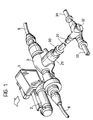
- the opposite end of the shaft 28 from the bevel pinion 27 is connected by means of a constant velocity universal joint, generally indicated 30 in Figure 1, to a propeller shaft 31 for transmitting the torque to a rear differential 32.
- the differential 32 transmits the torque to the drive shafts 33, 34 of the rear wheels of the vehicle.
- the hydraulic clutch 22 includes two sets of friction discs 35, 36 coupled alternately for rotation with the first entrainment member 21 and the second entrainment member 23 and axially slidable relative thereto.
- a thrust disc 37 is associated with the discs 35, 36 and can be moved axially by a piston 38 which is sealingly slidable in a cylinder 39 defining a thrust chamber 40 connected by means of a distributor, schematically indicated 41, to a supply 42 of pressurised hydraulic fluid.
- the distributor 41 is controlled automatically by means of an electronic control unit 43, in the manner explained below, so as to keep the chamber 40 of the hydraulic clutch 22 discharged or to connect the thrust chamber 40 gradually to the supply 42.
- the hydraulic clutch 22 is disengaged so that the friction discs 35 and 36, and hence the first entrainment member 21 and the second entrainment member 23, are freely rotatable relative to each other. Consequently, in this condition, the rotation of the output gear 10 of the gearbox is transmitted solely to the front differential 4 and not to the bevel gears 26-27, or hence to the rear differential 32, so that the transmission system only drives the front wheels.
- the rotation of the first entrainment member 21 of the hydraulic clutch 22 is also transmitted to the second entrainment member 23, and hence to the rear differential 32 by means of the hollow member 25, the bevel gears 26, 27 and the shafts 28 and 31, in proportion to the coupling force between the friction discs 35, 36.
- the transmission system thus achieves four-wheel drive with a distribution between the front and rear wheels which is variable up to a maximum of 50% when the hydraulic clutch 22 is in the fully-engaged condition and the coefficient of friction and the weight of the axles are uniform.
- the engagement and disengagement of the hydraulic clutch 22 is achieved gradually by the electronic control unit 43 in dependence on operating parameters of the transmission system and of the vehicle in which it is fitted, by means of suitable inputs 45 supplied with signals generated by corresponding sensors and indicative of these parameters.
- These parameters which may comprise, for example, the speed at which the vehicle is moving, the difference in the rates of rotation of the front and rear axles, the rate of rotation of the engine, environmental data, and travelling conditions (dry, wet or snowy ground) also include, according to the invention, the torque delivered, at the time by the engine, in the driving condition or in the coasting condition.
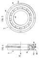
- the invention provides the device shown in greater detail in Figures 3 to 6.
- This consists of a particular conformation of the axial rolling bearing 15 which, as stated, together with the radial rolling bearing 14, rotatably supports the tubular hub 13 of the wheel 12 carrying the external helical ring gear 11 which is meshed with the helical output gear 10 of the gearbox 2.
- This bearing 15 includes an inner race 46 which is clamped axially between a ring nut 47 screwed onto the tubular hub 13 and a spacer 58 interposed between the bearing 15 and the bearing 14 and an outer race 48 which is mounted with clearance relative to the housing 3 of the gearbox 2.
- the outer race 48 has an external annular projection 49 which is clamped axially between a stop 50 of the housing 3 and a spacer 51 and is connected to the outer race 48 by means of a resiliently deformable portion 152.
- Deformation transducers constituted, for example, by extensometers 53 are mounted on the resiliently deformable portion 152 and are connected electrically to the electronic control unit 43.
- the annular projection 49 has rounded sides 54 which are in contact with the corresponding surfaces of the appendage 50 and the spacer 51 and may have gaps locally.
- annular projections 49 may be two annular projections 49 rather than one, as in the embodiment of Figures 3 to 6, and they may have an asymmetrical configuration, as indicated 55 in the variant of Figure 7.
Landscapes
- Engineering & Computer Science (AREA)
- Chemical & Material Sciences (AREA)
- Combustion & Propulsion (AREA)
- Transportation (AREA)
- Mechanical Engineering (AREA)
- Arrangement And Driving Of Transmission Devices (AREA)
Applications Claiming Priority (2)
| Application Number | Priority Date | Filing Date | Title |
|---|---|---|---|
| IT06786889A IT1238112B (it) | 1989-10-10 | 1989-10-10 | Trasmissione a trazione integrale disinseribile per autoveicoli |
| IT6786889 | 1989-10-10 |
Publications (3)
| Publication Number | Publication Date |
|---|---|
| EP0423568A2 EP0423568A2 (en) | 1991-04-24 |
| EP0423568A3 EP0423568A3 (en) | 1991-09-04 |
| EP0423568B1 true EP0423568B1 (en) | 1994-03-02 |
Family
ID=11305937
Family Applications (1)
| Application Number | Title | Priority Date | Filing Date |
|---|---|---|---|
| EP90119174A Expired - Lifetime EP0423568B1 (en) | 1989-10-10 | 1990-10-05 | A disengageable four-wheel-drive transmission system for motor vehicles |
Country Status (5)
| Country | Link |
|---|---|
| US (1) | US5098352A (it) |
| EP (1) | EP0423568B1 (it) |
| DE (1) | DE69007005T2 (it) |
| ES (1) | ES2049883T3 (it) |
| IT (1) | IT1238112B (it) |
Families Citing this family (13)
| Publication number | Priority date | Publication date | Assignee | Title |
|---|---|---|---|---|
| US5407024A (en) * | 1992-06-24 | 1995-04-18 | Borg-Warner Automotive, Inc. | On demand vehicle drive system |
| US6000488A (en) * | 1992-06-24 | 1999-12-14 | Borg-Warner Automotive, Inc. | Motor vehicle transfer case |
| US5370018A (en) * | 1993-03-03 | 1994-12-06 | Eaton Corporation | Internally vented interaxle differential assembly lockout shift unit |
| US7048935B2 (en) * | 1995-04-27 | 2006-05-23 | The United States Of America As Represented By The Department Of Health And Human Services | Cyanovirin conjugates and matrix-anchored cyanovirin and related compositions and methods of use |
| US6158303A (en) * | 1997-03-21 | 2000-12-12 | Mazda Motor Corporation | Transfer case for four wheel drive vehicle |
| US5845546A (en) * | 1997-04-04 | 1998-12-08 | Borg-Warner Automotive, Inc. | Multiple chamber twin clutch axle |
| US6231470B1 (en) | 1998-10-23 | 2001-05-15 | Borgwarner Inc. | Transfer case for use with transaxle |
| US7857723B2 (en) * | 2005-06-02 | 2010-12-28 | Dana Automotive Systems Group, Llc | Transaxle unit with integrated power take-off unit and torque coupling device |
| US8776935B1 (en) * | 2008-11-25 | 2014-07-15 | George H. Morgan | Bi-directional overrunning clutch assembly |
| DE102010039447A1 (de) * | 2010-08-18 | 2012-02-23 | Zf Friedrichshafen Ag | Verteilergetriebeeinrichtung eines Fahrzeugantriebsstranges |
| US8795126B2 (en) | 2012-05-14 | 2014-08-05 | American Axle & Manufacturing, Inc. | Disconnectable driveline for all-wheel drive vehicle |
| US11933370B2 (en) | 2021-06-08 | 2024-03-19 | Dana Belgium N.V. | Vehicle transmission with disconnect devices |
| US11718170B2 (en) | 2021-11-30 | 2023-08-08 | Dana Belgium N.V. | Vehicle transmission with disconnect device for power take in |
Citations (2)
| Publication number | Priority date | Publication date | Assignee | Title |
|---|---|---|---|---|
| EP0076148A1 (en) * | 1981-09-29 | 1983-04-06 | Fuji Jukogyo Kabushiki Kaisha | System for controlling the transmission torque of a four-wheel drive vehicle |
| EP0311141A2 (en) * | 1987-10-09 | 1989-04-12 | Nissan Motor Co., Ltd. | Active driving force control for four-wheel drive vehicle |
Family Cites Families (16)
| Publication number | Priority date | Publication date | Assignee | Title |
|---|---|---|---|---|
| US3845671A (en) * | 1973-02-12 | 1974-11-05 | Chrysler Corp | Full time slip controlled four wheel drive |
| GB2107002A (en) * | 1981-10-02 | 1983-04-20 | Rolls Royce | Journal bearing |
| US4715467A (en) * | 1984-03-27 | 1987-12-29 | Fuji Jukogyo Kabushiki Kaisha | Control system for a four-wheel drive vehicle |
| JPS61146637A (ja) * | 1984-12-19 | 1986-07-04 | Aisin Warner Ltd | 4輪駆動車 |
| US4718301A (en) * | 1985-04-02 | 1988-01-12 | Steyr-Daimler-Puch Aktiengesellschaft | Driving mechanism for motor vehicles having at least two live axles |
| US4705134A (en) * | 1985-04-30 | 1987-11-10 | Fuji Jukogyo Kabushiki Kaisha | System for controlling a transfer clutch of a four-wheel drive vehicle |
| DE3668586D1 (de) * | 1985-08-30 | 1990-03-08 | Mazda Motor | Drehmomentsteuersystem fuer fahrzeuge. |
| DE3611093A1 (de) * | 1986-04-03 | 1987-10-08 | Opel Adam Ag | Kraftfahrzeug mit allradantrieb |
| JPS62247924A (ja) * | 1986-04-21 | 1987-10-29 | Toyota Central Res & Dev Lab Inc | 4輪駆動車 |
| EP0248577B1 (en) * | 1986-05-23 | 1990-04-11 | Toyota Jidosha Kabushiki Kaisha | Power transfer device for four-wheel drive |
| JPS62275841A (ja) * | 1986-05-23 | 1987-11-30 | Toyota Motor Corp | 車両用動力分配装置 |
| JPS62289430A (ja) * | 1986-06-06 | 1987-12-16 | Toyoda Mach Works Ltd | 4輪駆動装置 |
| JPS63190937A (ja) * | 1987-01-30 | 1988-08-08 | Isuzu Motors Ltd | 多板クラツチ装置 |
| JP2548229B2 (ja) * | 1987-10-09 | 1996-10-30 | 日産自動車株式会社 | 四輪駆動車の駆動力配分制御装置 |
| FR2631703B1 (fr) * | 1988-05-17 | 1990-08-10 | Look Sa | Roue motrice de cycle ou similaire, comportant un systeme de detection du couple transmis, et cycle equipe d'une telle roue |
| DE68926685T2 (de) * | 1988-07-28 | 1996-10-10 | Fuji Heavy Ind Ltd | Kraftübertragung für ein zwei- und vierradangetriebenes Fahrzeug |
-
1989
- 1989-10-10 IT IT06786889A patent/IT1238112B/it active IP Right Grant
-
1990
- 1990-10-05 DE DE69007005T patent/DE69007005T2/de not_active Expired - Fee Related
- 1990-10-05 EP EP90119174A patent/EP0423568B1/en not_active Expired - Lifetime
- 1990-10-05 US US07/593,429 patent/US5098352A/en not_active Expired - Fee Related
- 1990-10-05 ES ES90119174T patent/ES2049883T3/es not_active Expired - Lifetime
Patent Citations (2)
| Publication number | Priority date | Publication date | Assignee | Title |
|---|---|---|---|---|
| EP0076148A1 (en) * | 1981-09-29 | 1983-04-06 | Fuji Jukogyo Kabushiki Kaisha | System for controlling the transmission torque of a four-wheel drive vehicle |
| EP0311141A2 (en) * | 1987-10-09 | 1989-04-12 | Nissan Motor Co., Ltd. | Active driving force control for four-wheel drive vehicle |
Also Published As
| Publication number | Publication date |
|---|---|
| IT8967868A0 (it) | 1989-10-10 |
| ES2049883T3 (es) | 1994-05-01 |
| DE69007005D1 (de) | 1994-04-07 |
| EP0423568A2 (en) | 1991-04-24 |
| US5098352A (en) | 1992-03-24 |
| EP0423568A3 (en) | 1991-09-04 |
| IT1238112B (it) | 1993-07-07 |
| DE69007005T2 (de) | 1994-06-09 |
Similar Documents
| Publication | Publication Date | Title |
|---|---|---|
| EP0423568B1 (en) | A disengageable four-wheel-drive transmission system for motor vehicles | |
| US4650028A (en) | Viscous coupling apparatus for on-demand four wheel drive system | |
| EP0413436B1 (en) | Torque distribution control system for a four-wheel drive motor vehicle | |
| JPH0542653Y2 (it) | ||
| EP0396323B1 (en) | Torque distribution control system for a four-wheel drive motor vehicle | |
| US5527225A (en) | Full time four-wheel drive system | |
| US6540640B2 (en) | Power on demand differential | |
| US5161636A (en) | All-wheel drive tractor | |
| US5711389A (en) | Tandem rear drive axle assembly | |
| JP2003106340A (ja) | ツイン式電子トルク制御装置を備える一体式車軸モジュール | |
| EP0409529B1 (en) | Torque distribution control system for a four-wheel drive motor vehicle | |
| US4907672A (en) | Transmission for a four-wheel drive motor vehicle | |
| EP0662402A1 (en) | An electronically controlled differential with a system for controlling torque distribution | |
| US4875978A (en) | Vehicle four wheel drive system | |
| US7083541B2 (en) | Axle drive block with a differential lock | |
| US4672861A (en) | Drive system for automobiles having two driven axles | |
| US5967930A (en) | Adapter for transfer cases | |
| JPS6349526A (ja) | 車両の動力伝達機構 | |
| US3792628A (en) | Torque proportioning and spin limiting differential | |
| US4635504A (en) | Transmission systems for motor vehicles with four-wheel drive | |
| US4643284A (en) | Non-differential drive axle | |
| US5101678A (en) | Coupling device for power transfer | |
| US3473414A (en) | Limited slip geared differential with non-circular gears | |
| JP3319925B2 (ja) | 四輪駆動車両の動力伝達装置 | |
| JP2711404B2 (ja) | 差動歯車装置 |
Legal Events
| Date | Code | Title | Description |
|---|---|---|---|
| PUAI | Public reference made under article 153(3) epc to a published international application that has entered the european phase |
Free format text: ORIGINAL CODE: 0009012 |
|
| AK | Designated contracting states |
Kind code of ref document: A2 Designated state(s): DE ES FR GB SE |
|
| PUAL | Search report despatched |
Free format text: ORIGINAL CODE: 0009013 |
|
| AK | Designated contracting states |
Kind code of ref document: A3 Designated state(s): DE ES FR GB SE |
|
| 17P | Request for examination filed |
Effective date: 19911011 |
|
| 17Q | First examination report despatched |
Effective date: 19921015 |
|
| GRAA | (expected) grant |
Free format text: ORIGINAL CODE: 0009210 |
|
| AK | Designated contracting states |
Kind code of ref document: B1 Designated state(s): DE ES FR GB SE |
|
| REF | Corresponds to: |
Ref document number: 69007005 Country of ref document: DE Date of ref document: 19940407 |
|
| REG | Reference to a national code |
Ref country code: ES Ref legal event code: FG2A Ref document number: 2049883 Country of ref document: ES Kind code of ref document: T3 |
|
| ET | Fr: translation filed | ||
| PG25 | Lapsed in a contracting state [announced via postgrant information from national office to epo] |
Ref country code: GB Effective date: 19941005 |
|
| PG25 | Lapsed in a contracting state [announced via postgrant information from national office to epo] |
Ref country code: SE Effective date: 19941006 Ref country code: ES Free format text: LAPSE BECAUSE OF NON-PAYMENT OF DUE FEES Effective date: 19941006 |
|
| PLBE | No opposition filed within time limit |
Free format text: ORIGINAL CODE: 0009261 |
|
| STAA | Information on the status of an ep patent application or granted ep patent |
Free format text: STATUS: NO OPPOSITION FILED WITHIN TIME LIMIT |
|
| EAL | Se: european patent in force in sweden |
Ref document number: 90119174.2 |
|
| 26N | No opposition filed | ||
| GBPC | Gb: european patent ceased through non-payment of renewal fee |
Effective date: 19941005 |
|
| EUG | Se: european patent has lapsed |
Ref document number: 90119174.2 |
|
| PGFP | Annual fee paid to national office [announced via postgrant information from national office to epo] |
Ref country code: DE Payment date: 19980925 Year of fee payment: 9 |
|
| PGFP | Annual fee paid to national office [announced via postgrant information from national office to epo] |
Ref country code: FR Payment date: 19981030 Year of fee payment: 9 |
|
| PG25 | Lapsed in a contracting state [announced via postgrant information from national office to epo] |
Ref country code: FR Free format text: LAPSE BECAUSE OF NON-PAYMENT OF DUE FEES Effective date: 20000630 |
|
| PG25 | Lapsed in a contracting state [announced via postgrant information from national office to epo] |
Ref country code: DE Free format text: LAPSE BECAUSE OF NON-PAYMENT OF DUE FEES Effective date: 20000801 |
|
| REG | Reference to a national code |
Ref country code: FR Ref legal event code: ST |
|
| REG | Reference to a national code |
Ref country code: ES Ref legal event code: FD2A Effective date: 19951113 |