EP0248577B1 - Power transfer device for four-wheel drive - Google Patents
Power transfer device for four-wheel drive Download PDFInfo
- Publication number
- EP0248577B1 EP0248577B1 EP87304605A EP87304605A EP0248577B1 EP 0248577 B1 EP0248577 B1 EP 0248577B1 EP 87304605 A EP87304605 A EP 87304605A EP 87304605 A EP87304605 A EP 87304605A EP 0248577 B1 EP0248577 B1 EP 0248577B1
- Authority
- EP
- European Patent Office
- Prior art keywords
- differential
- hollow shaft
- transfer device
- mounting case
- gear
- Prior art date
- Legal status (The legal status is an assumption and is not a legal conclusion. Google has not performed a legal analysis and makes no representation as to the accuracy of the status listed.)
- Expired
Links
- 230000005540 biological transmission Effects 0.000 claims description 19
- 230000000694 effects Effects 0.000 claims description 6
- 239000012530 fluid Substances 0.000 claims description 4
- 230000008878 coupling Effects 0.000 description 14
- 238000010168 coupling process Methods 0.000 description 14
- 238000005859 coupling reaction Methods 0.000 description 14
- 230000000717 retained effect Effects 0.000 description 6
- 230000013011 mating Effects 0.000 description 4
- 229920002545 silicone oil Polymers 0.000 description 3
- 230000001143 conditioned effect Effects 0.000 description 2
- 230000007423 decrease Effects 0.000 description 2
- 239000000446 fuel Substances 0.000 description 2
- 238000005259 measurement Methods 0.000 description 2
- 238000002485 combustion reaction Methods 0.000 description 1
Images


Classifications
-
- F—MECHANICAL ENGINEERING; LIGHTING; HEATING; WEAPONS; BLASTING
- F16—ENGINEERING ELEMENTS AND UNITS; GENERAL MEASURES FOR PRODUCING AND MAINTAINING EFFECTIVE FUNCTIONING OF MACHINES OR INSTALLATIONS; THERMAL INSULATION IN GENERAL
- F16D—COUPLINGS FOR TRANSMITTING ROTATION; CLUTCHES; BRAKES
- F16D35/00—Fluid clutches in which the clutching is predominantly obtained by fluid adhesion
- F16D35/005—Fluid clutches in which the clutching is predominantly obtained by fluid adhesion with multiple lamellae
-
- B—PERFORMING OPERATIONS; TRANSPORTING
- B60—VEHICLES IN GENERAL
- B60K—ARRANGEMENT OR MOUNTING OF PROPULSION UNITS OR OF TRANSMISSIONS IN VEHICLES; ARRANGEMENT OR MOUNTING OF PLURAL DIVERSE PRIME-MOVERS IN VEHICLES; AUXILIARY DRIVES FOR VEHICLES; INSTRUMENTATION OR DASHBOARDS FOR VEHICLES; ARRANGEMENTS IN CONNECTION WITH COOLING, AIR INTAKE, GAS EXHAUST OR FUEL SUPPLY OF PROPULSION UNITS IN VEHICLES
- B60K17/00—Arrangement or mounting of transmissions in vehicles
- B60K17/34—Arrangement or mounting of transmissions in vehicles for driving both front and rear wheels, e.g. four wheel drive vehicles
- B60K17/344—Arrangement or mounting of transmissions in vehicles for driving both front and rear wheels, e.g. four wheel drive vehicles having a transfer gear
- B60K17/346—Arrangement or mounting of transmissions in vehicles for driving both front and rear wheels, e.g. four wheel drive vehicles having a transfer gear the transfer gear being a differential gear
- B60K17/3462—Arrangement or mounting of transmissions in vehicles for driving both front and rear wheels, e.g. four wheel drive vehicles having a transfer gear the transfer gear being a differential gear with means for changing distribution of torque between front and rear wheels
- B60K17/3465—Arrangement or mounting of transmissions in vehicles for driving both front and rear wheels, e.g. four wheel drive vehicles having a transfer gear the transfer gear being a differential gear with means for changing distribution of torque between front and rear wheels self-actuated means, e.g. differential locked automatically by difference of speed
Definitions
- the present invention relates to a power transfer device in combination with a power transmission for automotive vehicles, and more particularly to a power transfer device of the type which includes a limited-slip differential arranged to effect limited-slip torque proportional to the difference in rotational speed between the front and rear wheel axles of the vehicle.
- a power transfer device which includes a center differential of the bevel gear type arranged to split the driving torque from a power transmission into two torque delivery paths respectively for front-wheel drive and rear-wheel drive, a front-drive differential of the bevel gear type arranged coaxially with the center differential at one side thereof to transfer the split driving torque from a first side gear of the center differential to front-wheel axles, and an output ring gear for rear-wheel drive arranged coaxially with the center differential at the other side thereof to transfer the split driving torque from a second side gear of the center differential to rear-wheel axles.
- a limited-slip differential in the form of a viscous coupling is assembled within a mounting case for the output ring gear to effect limited-slip torque proportional to the difference in rotational speed between the side gears.
- the limited-slip torque causes an increase of the driving torque at a low speed side and a decrease of the driving torque at a high speed side.
- the limited-slip differential is, however, conditioned to be always driven in operation of the power transfer device. This means that when the power transfer device is operated in a condition where the vehicle is placed on a chassis dynamometer at its front or rear road wheels for measurement of emission gas, rate of fuel consumption, driving torque or the like and for check of meter indication, the limited-slip differential is driven for a long period of time under a large difference in rotational speed between the side gears of the center differential caused by rotation of the front or rear road wheels. This causes frictional heat in the limited-slip differential and results in rise of fluid temperature in the limited-slip differential.
- the power transfer device When the vehicle is trailed in a condition where it is suspended from a tractor at its front or rear road wheels, the power transfer device is operated by rotation of the rear or front road wheels during travel of the tractor. In such a situation, the limited-slip differential is driven for a long period of time under a large difference in rotational speed between the side gears of the center differential. This causes the same problem described above. Furthermore, when the vehicle is trailed in a condition where the front or rear wheel axles are suspended from a tractor, the power transfer device acts to rotate the front or rear road wheels during travel of the tractor.
- the object is attained by providing a power transfer device for four-wheel drive in combination with a power transmission, wherein the limited-slip differential includes first and second rotary elements coupled with each other for relative rotation, the first rotary element being assembled within the mounting case for relative rotation therewith and having a hollow shaft portion aligned with a first hollow shaft which is drivingly connected to the second side gear of the center differential, and the second rotary element being mounted on a second hollow shaft which is drivingly connected at an inner end thereof to the first side gear of the center differential and extends into the interior of the mounting case through the first hollow shaft, and wherein a clutch sleeve is arranged between the center differential and the output ring gear and axially slidably mounted on the first hollow shaft for rotation therewith and being shiftable between a first position where it is engaged with the mounting case and the hollow shaft portion of the first rotary element and a second position where it is disengaged from the mounting case and the hollow shaft portion of the first rotary element and engaged with a casing of the
- the clutch sleeve is further shiftable to a third position where it is engaged with the mounting case and disengaged from the hollow shaft portion of the first rotary element.
- the first rotary element of the limited-slip differential is a drum-like outer casing assembled within the mounting case for relative rotation and having the hollow shaft portion connectable to the first hollow shaft
- the second rotary element of the limited-slip differential is an inner sleeve coupled with the outer casing for relative rotation and mounted on the second hollow shaft for rotation therewith.
- an amount of viscous fluid such as silicone oil is stored and a number of friction discs on the outer casing are interleaved with friction discs on the inner sleeve.
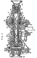
- Fig. 1 illustrates a power transfer device in accordance with the present invention which is adapted to a power transmission 12 for an automotive vehicle of the front-engine front-wheel drive type.
- the power transmission 12 is fixedly mounted to one side of an intemal combustion engine (not shown) through a clutch mechanism 11 in a usual manner.
- the engine is mounted on the vehicle in such a manner that a crankshaft of the engine is transversely placed.
- the power transmission 12 includes a transmission casing 12c secured at one side thereof to a cylinder block of the engine, an input shaft 12a rotatably mounted within the transmission casing 12c and arranged coaxially with the crankshaft of the engine, an output shaft 12b rotatably mounted within the transmission casing 12c and arranged in parallel with the input shaft 12a, a change-speed gearing mounted on the input and output shafts 12a and 12b, and a final drive gearing including an output gear 12d mounted on the output shaft 12b for rotation therewith and arranged in mesh with an input ring gear 14 of the power transfer device.
- the power transfer device is contained within the transmission casing 12c and an additional housing 13 secured thereto, which device comprises a center differential 20a of the bevel gear type arranged to split the driving torque from the power transmission 12 into two torque delivery paths respectively for front-wheel drive and rear-wheel drive, a front-drive differential 20b of the bevel gear type arranged coaxially with the center differential 20a, an output gearing assembly 30a for rear-wheel drive, and a limited-slip differential 30b in the form of a viscous coupling associated with the output gearing assembly 30a.
- a center differential 20a of the bevel gear type arranged to split the driving torque from the power transmission 12 into two torque delivery paths respectively for front-wheel drive and rear-wheel drive
- a front-drive differential 20b of the bevel gear type arranged coaxially with the center differential 20a
- an output gearing assembly 30a for rear-wheel drive
- a limited-slip differential 30b in the form of a viscous coupling associated with the output gearing assembly 30a.
- the center differential 20a includes an input member in the form of a differential casing 21 located within the transmission casing 12c and rotatably supported by a pair of axially spaced bearings carried on the transmission casing 12c, a pair of pinion gears 22a, 22b rotatably carried on the differential casing 21 by means of respective cross shafts, a pair of side gears 23, 24 rotatably mounted within the differential casing 21 and in mesh with the pinion gears 22a, 22b.
- the ring gear 14 is fixedly mounted on th6 differential casing 21 for rotation therewith.
- the right-hand side gear 23 is integrally formed with a first hollow shaft 25 which is rotatably supported by a sleeve portion of the differential casing 21 and extends from the transmission casing 12c into the interior of additional housing 13.
- the front-drive differential 20b is rotatably mounted within the casing 21 of center differential 20a, which front-drive differential 20b includes an internal casing integral with the left-hand side gear 24 of center differential 20a, a pair of pinion gears 26a, 26b rotatably carried on the internal casing 24 by means of a cross shaft, and a pair of side gears 27, 28 rotatably mounted within the internal casing 24 and in mesh with the pinion gears 26a, 26b.
- the internal casing 24 has a sleeve portion which extends into the central portion of differential 20a and is aligned with the side gear 23 and hollow shaft 25.
- the sleeve portion of the internal casing 24 is splined at 24a to a second hollow shaft 29 which extends through the first hollow shaft 25 into the interior of additional housing 13.
- the second hollow shaft 29 has an externally splined portion 29a in engagement with the internally splined portion 24a of the internal casing 24.
- the left-hand side gear 28 is rotatably carried on the differential casing 21 and splined to the inner end of a left-hand side shaft 15a which extends outwardly in a liquid-tight manner from the transmission casing 12c.
- the right-hand side gear 27 is rotatably carried on the internal casing 24 and splined to the inner end of a right-hand side shaft 15b which extends through the second hollow shaft 29 into the interior of additional housing 13.
- the left-hand side shaft 15a is integrally formed with a companion flange for drive connection to a left-hand front-wheel axle (not shown).
- a companion flange 15c for drive connection to a right-hand front-wheel axle is connected to the outer end of right-hand side shaft 15b by means of a holder 15d.
- the output gearing assembly 30a for rear-wheel drive includes a mounting case 31, a ring gear 32 and a drive pinion shaft 33.
- the mounting case 31 is arranged coaxially with the center differential 20a ancl in surrounding relationship with the second hollow shaft 29 and the right-hand side shaft 15b.
- the mounting case 31 is provided with a cylindrical carrier portion 31 a of increased diameter and with a pair of hollow shaft portions 31 b and 31 c which are rotatably supported by a pair of axially spaced bearings carried on the additional housing 13.
- the left-hand hollow shaft portion 31b of mounting case 31 is arranged to be connected to the first hollow shaft 25 by means of a stepped clutch sleeve 38 and has an external spline 31 engageable with the clutch sleeve 38:
- the ring gear 32 is fixedly mounted to an annular flange portion 31 e of mounting case 31 and is permanently in mesh with a drive pinion 33a of shaft 33.
- the drive pinion shaft 33 is rotatably mounted within the additional housing 13 in a fore-and-aft direction of the vehicle and extends rearwardly in a liquid-tight manner from the additiona housing 13.
- the drive- pinion shaft 33 is drivingly connected in a usual manner to rear-wheel axles (not shown) by way of a propeller shaft (not shown) and a final drive gearing for rear-wheel drive (not shown).
- the viscous coupling 30b is assembled within the cylindrical carrier portion 31 a of mounting case 31 to cause limited-slip torque under viscous resistance of silicone oil stored therein.
- the viscous coupling 30b includes an inner sleeve 34, a drum-like outer casing 35 coupled with the inner sleeve 34 in a liquid-tight manner for relative rotation, and a number of friction discs 36 and 37 respectively assembled with the inner sleeve 34 and the outer casing 35 for rotation therewith.
- the inner sleeve 34 has an internally splined portion 34a in engagement with an ex- temally splined portion 29b formed on the right end of hollow shaft 29.
- the outer casing 35 has a hollow shaft portion 35a which is formed with an externally splined portion 35b engageable with the clutch sleeve 38.
- the hollow shaft portion 35a of outer casing 35 is aligned with the first hollow shaft 25.
- Formed between the inner sleeve 34 and outer casing 35 is a compartment wherein a predetermined amount of silicone oil is stored.
- the friction discs 36 on innner sleeve 34 are interleaved with the friction discs 37 on outer casing 35 within the compartment.
- the stepped clutch sleeve 38 has a large diameter portion 38a formed with an internal spline 38c engageable with the external spline 31 d of hollow shaft portion 31 b and a small diameter portion 38b formed with an internal spline 38d in engagement with the externally splined portion 25a of first hollow shaft 25 ard engageable with the external spline 35b of hollow shaft portion 35a.
- the small diameter portion 38b of clutch sleeve 38 is further formed at its left end vith mating teeth 38e engageable with mating teeth 21 a formed on the right end of the sleeve portion of differential casing 21.
- the clutch sleeve 38 is connected to a shift mechanism S to be selectively shifted betveen first, second and third positions as shown in Figs. 3 (a) - (c).
- the clutch sleeve 38 When shifted to and retained in the first position as shown in Fig. 3 (a), the clutch sleeve 38 is engaged at its internal spline 38c with the external spline 31 d of hollow shaft portion 31 b to connect the first hollow shaft 25 to the mounting case 31 and is engaged at its internal spline 38d with the external spline 35b of hollow shaft portion 35a to connect the first hollow shaft 25 to the outer casing 35 of viscous coupling 30b.
- the clutch sleeve 38 When shifted to and retained in the second position as shown in Fig.
- the clutch sleeve 38 is maintained in engagement with the ex- temal spline 31 d of hollow shaft portion 31b at its internal spline 38c to maintain drive connection between the first hollow shaft 25 and mounting case 31 and is disengaged at its internal spline 38d from the external spline 35b of hollow shaft portion 35a to disconnect the first hollow shaft 25 from the outer casing 35 of viscous coupling 30b.
- the clutch sleeve 38 is engaged at its mating teeth 38e with the mating teeth 21 a of differential casing 21 to connect the first hollow shaft 25 to the differential casing 21 and is disengaged from the external spline 31d of hollow shaft portion 31b to disconnect the first hollow shaft 25 from the mounting case 31.
- the driving torque of the engine is applied to the input shaft 12a of power transmission 12 through the associated clutch mechanism 11 and transmitted at a selected gear ratio to the output shaft 12b by way of the change-speed gearing.
- the driving torque from output shaft 12b is applied to the center differential 20a through the output gear 12d and ring gear 14.
- the center differential 20a operates to split the driving torque into two torque delivery paths toward the side gears 23 and 24.
- the split driving torque from side gear 24 is applied to the front-drive differential 20b and finally transmitted to the front-wheel axles through the side gears 28 and 27 of differential 20b and the side shafts 15a and 15b.
- the split driving torque from side gear 23 is applied to the mounting case 31 through the first hollow shaft 25 and clutch sleeve 38 and transmitted to the pinion shaft 33 by way of the ring gear 32 to drive the rear-wheel axles by way of the propeller shaft and the final drive gearing for rear-wheel drive.
- the difference in rotational speed between the side gears 23 and 24 causes relative rotation between the inner sleeve 34 and outer casing 35 in the viscous coupling 30b.
- the driving torque of the front and rear-wheel axles increases at a low speed side and decreases at a high speed side. If either the front or rear road wheels skid in the mire or on a frozen road surface, the driving torque of the other road wheels will increase. This is effective to enhance roadability of the four-wheel drive vehicle.
- the viscous coupling 30b is interposed between the side gears 23 and 24 of center differential 20a to directly cause limited-slip torque proportional to the difference in rotational speed between the side gears 23 and 24.
- the viscous coupling 30b can be assembled with the power transfer device in a compact size.
- the power transfer device is characterized in that the clutch sleeve 38 is shiftable between the second and third positions as shown in Figs. 3 (c) and (b). Assuming that the clutch sleeve is shifted to and retained in the third position to connect the first hollow shaft 25 only to the mounting case 31 as shown in Fig. 3 (b), the power transfer device is conditioned to effect four-wheel drive of the vehicle but the viscous coupling 30b is maintained inoperative. In a condition where the clutch sleeve 38 is shifted to and retained in the second position to disconnect the first hollow shaft 25 from the mounting case 31 and outer casing 35 and connect it to the differential casing 21 as shown in Fig.
- the center differential 20a is locked to disable relative rotation of the side gears 23 and 24, and the viscous coupling 30b is maintained inoperative.
- This is useful to avoid rise of viscous fluid temperature caused by frictional heat in the coupling 30b in a condition where the vehicle is placed on a chassis dynamometer at its front road wheels for measurement of emission gas, rate of fuel consumption, driving torque or the like and for check of meter indication or the vehicle is suspended from a tractor at its front road wheels.
- the power transfer device is condi- ioned to avoid rotation of the front road wheels caused by rotation of the rear road wheels during travel of the tractor.
Landscapes
- Engineering & Computer Science (AREA)
- Mechanical Engineering (AREA)
- General Engineering & Computer Science (AREA)
- Chemical & Material Sciences (AREA)
- Combustion & Propulsion (AREA)
- Transportation (AREA)
- Arrangement And Driving Of Transmission Devices (AREA)
Description
- The present invention relates to a power transfer device in combination with a power transmission for automotive vehicles, and more particularly to a power transfer device of the type which includes a limited-slip differential arranged to effect limited-slip torque proportional to the difference in rotational speed between the front and rear wheel axles of the vehicle.
- In Japanese Patent Early Publication No. 60-236839 issued on November 25, 1985, there has been proposed a power transfer device which includes a center differential of the bevel gear type arranged to split the driving torque from a power transmission into two torque delivery paths respectively for front-wheel drive and rear-wheel drive, a front-drive differential of the bevel gear type arranged coaxially with the center differential at one side thereof to transfer the split driving torque from a first side gear of the center differential to front-wheel axles, and an output ring gear for rear-wheel drive arranged coaxially with the center differential at the other side thereof to transfer the split driving torque from a second side gear of the center differential to rear-wheel axles. In the power transfer device, a limited-slip differential in the form of a viscous coupling is assembled within a mounting case for the output ring gear to effect limited-slip torque proportional to the difference in rotational speed between the side gears. The limited-slip torque causes an increase of the driving torque at a low speed side and a decrease of the driving torque at a high speed side.
- The limited-slip differential is, however, conditioned to be always driven in operation of the power transfer device. This means that when the power transfer device is operated in a condition where the vehicle is placed on a chassis dynamometer at its front or rear road wheels for measurement of emission gas, rate of fuel consumption, driving torque or the like and for check of meter indication, the limited-slip differential is driven for a long period of time under a large difference in rotational speed between the side gears of the center differential caused by rotation of the front or rear road wheels. This causes frictional heat in the limited-slip differential and results in rise of fluid temperature in the limited-slip differential. When the vehicle is trailed in a condition where it is suspended from a tractor at its front or rear road wheels,, the power transfer device is operated by rotation of the rear or front road wheels during travel of the tractor. In such a situation, the limited-slip differential is driven for a long period of time under a large difference in rotational speed between the side gears of the center differential. This causes the same problem described above. Furthermore, when the vehicle is trailed in a condition where the front or rear wheel axles are suspended from a tractor, the power transfer device acts to rotate the front or rear road wheels during travel of the tractor.
- It is, therefore, a primary object of the present invention to provide an improved power transfer device for four-wheel drive capable of overcoming the drawbacks described above.
- According to the present invention, the object is attained by providing a power transfer device for four-wheel drive in combination with a power transmission, wherein the limited-slip differential includes first and second rotary elements coupled with each other for relative rotation, the first rotary element being assembled within the mounting case for relative rotation therewith and having a hollow shaft portion aligned with a first hollow shaft which is drivingly connected to the second side gear of the center differential, and the second rotary element being mounted on a second hollow shaft which is drivingly connected at an inner end thereof to the first side gear of the center differential and extends into the interior of the mounting case through the first hollow shaft, and wherein a clutch sleeve is arranged between the center differential and the output ring gear and axially slidably mounted on the first hollow shaft for rotation therewith and being shiftable between a first position where it is engaged with the mounting case and the hollow shaft portion of the first rotary element and a second position where it is disengaged from the mounting case and the hollow shaft portion of the first rotary element and engaged with a casing of the center differential.
- It is preferable that the clutch sleeve is further shiftable to a third position where it is engaged with the mounting case and disengaged from the hollow shaft portion of the first rotary element. In a practical embodiment of the present invention, the first rotary element of the limited-slip differential is a drum-like outer casing assembled within the mounting case for relative rotation and having the hollow shaft portion connectable to the first hollow shaft, and the second rotary element of the limited-slip differential is an inner sleeve coupled with the outer casing for relative rotation and mounted on the second hollow shaft for rotation therewith. In a compartment between the outer casing and the inner sleeve, an amount of viscous fluid such as silicone oil is stored and a number of friction discs on the outer casing are interleaved with friction discs on the inner sleeve.
- For a better understanding of the present invention, and to show how the same may be carried into effect, reference will now be made, by way of example, to the accompanying drawings, in which:-
- Fig. 1 is a sectional view of a power transfer device for four-wheel drive in combination with a power transmission;
- Fig. 2 is an enlarged sectional view illustrating in detail component parts of the power transfer device; and
- Figs. 3 (a), (b) and (c) illustrate respective engag- ment conditions of a clutch sleeve in the power transfer device shown in Figs. 1 and 2.
- Referring now to the drawings, Fig. 1 illustrates a power transfer device in accordance with the present invention which is adapted to a
power transmission 12 for an automotive vehicle of the front-engine front-wheel drive type. Thepower transmission 12 is fixedly mounted to one side of an intemal combustion engine (not shown) through a clutch mechanism 11 in a usual manner. The engine is mounted on the vehicle in such a manner that a crankshaft of the engine is transversely placed. Thepower transmission 12 includes atransmission casing 12c secured at one side thereof to a cylinder block of the engine, aninput shaft 12a rotatably mounted within thetransmission casing 12c and arranged coaxially with the crankshaft of the engine, anoutput shaft 12b rotatably mounted within thetransmission casing 12c and arranged in parallel with theinput shaft 12a, a change-speed gearing mounted on the input andoutput shafts output shaft 12b for rotation therewith and arranged in mesh with aninput ring gear 14 of the power transfer device. - The power transfer device is contained within the
transmission casing 12c and anadditional housing 13 secured thereto, which device comprises acenter differential 20a of the bevel gear type arranged to split the driving torque from thepower transmission 12 into two torque delivery paths respectively for front-wheel drive and rear-wheel drive, a front-drive differential 20b of the bevel gear type arranged coaxially with thecenter differential 20a, anoutput gearing assembly 30a for rear-wheel drive, and a limited-slip differential 30b in the form of a viscous coupling associated with theoutput gearing assembly 30a. As shown clearly in Fig. 2, thecenter differential 20a includes an input member in the form of adifferential casing 21 located within thetransmission casing 12c and rotatably supported by a pair of axially spaced bearings carried on thetransmission casing 12c, a pair of pinion gears 22a, 22b rotatably carried on thedifferential casing 21 by means of respective cross shafts, a pair ofside gears differential casing 21 and in mesh with the pinion gears 22a, 22b. Thering gear 14 is fixedly mounted on th6differential casing 21 for rotation therewith. The right-hand side gear 23 is integrally formed with a firsthollow shaft 25 which is rotatably supported by a sleeve portion of thedifferential casing 21 and extends from thetransmission casing 12c into the interior ofadditional housing 13. - The front-drive differential 20b is rotatably mounted within the
casing 21 ofcenter differential 20a, which front-drive differential 20b includes an internal casing integral with the left-hand side gear 24 ofcenter differential 20a, a pair of pinion gears 26a, 26b rotatably carried on theinternal casing 24 by means of a cross shaft, and a pair ofside gears internal casing 24 and in mesh with the pinion gears 26a, 26b. Theinternal casing 24 has a sleeve portion which extends into the central portion of differential 20a and is aligned with theside gear 23 andhollow shaft 25. The sleeve portion of theinternal casing 24 is splined at 24a to a second hollow shaft 29 which extends through the firsthollow shaft 25 into the interior ofadditional housing 13. The second hollow shaft 29 has an externally splined portion 29a in engagement with the internally splinedportion 24a of theinternal casing 24. The left-hand side gear 28 is rotatably carried on thedifferential casing 21 and splined to the inner end of a left-hand side shaft 15a which extends outwardly in a liquid-tight manner from thetransmission casing 12c. The right-hand side gear 27 is rotatably carried on theinternal casing 24 and splined to the inner end of a right-hand side shaft 15b which extends through the second hollow shaft 29 into the interior ofadditional housing 13. The left-hand side shaft 15a is integrally formed with a companion flange for drive connection to a left-hand front-wheel axle (not shown). Acompanion flange 15c for drive connection to a right-hand front-wheel axle is connected to the outer end of right-hand side shaft 15b by means of aholder 15d. - The
output gearing assembly 30a for rear-wheel drive includes amounting case 31, aring gear 32 and adrive pinion shaft 33. Themounting case 31 is arranged coaxially with thecenter differential 20a ancl in surrounding relationship with the second hollow shaft 29 and the right-hand side shaft 15b. Themounting case 31 is provided with a cylindrical carrier portion 31 a of increased diameter and with a pair ofhollow shaft portions additional housing 13. The left-handhollow shaft portion 31b ofmounting case 31 is arranged to be connected to the firsthollow shaft 25 by means of a steppedclutch sleeve 38 and has anexternal spline 31 engageable with the clutch sleeve 38: Thering gear 32 is fixedly mounted to anannular flange portion 31 e ofmounting case 31 and is permanently in mesh with a drive pinion 33a ofshaft 33. Thedrive pinion shaft 33 is rotatably mounted within theadditional housing 13 in a fore-and-aft direction of the vehicle and extends rearwardly in a liquid-tight manner from theadditiona housing 13. The drive-pinion shaft 33 is drivingly connected in a usual manner to rear-wheel axles (not shown) by way of a propeller shaft (not shown) and a final drive gearing for rear-wheel drive (not shown). - The
viscous coupling 30b is assembled within the cylindrical carrier portion 31 a of mountingcase 31 to cause limited-slip torque under viscous resistance of silicone oil stored therein. Theviscous coupling 30b includes aninner sleeve 34, a drum-likeouter casing 35 coupled with theinner sleeve 34 in a liquid-tight manner for relative rotation, and a number of friction discs 36 and 37 respectively assembled with theinner sleeve 34 and theouter casing 35 for rotation therewith. Theinner sleeve 34 has an internally splinedportion 34a in engagement with an ex- temally splined portion 29b formed on the right end of hollow shaft 29. Theouter casing 35 has a hollow shaft portion 35a which is formed with an externally splinedportion 35b engageable with theclutch sleeve 38. The hollow shaft portion 35a ofouter casing 35 is aligned with the firsthollow shaft 25. Formed between theinner sleeve 34 andouter casing 35 is a compartment wherein a predetermined amount of silicone oil is stored. The friction discs 36 oninnner sleeve 34 are interleaved with the friction discs 37 onouter casing 35 within the compartment. - In the power transfer device, the
stepped clutch sleeve 38 has a large diameter portion 38a formed with aninternal spline 38c engageable with theexternal spline 31 d ofhollow shaft portion 31 b and a small diameter portion 38b formed with aninternal spline 38d in engagement with the externally splinedportion 25a of firsthollow shaft 25 ard engageable with theexternal spline 35b of hollow shaft portion 35a. The small diameter portion 38b ofclutch sleeve 38 is further formed at its left endvith mating teeth 38e engageable withmating teeth 21 a formed on the right end of the sleeve portion ofdifferential casing 21. Theclutch sleeve 38 is connected to a shift mechanism S to be selectively shifted betveen first, second and third positions as shown in Figs. 3 (a) - (c). - When shifted to and retained in the first position as shown in Fig. 3 (a), the
clutch sleeve 38 is engaged at itsinternal spline 38c with theexternal spline 31 d ofhollow shaft portion 31 b to connect the firsthollow shaft 25 to themounting case 31 and is engaged at itsinternal spline 38d with theexternal spline 35b of hollow shaft portion 35a to connect the firsthollow shaft 25 to theouter casing 35 ofviscous coupling 30b. When shifted to and retained in the second position as shown in Fig. 3 (b), theclutch sleeve 38 is maintained in engagement with the ex-temal spline 31 d ofhollow shaft portion 31b at itsinternal spline 38c to maintain drive connection between the firsthollow shaft 25 and mountingcase 31 and is disengaged at itsinternal spline 38d from theexternal spline 35b of hollow shaft portion 35a to disconnect the firsthollow shaft 25 from theouter casing 35 ofviscous coupling 30b. When shifted to and retained in the third position as shown in Fig. 3 (c), theclutch sleeve 38 is engaged at itsmating teeth 38e with themating teeth 21 a ofdifferential casing 21 to connect the firsthollow shaft 25 to thedifferential casing 21 and is disengaged from theexternal spline 31d ofhollow shaft portion 31b to disconnect the firsthollow shaft 25 from themounting case 31. - In operation of the power transfer device, the driving torque of the engine is applied to the
input shaft 12a ofpower transmission 12 through the associated clutch mechanism 11 and transmitted at a selected gear ratio to theoutput shaft 12b by way of the change-speed gearing. In turn, the driving torque fromoutput shaft 12b is applied to thecenter differential 20a through the output gear 12d andring gear 14. Thus, thecenter differential 20a operates to split the driving torque into two torque delivery paths toward theside gears side gear 24 is applied to the front-drive differential 20b and finally transmitted to the front-wheel axles through theside gears side shafts clutch sleeve 38 is retained in the first position to connect the firsthollow shaft 25 to themounting case 31 andouter casing 35 as shown in Fig. 3 (a), the split driving torque fromside gear 23 is applied to themounting case 31 through the firsthollow shaft 25 andclutch sleeve 38 and transmitted to thepinion shaft 33 by way of thering gear 32 to drive the rear-wheel axles by way of the propeller shaft and the final drive gearing for rear-wheel drive. - In such operation of the power transfer device, the difference in rotational speed between the
side gears inner sleeve 34 andouter casing 35 in theviscous coupling 30b. This causes theviscous coupling 30b to effect limited-slip torque in accordance with the relative rotation between theinner sleeve 34 andouter casing 35. As a result, the driving torque of the front and rear-wheel axles increases at a low speed side and decreases at a high speed side. If either the front or rear road wheels skid in the mire or on a frozen road surface, the driving torque of the other road wheels will increase. This is effective to enhance roadability of the four-wheel drive vehicle. - From the above description, it will be understood that the
viscous coupling 30b is interposed between the side gears 23 and 24 of center differential 20a to directly cause limited-slip torque proportional to the difference in rotational speed between the side gears 23 and 24. With such arrangement ofviscous coupling 30b, all the limited-slip torque is applied to the front and rear-wheel axles. For this reason, theviscous coupling 30b can be assembled with the power transfer device in a compact size. - As described above, the power transfer device is characterized in that the
clutch sleeve 38 is shiftable between the second and third positions as shown in Figs. 3 (c) and (b). Assuming that the clutch sleeve is shifted to and retained in the third position to connect the firsthollow shaft 25 only to the mountingcase 31 as shown in Fig. 3 (b), the power transfer device is conditioned to effect four-wheel drive of the vehicle but theviscous coupling 30b is maintained inoperative. In a condition where theclutch sleeve 38 is shifted to and retained in the second position to disconnect the firsthollow shaft 25 from the mountingcase 31 andouter casing 35 and connect it to thedifferential casing 21 as shown in Fig. 3 (c), the center differential 20a is locked to disable relative rotation of the side gears 23 and 24, and theviscous coupling 30b is maintained inoperative. This is useful to avoid rise of viscous fluid temperature caused by frictional heat in thecoupling 30b in a condition where the vehicle is placed on a chassis dynamometer at its front road wheels for measurement of emission gas, rate of fuel consumption, driving torque or the like and for check of meter indication or the vehicle is suspended from a tractor at its front road wheels. In the case that the vehicle is suspended from the tractor at its front-wheel axles, the power transfer device is condi- ioned to avoid rotation of the front road wheels caused by rotation of the rear road wheels during travel of the tractor.
Claims (6)
said limited-slip differential (30b) including first and second rotary elements (35, 34) coupled with each other for relative rotation, said first rotary element (35) being assembled within said mounting case (31) for relative rotation and having a hollow shaft portion (35a) aligned with a first hollow shaft (25) which is drivingly connected to the second side gear (23) of said first differential (20a), and said second rotary element (34) being mounted on a second hollow shaft (29) which is drivingly connected at an inner end thereof to the first side gear (24) of said first differential and extends into the interior of said mounting case (31) through said first hollow shaft (25), a clutch sleeve (38) being arranged between said first differential (20a) and said output gear (32) and axially slidably mounted on said first hollow shaft (25) for rotation therewith and being shiftable between a first position where it is engaged with said mounting case (31) and said hollow shaft portion (35a) of said first rotary element (35) and a second position where it is disengaged from said mounting case and said hollow shaft portion of said first rotary element and engaged with a casing (21) of said first differential (20a).
Applications Claiming Priority (4)
| Application Number | Priority Date | Filing Date | Title |
|---|---|---|---|
| JP11965086A JPS62275842A (en) | 1986-05-23 | 1986-05-23 | Power distributing device for vehicle |
| JP119650/86 | 1986-05-23 | ||
| JP47260/87 | 1987-03-02 | ||
| JP4726087A JPS63215432A (en) | 1987-03-02 | 1987-03-02 | Power distributing device for vehicle |
Publications (2)
| Publication Number | Publication Date |
|---|---|
| EP0248577A1 EP0248577A1 (en) | 1987-12-09 |
| EP0248577B1 true EP0248577B1 (en) | 1990-04-11 |
Family
ID=26387425
Family Applications (1)
| Application Number | Title | Priority Date | Filing Date |
|---|---|---|---|
| EP87304605A Expired EP0248577B1 (en) | 1986-05-23 | 1987-05-22 | Power transfer device for four-wheel drive |
Country Status (3)
| Country | Link |
|---|---|
| US (1) | US4802383A (en) |
| EP (1) | EP0248577B1 (en) |
| DE (1) | DE3762207D1 (en) |
Families Citing this family (9)
| Publication number | Priority date | Publication date | Assignee | Title |
|---|---|---|---|---|
| JP2615638B2 (en) * | 1987-07-24 | 1997-06-04 | トヨタ自動車株式会社 | Power distribution device for vehicles |
| JPH01141134U (en) * | 1988-03-23 | 1989-09-27 | ||
| IT1238112B (en) * | 1989-10-10 | 1993-07-07 | Fiat Auto Spa | TRANSMISSION WITH INTEGRAL TRACTION DISARMABLE FOR VEHICLES |
| US5167293A (en) * | 1989-12-30 | 1992-12-01 | Hyundai Motor Company | Full time four wheel drive system |
| JPH03102640U (en) * | 1990-02-08 | 1991-10-25 | ||
| JPH10220556A (en) * | 1997-02-07 | 1998-08-21 | Zexel:Kk | Differential gear |
| US7390278B2 (en) * | 2005-03-18 | 2008-06-24 | Dana Automotive Systems Group, Llc. | Torque-coupling device for front-wheel-drive transaxle unit |
| WO2016014156A2 (en) * | 2014-06-06 | 2016-01-28 | Gkn Driveline North America, Inc. | Vehicle dual differential assembly with disconnect capabilities |
| US10315515B2 (en) | 2016-08-05 | 2019-06-11 | Honda Motor Co., Ltd. | Power transfer unit pinion shaft and propeller shaft coupling member for a vehicle, and methods of use and manufacture thereof |
Family Cites Families (18)
| Publication number | Priority date | Publication date | Assignee | Title |
|---|---|---|---|---|
| CA985067A (en) * | 1973-11-27 | 1976-03-09 | Brian C. Pagdin | Vehicle with differential assembly |
| JPS5353836A (en) * | 1976-10-25 | 1978-05-16 | Nissan Motor Co Ltd | Apparatus for distributing power of vehicles |
| JPS5522531A (en) * | 1978-08-02 | 1980-02-18 | Toyota Motor Corp | Reverse-shift mechanism of transmission for car |
| JPS57118927A (en) * | 1981-01-09 | 1982-07-24 | Nissan Motor Co Ltd | Four-wheel drive car |
| DE3269958D1 (en) * | 1981-06-26 | 1986-04-24 | Ferguson Ltd Harry | Differential drive arrangement |
| FR2526729A1 (en) * | 1982-05-14 | 1983-11-18 | Dangel Henry | INTER-BRIDGE DIFFERENTIAL TRANSFER BOX ASSEMBLY FOR A FOUR-WHEEL DRIVE VEHICLE |
| BR8407307A (en) * | 1983-06-01 | 1986-04-15 | Zahnradfabrik Friedrichshafen | DISTRIBUTION TRANSMISSION WITH VISCOSE CLUTCH |
| JPS6018656A (en) * | 1983-07-11 | 1985-01-30 | Toyota Motor Corp | Power transmission device for 4-wheel drive car |
| IT1161502B (en) * | 1983-07-13 | 1987-03-18 | Fiat Auto Spa | IMPROVEMENTS IN TRANSMISSION SYSTEMS FOR FOUR-WHEEL MOTOR VEHICLES |
| FR2561180A1 (en) * | 1984-03-16 | 1985-09-20 | Dangel Automobiles | TRANSMISSION DEVICE FOR A FOUR-WHEELED VEHICLE |
| JPS60236839A (en) * | 1984-05-08 | 1985-11-25 | Toyota Motor Corp | Power transmission device for vehicle |
| JPS60236841A (en) * | 1984-05-10 | 1985-11-25 | Aisin Warner Ltd | Four-wheel driven vehicle |
| JPS60236840A (en) * | 1984-05-10 | 1985-11-25 | Suzuki Motor Co Ltd | Axle power shifting device for vehicle |
| US4671136A (en) * | 1984-09-27 | 1987-06-09 | Toyota Jidosha Kabushiki Kaisha | Power transmission for four-wheel drive vehicle |
| JPH0343054Y2 (en) * | 1985-02-26 | 1991-09-10 | ||
| US4582160A (en) * | 1985-05-20 | 1986-04-15 | Chrysler Corporation | Constant four wheel drive vehicle transaxle |
| US4601359A (en) * | 1985-06-10 | 1986-07-22 | Chrysler Corporation | Part time on-demand four-wheel drive vehicle transaxle with viscous clutch |
| US4645029A (en) * | 1985-11-05 | 1987-02-24 | Toyota Jidosha Kabushiki Kaisha | Four-wheel vehicle drive system |
-
1987
- 1987-05-22 DE DE8787304605T patent/DE3762207D1/en not_active Expired - Lifetime
- 1987-05-22 EP EP87304605A patent/EP0248577B1/en not_active Expired
- 1987-05-22 US US07/053,061 patent/US4802383A/en not_active Expired - Fee Related
Also Published As
| Publication number | Publication date |
|---|---|
| EP0248577A1 (en) | 1987-12-09 |
| US4802383A (en) | 1989-02-07 |
| DE3762207D1 (en) | 1990-05-17 |
Similar Documents
| Publication | Publication Date | Title |
|---|---|---|
| US4817753A (en) | Interaxle differential restriction device for vehicle four wheel drive systems | |
| US4618022A (en) | Power transfer device for four-wheel drive vehicle | |
| US5366421A (en) | Differential apparatus | |
| US5226860A (en) | Vehicle torque transfer case | |
| USRE32565E (en) | Four-wheel vehicle drive system | |
| US4431079A (en) | Four-wheel vehicle drive system | |
| EP0413436B1 (en) | Torque distribution control system for a four-wheel drive motor vehicle | |
| US4601359A (en) | Part time on-demand four-wheel drive vehicle transaxle with viscous clutch | |
| US4650202A (en) | Power transmission for four-wheel drive vehicle | |
| US3848691A (en) | Full time four wheel drive | |
| EP0524706A1 (en) | Power transmission system for a two-wheel and four-wheel drive vehicle | |
| US4697470A (en) | Power transfer device for four-wheel drive | |
| JP2772979B2 (en) | Torque distribution control device for four-wheel drive vehicle | |
| JPS62137449A (en) | Transfer case | |
| US4645029A (en) | Four-wheel vehicle drive system | |
| EP0197665B1 (en) | Power transfer device for four-wheel drive | |
| US4700800A (en) | Drive system for motor vehicles | |
| US4669332A (en) | Power transfer device for four wheel drive | |
| EP0248577B1 (en) | Power transfer device for four-wheel drive | |
| US4700820A (en) | Torque transfer device and engageable, shiftable clutch in an all-wheel drive arrangement for a motor vehicle | |
| EP0246926B1 (en) | Power transfer device for four-wheel drive | |
| US5597369A (en) | Transfer case with integrated viscous coupling | |
| US4938307A (en) | Power transfer device for four-wheel drive | |
| US4967616A (en) | Shift mechanism in power transfer device | |
| US4907472A (en) | Power transmitting system for a four-wheel drive vehicle |
Legal Events
| Date | Code | Title | Description |
|---|---|---|---|
| PUAI | Public reference made under article 153(3) epc to a published international application that has entered the european phase |
Free format text: ORIGINAL CODE: 0009012 |
|
| AK | Designated contracting states |
Kind code of ref document: A1 Designated state(s): DE FR GB |
|
| 17P | Request for examination filed |
Effective date: 19871223 |
|
| 17Q | First examination report despatched |
Effective date: 19881222 |
|
| GRAA | (expected) grant |
Free format text: ORIGINAL CODE: 0009210 |
|
| AK | Designated contracting states |
Kind code of ref document: B1 Designated state(s): DE FR GB |
|
| REF | Corresponds to: |
Ref document number: 3762207 Country of ref document: DE Date of ref document: 19900517 |
|
| ET | Fr: translation filed | ||
| PLBE | No opposition filed within time limit |
Free format text: ORIGINAL CODE: 0009261 |
|
| STAA | Information on the status of an ep patent application or granted ep patent |
Free format text: STATUS: NO OPPOSITION FILED WITHIN TIME LIMIT |
|
| 26N | No opposition filed | ||
| REG | Reference to a national code |
Ref country code: GB Ref legal event code: 746 Effective date: 19950807 |
|
| REG | Reference to a national code |
Ref country code: FR Ref legal event code: D6 |
|
| PGFP | Annual fee paid to national office [announced via postgrant information from national office to epo] |
Ref country code: FR Payment date: 19960510 Year of fee payment: 10 |
|
| PGFP | Annual fee paid to national office [announced via postgrant information from national office to epo] |
Ref country code: GB Payment date: 19960513 Year of fee payment: 10 |
|
| PGFP | Annual fee paid to national office [announced via postgrant information from national office to epo] |
Ref country code: DE Payment date: 19960528 Year of fee payment: 10 |
|
| PG25 | Lapsed in a contracting state [announced via postgrant information from national office to epo] |
Ref country code: GB Effective date: 19970522 |
|
| GBPC | Gb: european patent ceased through non-payment of renewal fee |
Effective date: 19970522 |
|
| PG25 | Lapsed in a contracting state [announced via postgrant information from national office to epo] |
Ref country code: FR Free format text: LAPSE BECAUSE OF NON-PAYMENT OF DUE FEES Effective date: 19980130 |
|
| PG25 | Lapsed in a contracting state [announced via postgrant information from national office to epo] |
Ref country code: DE Free format text: LAPSE BECAUSE OF NON-PAYMENT OF DUE FEES Effective date: 19980203 |
|
| REG | Reference to a national code |
Ref country code: FR Ref legal event code: ST |