EP0423013A1 - System for controlling a movable lever arm articulated to a vehicle for crossing ridges - Google Patents
System for controlling a movable lever arm articulated to a vehicle for crossing ridges Download PDFInfo
- Publication number
- EP0423013A1 EP0423013A1 EP90402792A EP90402792A EP0423013A1 EP 0423013 A1 EP0423013 A1 EP 0423013A1 EP 90402792 A EP90402792 A EP 90402792A EP 90402792 A EP90402792 A EP 90402792A EP 0423013 A1 EP0423013 A1 EP 0423013A1
- Authority
- EP
- European Patent Office
- Prior art keywords
- arm
- vehicle
- control system
- bypass
- liquid
- Prior art date
- Legal status (The legal status is an assumption and is not a legal conclusion. Google has not performed a legal analysis and makes no representation as to the accuracy of the status listed.)
- Granted
Links
Images


Classifications
-
- B—PERFORMING OPERATIONS; TRANSPORTING
- B62—LAND VEHICLES FOR TRAVELLING OTHERWISE THAN ON RAILS
- B62D—MOTOR VEHICLES; TRAILERS
- B62D55/00—Endless track vehicles
- B62D55/06—Endless track vehicles with tracks without ground wheels
- B62D55/075—Tracked vehicles for ascending or descending stairs, steep slopes or vertical surfaces
Definitions
- the invention relates to a control system of a mobile arm dependent on a vehicle and used for crossing ridges and has in particular been designed to be used on the vehicle described in the French patent with registration number 87 02098 .
- This patent describes a tracked vehicle that can be moved on floors with variable slopes; the crests are defined as connections of different slopes delimiting projections.
- the vehicle travels on landings and stairs, and the ridges are then the connections of a staircase and an upper landing.
- the arm When the vehicle begins to overhang the landing after having climbed the stairs and is about to tip over, you extend the arm at the front of the vehicle until it touches the ground at one end and it is brought back to small in the retracted position during the subsequent advance of the vehicle so that the latter only gradually falls back into the horizontal position.
- the arm is also deployed when the vehicle is about to arrive on a descending staircase: the vehicle is brought to an inclination equal to or in practice a little greater than that of the staircase. This avoids any sudden tilting and, when the center of gravity of the vehicle overhangs the staircase, the arm can be folded.
- the vehicle is also tilted excessively when it approaches a descending staircase, and no means of adjusting the deployment of the arm is indicated in this prior patent.
- the invention described below aims to solve these problems and above all to make the crossing of ridges and the return to horizontal smoother by preventing excessive deployments of the arm. Certain variants of the invention also make it possible not to retract the arm too quickly or to limit the inclination of the vehicle during the descent. Finally, the invention can be used on routes comprising, for example, slopes or stairs of different inclinations.
- the invention is thus grafted onto a control system for a movable arm moved between a retracted position and a position deployed by movements in opposite directions, the arm being dependent on a vehicle moving on a ground having variable slopes separated by ridges, the retracted position corresponding to a state where the arm is raised from the ground and the deployed position to a state where a lower end of the arm is directed towards the ground, comprising a jack composed of a cylinder filled with liquid, a piston sliding in the cylinder and separating it into two sealed chambers, a rod connected to the piston and to the arm, a source of pressurized liquid and a liquid reservoir, two pipes each leading to a respective chamber, a distributor with three states capable of blocking the two pipes and of connecting each of them to the source of pressurized liquid, the other pipe then being connected to the liquid tank.
- these means consist of a bypass connecting a first chamber, the volume of which increases when the arm is moved towards the deployed position, to the liquid reservoir via a flow limiter, a second bypass connecting the second chamber to the liquid tank, and a distribution system to open and close the two branches.
- the second bypass is advantageously provided with a flow limiter.
- the system may also include an inclination detector fixed to the vehicle and logic means comparing the inclination of the vehicle measured by the detector and a reference inclination and ordering partial movements of the arm towards its retracted position when the inclination of the vehicle exceeds the reference tilt.
- a simpler embodiment of the invention uses a ground contact sensor which comprises a part connected to the arm in a mobile manner and ending below the free end of the arm, as well as a switch switched when the mobile part is moved by contact with the ground.
- the vehicle referenced by 1 in FIG. 1, is composed in particular of two tracks 2 and of an arm 3 pivoting around a joint 4 fixed on the vehicle 1 between a deployed position indicated by the line 5 and a retracted position indicated by line 6.
- the pivoting of the arm 3 is controlled by a jack 7 conventionally constituted by a cylinder 8 in which slides a piston 9, to which is connected a rod 10 which crosses the cylinder 8 and ends by a hinge 28 at mid -length of the arm 3.
- the interior of the cylinder 8 is divided in leaktight manner into a first chamber 11 or bottom chamber, the volume of which increases when the arm 3 is moved to its deployed position, and a second chamber 12 by the piston 9.
- a first pipe 13 and a second pipe 14 respectively connect the first and second chambers 11 and 12 to a progressive distributor 15 electromagnetically controlled, provided with return springs and capable of taking three fundamental states.
- the progressive distributor 15 is also connected to a source of pressurized oil P and to an oil tank B. When it is not controlled, it is closed and closes the first and second lines 13 and 14; when ordered, it can take two open states where it connects one or the other of lines 13 and 14 to the source of pressurized oil P and the other line to tank B, thus creating in the rooms 11 and 12 a pressure difference which moves the piston 9 and the arm 3 at a speed which depends on the intensity of the current which passes through the electromagnetic means for controlling the progressive valve 15 and therefore opens it more or less.
- Two branches 16 and 17 respectively connect the two chambers 11 and 12 or, as shown here, their associated pipes 13 and 14 to the cover B.
- a distribution system enables the two branches 16 and 17 to be closed or opened simultaneously.
- two identical distributors 18 and 19 are used with electromagnetic control and spring return. In the non-excited state, the branches 16 and 17 are closed.
- the first branch 16 is provided with a pressure limiter 20 which authorizes the flow of oil from the first chamber 11 to the tank B only above a determined pressure which can moreover be adjusted by the user by modifying the setting of the return spring 26 of the pressure limiter 20.
- the second bypass 17 is provided with a flow limiter 21. Bypasses 22 and 23 bypass the pressure limiter 20 and the distributor 18 respectively. on the one hand, the flow limiter 21 on the other hand; each of the by-passes 22 and 23 is provided with a non-return valve 24 and 25 which authorizes the flow there only from the tank B towards the associated chamber 11 or 12.
- the arm 3 which had previously been brought back to the retracted position 6, is deployed .
- the two distributors 18 and 19 are excited for this while maintaining the progressive distributor 15 in the non-excited state.
- the arm 3 falls under the effect of gravity, the oil flowing from the cover B towards the first chamber 11 by the first bypass 22 and from the second chamber 12 towards the cover B by the second bypass 17.
- This second flow is however braked by the flow limiter 21, so that the descent of the arm 3 continues at moderate speed until a idler wheel 27 at the free end of the arm 3 reaches the bearing N and the center of gravity of the vehicle 1 arrives at the base of the crest CR.
- the vehicle 1 then begins to fall and the arm 3 returns to the retracted position 6, but this movement is also gradual because the flow from the first chamber 11 towards the cover B which is then established is braked by the pressure limiter 20. It is advantageous to adjust the pressure relief valve 20 so that it only authorizes flows at a pressure slightly lower than the pressure exerted by the piston 9 in the first chamber 11 by the weight of the vehicle 1 supported by arm 3. We are then in quasi-static regime.
- the movement of the arm 3 stops when the vehicle 1 has become horizontal again and only carries on its tracks 2.
- the excitation of the distributors 18 and 19 ceases and the progressive distributor 15 is excited to return the arm 3 to the retracted position 6 .
- bypass 22 and 23 are sup award-winning as well as the flow limiter 21.
- the distributors 18 and 19 are also replaced by a single two-way distributor 29 with electromagnetic control and return means which, here again, opens the branches 16 and 17 in the excited state. and closes them the rest of the time.
- a sub-branch 30 connects the source of pressurized oil P to a point on the first branch 16 located between the two-way distributor 29 and the pressure limiter 20.
- the sub-branch 30 is provided with a pressure reducer 31 and of a one-way valve 32 which authorizes flow only to the first chamber 11.
- the use of a two-way distributor 29 leads to a simplification of the device.
- the sub-bypass 30 also makes it possible to introduce oil more quickly into the first chamber 11 and therefore to accelerate the deployment of the arm 3 without however making it too abrupt.
- the valve 32 prevents oil returns to the pressure reducer 31 when the vehicle 1 falls.
- the arm 3 On a level N, the arm 3 gives the vehicle an inclination which is 17 ° in the embodiment constructed when it is in the deployed position 5 and the stairs E which it is necessary to descend have an average slope of 27 °.
- the vehicle when the vehicle is preparing to descend a staircase E, it does, however, bear on it only by its part remote from the arm 3 (still pressing on the bearing N) and therefore takes a greater inclination at the slope of the staircase E, which endangers its stability. This is why the vehicle 1 carries a system which includes an inclination detector or inclinometer 36 and a reference inclination generator 37.
- the inclinometer 36 provides a proportional voltage at the inclination of the vehicle 1 and the reference inclination generator 37, another voltage proportional to the reference value by a converter 38.
- a comparator 39 makes it possible to subtract these two voltages and to act on the progressive distributor via an amplifier 40.
- the value of the reference inclination is established at a value slightly greater than the average slope of the staircase (28 ° in this case) and, as soon as the inclinometer 36 notes an equal or greater value, the progressive distributor 15 is excited so as to make oil penetrate into the second chamber 12 to slightly retract the arm 3.
- the arm 3 is thus gradually retracted until the inclinometer 36 detects an inclination at most equal to 28 °.
- the retraction of the arm 3 is resumed as soon as the inclinometer 36 again marks an indication exceeding this value.
- the inclination of the vehicle 1 remains stationary at 27 °, its tracks 2 rest on the staircase E over their entire length and the arm 3 can be fully retracted.
- the reference tilt generator 37, as well as the distributors 18, 19 and 29, can be controlled by the driver or by ground slope variation sensors such as those mentioned in the aforementioned prior patent.
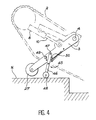
- FIG. 4 A simplified embodiment of the invention is shown in FIG. 4. It makes it possible to dispense with the hydraulic system described above and in particular of the solenoid valves 18 and 19 and of the limiters 20 and 21.
- a ground contact sensor 45 is used here.
- an articulated rod 46 by one end 47 to the arm 3, near the idler wheel 27.
- the other end of the connecting rod 46 carries a caster 48 which protrudes from the idler wheel 27 from below when the arm 3 is lifted from the ground. But when the arm 3 is deployed and on the point of reaching the bearing N, the contact of the caster 48 turns the connecting rod 46 which then comes to touch a switch 49.
- the movements of the arm 3 may depend solely on the progressive distributor 15 which is then slaved to the switch 49 or controlled by the driver, if there is one, using the indications of the switch 49 displayed on the dashboard.
- the progressive distributor 15 is controlled so that the flow rate which passes through it is reduced or eliminated. This avoids excessive deployments of the arm 3.
- a protruding cleat 50 of the arm 3 serves as a rotational stop for the connecting rod 46 and prevents it from hanging vertically.
- This embodiment of the invention can be combined with the previous one on the same vehicle.
Abstract
Description
L'invention se rapporte à un système de commande d'un bras mobile dépendant d'un véhicule et utilisé pour le franchissement de crêtes et a notamment été prévue pour être utilisée sur le véhicule décrit dans le brevet français de numéro d'enregistrement 87 02098.The invention relates to a control system of a mobile arm dependent on a vehicle and used for crossing ridges and has in particular been designed to be used on the vehicle described in the French patent with registration number 87 02098 .
Ce brevet décrit un véhicule à chenilles déplaçable sur des sols en pentes variables ; les crêtes sont définies comme des raccordements de pentes différentes délimitant des saillies. Dans l'application plus précisément envisagée, le véhicule se déplace sur des paliers et des escaliers, et les crêtes sont alors les raccordements d'un escalier et d'un palier supérieur.This patent describes a tracked vehicle that can be moved on floors with variable slopes; the crests are defined as connections of different slopes delimiting projections. In the application more precisely envisaged, the vehicle travels on landings and stairs, and the ridges are then the connections of a staircase and an upper landing.
Quand le véhicule commence à surplomber le palier après avoir gravi l'escalier et se trouve sur le point de basculer, on déploie le bras à l'avant du véhicule jusqu'à lui faire toucher le sol à une extrémité et on le ramène petit à petit en position rétractée au cours de l'avance subséquente du véhicule pour que ce dernier ne retombe que progressivement en position horizontale. Le bras est également déployé quand le véhicule est sur le point d'arriver sur un escalier descendant : le véhicule est porté à une inclinaison égale ou en pratique un peu supérieure à celle de l'escalier. On évite ainsi tout basculement brusque et, quand le centre de gravité du véhicule surplombe l'escalier, le bras peut être replié.When the vehicle begins to overhang the landing after having climbed the stairs and is about to tip over, you extend the arm at the front of the vehicle until it touches the ground at one end and it is brought back to small in the retracted position during the subsequent advance of the vehicle so that the latter only gradually falls back into the horizontal position. The arm is also deployed when the vehicle is about to arrive on a descending staircase: the vehicle is brought to an inclination equal to or in practice a little greater than that of the staircase. This avoids any sudden tilting and, when the center of gravity of the vehicle overhangs the staircase, the arm can be folded.
La principale critique que l'on puisse adresser à un tel système est son manque de précision. En effet, lors de la montée d'un escalier, on commande un déploiement total du bras sans pouvoir connaître avec précision l'instant approprié. Il s'ensuit soit que le véhicule est soulevé de l'escalier et incliné excessivement lorsque le déploiement est prématuré, ce qui compromet sa stabilité, soit que le bras n'atteint pas le palier dans le cas contraire, et un basculement brusque du véhicule ne peut être empêché.The main criticism that can be made of such a system is its lack of precision. Indeed, when climbing a staircase, a total deployment of the arm is commanded without being able to know with precision the appropriate instant. It follows either that the vehicle is lifted from the stairs and tilted excessively when the deployment is premature, which compromises its stability, or that the arm does not reach the landing otherwise, and a sudden tilting of the vehicle cannot be prevented.
On n'est en outre pas maître de la vitesse de rétraction du bras qui est ensuite provoquée.We are also not master of the speed of retraction of the arm which is then caused.
Le véhicule est également incliné excessivement quand il aborde un escalier descendant, et aucun moyen de réglage du déploiement du bras n'est indiqué dans ce brevet antérieur.The vehicle is also tilted excessively when it approaches a descending staircase, and no means of adjusting the deployment of the arm is indicated in this prior patent.
On remarquera enfin que, comme le bras est commandé par un système qui n'autorise qu'un état déployé stable, l'utilisation du véhicule est limitée à des trajets ne comportant que des variations de pente de même angle.Finally, it will be noted that, as the arm is controlled by a system which only allows a stable deployed state, the use of the vehicle is limited to journeys comprising only slope variations of the same angle.
L'invention décrite ci-après vise à résoudre ces problèmes et avant tout à rendre le franchissement de crêtes et la remise à l'horizontale plus doux en empêchant les déploiements excessifs du bras. Certaines variantes de l'invention permettent de plus de ne pas rétracter le bras trop vite ou de limiter l'inclinaison du véhicule au cours de la descente. L'invention est enfin utilisable sur des trajets comprenant par exemple des pentes ou des escaliers d'inclinaisons différentes.The invention described below aims to solve these problems and above all to make the crossing of ridges and the return to horizontal smoother by preventing excessive deployments of the arm. Certain variants of the invention also make it possible not to retract the arm too quickly or to limit the inclination of the vehicle during the descent. Finally, the invention can be used on routes comprising, for example, slopes or stairs of different inclinations.
L'invention est ainsi greffée sur un système de commande d'un bras mobile déplacé entre une position rétractée et une position déployée par des mouvements en sens opposés, le bras étant dépendant d'un véhicule évoluant sur un sol comportant des pentes variables séparées par des crêtes, la position rétractée correspondant à un état où le bras est soulevé du sol et la position déployée à un état où une extrémité inférieure du bras est dirigée vers le sol, comprenant un vérin composé d'un cylindre rempli de liquide, d'un piston coulissant dans le cylindre et le séparant en deux chambres étanches, d'une tige reliée au piston et au bras, une source de liquide sous pression et un réservoir de liquide, deux conduites aboutissant chacune à une chambre respective, un distributeur à trois états apte à bloquer les deux conduites et à raccorder chacune d'elles à la source de liquide sous pression, l'autre conduite étant alors raccordée au réservoir de liquide. Elle consiste à adjoindre à ce système des moyens pour arrëter le déploiement du bras quand son extrémité libre arrive au sol. Dans une réalisation, ces moyens consistent en une dérivation reliant une première chambre, dont le volume s'accroît quand le bras est déplacé vers la position déployée, au réservoir de liquide par l'intermédiaire d'un limiteur d'écoulement, une seconde dérivation reliant la seconde chambre au réservoir de liquide, et un système de distribution pour ouvrir et obturer les deux dérivations.The invention is thus grafted onto a control system for a movable arm moved between a retracted position and a position deployed by movements in opposite directions, the arm being dependent on a vehicle moving on a ground having variable slopes separated by ridges, the retracted position corresponding to a state where the arm is raised from the ground and the deployed position to a state where a lower end of the arm is directed towards the ground, comprising a jack composed of a cylinder filled with liquid, a piston sliding in the cylinder and separating it into two sealed chambers, a rod connected to the piston and to the arm, a source of pressurized liquid and a liquid reservoir, two pipes each leading to a respective chamber, a distributor with three states capable of blocking the two pipes and of connecting each of them to the source of pressurized liquid, the other pipe then being connected to the liquid tank. It consists in adding to this system means to stop the deployment of the arm when its free end reaches the ground. In one embodiment, these means consist of a bypass connecting a first chamber, the volume of which increases when the arm is moved towards the deployed position, to the liquid reservoir via a flow limiter, a second bypass connecting the second chamber to the liquid tank, and a distribution system to open and close the two branches.
La seconde dérivation est avantageusement munie d'un limiteur de débit. Le système peut également comporter un détecteur d'inclinaison fixé sur le véhicule et des moyens logiques comparant l'inclinaison du véhicule mesurée par le détecteur et une inclinaison de référence et ordonnant des déplacements partiels du bras en direction de sa position rétractée quand l'inclinaison du véhicule excède l'inclinaison de référence.The second bypass is advantageously provided with a flow limiter. The system may also include an inclination detector fixed to the vehicle and logic means comparing the inclination of the vehicle measured by the detector and a reference inclination and ordering partial movements of the arm towards its retracted position when the inclination of the vehicle exceeds the reference tilt.
Une réalisation plus simple de l'invention utilise un capteur de contact du sol qui comprend une partie reliée au bras de manière mobile et aboutissant au-dessous de l'extrémité libre du bras, ainsi qu'un interrupteur commuté lorsque la partie mobile est déplacée par contact du sol.A simpler embodiment of the invention uses a ground contact sensor which comprises a part connected to the arm in a mobile manner and ending below the free end of the arm, as well as a switch switched when the mobile part is moved by contact with the ground.
On va maintenant décrire plus en détail l'invention à l'aide des quatre figures suivantes annexées à titre illustratif et non limitatif :
- - La figure 1 est une vue générale d'une première réalisation de l'invention ;
- - La figure 2 montre une réalisation équivalente à celle de la figure 1 ;
- - La figure 3 montre un système utilisé pour commander le fonctionnement du bras au cours d'une descente ; et
- - La figure 4 illustre une autre réalisation.
- - Figure 1 is a general view of a first embodiment of the invention;
- - Figure 2 shows an embodiment equivalent to that of Figure 1;
- - Figure 3 shows a system used to control the operation of the arm during a descent; and
- - Figure 4 illustrates another embodiment.
Le véhicule, référencé par 1 sur la figure 1, est composé en particulier de deux chenilles 2 et d'un bras 3 pivotant autour d'une articulation 4 fixée sur le véhicule 1 entre une position déployée indiquée par la ligne 5 et une position rétractée indiquée par la ligne 6. Le pivotement du bras 3 est commandé par un vérin 7 constitué classiquement d'un cylindre 8 dans lequel coulisse un piston 9, auquel est liée une tige 10 qui traverse le cylindre 8 et aboutit par une articulation 28 à mi-longueur du bras 3. L'intérieur du cylindre 8 est divisé de manière étanche en une première chambre 11 ou chambre de fond, dont le volume s'accroït quand le bras 3 est déplacé vers sa position déployée, et une seconde chambre 12 par le piston 9. Une première conduite 13 et une seconde conduite 14 relient respectivement les première et seconde chambres 11 et 12 à un distributeur progressif 15 commandé électromagnétiquement, muni de ressorts de rappel et pouvant prendre trois états fondamentaux.The vehicle, referenced by 1 in FIG. 1, is composed in particular of two tracks 2 and of an
Le distributeur progressif 15 est également relié à une source d'huile sous pression P et à une bache à huile B. Quand il n'est pas commandé, il est fermé et obture les première et seconde conduites 13 et 14 ; quand il est commandé, il peut prendre deux états ouverts où il relie l'une ou l'autre des conduites 13 et 14 à la source d'huile sous pression P et l'autre conduite à la bâche B, créant ainsi dans les chambres 11 et 12 une différence de pression qui déplace le piston 9 et le bras 3 à une vitesse qui dépend de l'intensité du courant qui traverse les moyens électromagnétiques de commande du distributeur progressif 15 et l'ouvre donc plus ou moins.The
Deux dérivations 16 et 17 relient respectivement les deux chambres 11 et 12 ou, comme représenté ici, leurs conduites associées 13 et 14 à la bache B. Un système de distribution permet d'obturer ou d'ouvrir simultanément les deux dérivations 16 et 17. Dans le cas présent, on emploie deux distributeurs identiques 18 et 19 à commande électromagnétique et rappel par ressorts. A l'état non excité, les dérivations 16 et 17 sont obturées.Two
La première dérivation 16 est munie d'un limiteur de pression 20 qui n'autorise l'écoulement d'huile de la première chambre 11 vers la bache B qu'au-dessus d'une pression déterminée qui peut d'ailleurs être réglée par l'utilisateur en modifiant le tarage du ressort de rappel 26 du limiteur de pression 20. La seconde dérivation 17 est munie d'un limiteur de débit 21. Des bipasses 22 et 23 contournent respectivement le limiteur de pression 20 et le distributeur 18 d'une part, le limiteur de débit 21 d'autre part ; chacun des bipasses 22 et 23 est muni d'un clapet anti-retour 24 et 25 qui n'y autorise l'écoulement qu'à partir de la bache B vers la chambre associée 11 ou 12.The
Quand le véhicule finit de gravir un escalier E et commence à franchir la crête CR qui correspond en fait au nez de la marche la plus élevée pour surplomber un palier N, le bras 3, qui avait précédemment été ramené en position rétractée 6, est déployé. On excite pour cela les deux distributeurs 18 et 19 tout en maintenant le distributeur progressif 15 à l'état non excité. Le bras 3 tombe sous l'effet de la gravité, l'huile s'écoulant de la bâche B vers la première chambre 11 par le premier bipasse 22 et de la seconde chambre 12 vers la bâche B par la seconde dérivation 17. Ce second écoulement est toutefois freiné par le limiteur de débit 21, si bien que la descente du bras 3 se poursuit à vitesse modérée jusqu'à ce qu'une roue folle 27 à l'extrémité libre du bras 3 atteigne le palier N et que le centre de gravité du véhicule 1 arrive à l'aplomb de la crête CR. Le véhicule 1 commence alors à retomber et le bras 3 revient vers la position rétractée 6, mais ce mouvement est lui aussi progressif car l'écoulement de la première chambre 11 vers la bâche B qui s'instaure alors est freiné par le limiteur de pression 20. Il est avantageux de régler le limiteur de pression 20 de sorte qu'il n'autorise des écoulements qu'à une pression légèrement inférieure à la pression exercée par le piston 9 dans la première chambre 11 par le poids du véhicule 1 supporté par le bras 3. On est alors en régime quasi statique.When the vehicle finishes climbing a staircase E and begins to cross the crest CR which in fact corresponds to the nose of the highest step to overhang a level N, the
Le mouvement du bras 3 s'arrête quand le véhicule 1 est redevenu horizontal et ne porte plus que sur ses chenilles 2. L'excitation des distributeurs 18 et 19 cesse et le distributeur progressif 15 est excité pour ramener le bras 3 en position rétractée 6.The movement of the
Suivant une conception légèrement différente représentée figure 2, les bipasses 22 et 23 sont sup primés de même que le limiteur de débit 21. Les distributeurs 18 et 19 sont par ailleurs remplacés par un distributeur unique à deux voies 29 à commande électromagnétique et moyens de rappel qui, ici encore, ouvre les dérivations 16 et 17 à l'état excité et les ferme le reste du temps.According to a slightly different design shown in Figure 2, the
Une sous-dérivation 30 relie la source d'huile sous pression P à un point de la première dérivation 16 situé entre le distributeur à deux voies 29 et le limiteur de pression 20. La sous-dérivation 30 est munie d'un réducteur de pression 31 et d'un clapet unidirectionnel 32 qui n'autorise l'écoulement que vers la première chambre 11.A
L'utilisation d'un distributeur à deux voies 29 amène une simplification du dispositif. La sous-dérivation 30 permet par ailleurs d'introduire plus rapidement de l'huile dans la première chambre 11 et donc d'accélérer le déploiement du bras 3 sans toutefois le rendre trop brusque. Le clapet 32 empêche les retours d'huile vers le réducteur de pression 31 quand le véhicule 1 retombe.The use of a two-
Sur un palier N, le bras 3 donne au véhicule une inclinaison qui est de 17° dans la réalisation construite quand il est dans la position déployée 5 et les escaliers E qu'il faut descendre ont une pente moyenne de 27°. Comme le représente la figure 3, quand le véhicule s'apprête à descendre un escalier E, il ne porte cependant sur celui-ci que par sa partie éloignée du bras 3 (encore en appui sur le palier N) et prend donc une inclinaison supérieure à la pente de l'escalier E, ce qui met en danger sa stabilité. C'est pourquoi le véhicule 1 porte un système qui comprend un détecteur d'inclinaison ou inclinomètre 36 et un générateur d'inclinaison de référence 37. L'inclinomètre 36 fournit une tension proportionnelle à l'inclinaison du véhicule 1 et le générateur d'inclinaison de référence 37 une autre tension proportionnelle à la valeur de référence par un convertisseur 38. Un comparateur 39 permet de soustraire ces deux tensions et d'agir sur le distributeur progressif via un amplificateur 40.On a level N, the
Quand le véhicule 1 aborde donc un escalier E descendant, la valeur de l'inclinaison de référence est établie à une valeur légèrement supérieure à la pente moyenne de l'escalier (28° dans le cas présent) et, dès que l'inclinomètre 36 relève une valeur égale ou supérieure, le distributeur progressif 15 est excité de manière à faire pénétrer de l'huile dans la seconde chambre 12 pour rétracter légèrement le bras 3.When the vehicle 1 therefore approaches a descending staircase E, the value of the reference inclination is established at a value slightly greater than the average slope of the staircase (28 ° in this case) and, as soon as the
On rétracte ainsi progressivement le bras 3 jusqu'à ce que l'inclinomètre 36 relève une inclinaison au plus égale à 28°. La rétraction du bras 3 est reprise dès que l'inclinomètre 36 marque de nouveau une indication excédant cette valeur. Quand l'inclinaison du véhicule 1 reste stationnaire à 27°, ses chenilles 2 reposent sur l'escalier E sur toute leur longueur et le bras 3 peut être entièrement rétracté.The
Pendant ce processus, les autres distributeurs 18, 19 et 29 ne sont pas excités.During this process, the
Le générateur d'inclinaison de référence 37, de même que les distributeurs 18, 19 et 29, peut être commandé par le conducteur ou par des capteurs de variation de pente du sol tels que ceux mentionnés dans le brevet antérieur précité.The
Une réalisation simplifiée de l'invention est représentée sur la figure 4. Elle permet de se passer du système hydraulique décrit précédemment et en particulier des électrovannes 18 et 19 et des limiteurs 20 et 21. On utilise ici un capteur de contact du sol 45 constitué d'une bielle 46 articulée par une extrémité 47 au bras 3, près de la roue folle 27. L'autre extrémité de la bielle 46 porte une roulette 48 qui dépasse de la roue folle 27 par le bas quand le bras 3 est soulevé du sol. Mais quand le bras 3 est déployé et sur le point d'atteindre le palier N, le contact de la roulette 48 fait tourner la bielle 46 qui vient alors toucher un interrupteur 49. Dans cette réalisation, les mouvements du bras 3 peuvent dépendre uniquement du distributeur progressif 15 qui est alors asservi à l'interrupteur 49 ou commandé par le conducteur, s'il y en a un, à l'aide des indications de l'interrupteur 49 affichées sur le tableau de bord. Quand le contact de la roulette 48 sur le palier N est repéré, le distributeur progressif 15 est commandé pour que le débit qui le traverse soit réduit ou supprimé. On évite ainsi des déploiements excessifs du bras 3.A simplified embodiment of the invention is shown in FIG. 4. It makes it possible to dispense with the hydraulic system described above and in particular of the
Par ailleurs, des rétractions lentes du bras 3 restent possibles si on prend soin de n'exciter ensuite que légèrement le distributeur 15.Furthermore, slow retractions of the
Un taquet 50 saillant du bras 3 sert de butée en rotation à la bielle 46 et l'empêche de pendre verticalement.A protruding
Cette réalisation de l'invention peut être cumulée avec la précédente sur un même véhicule.This embodiment of the invention can be combined with the previous one on the same vehicle.
Claims (10)
Applications Claiming Priority (2)
| Application Number | Priority Date | Filing Date | Title |
|---|---|---|---|
| FR8913156A FR2652925B1 (en) | 1989-10-09 | 1989-10-09 | VEHICLE-DEPENDENT MOBILE ARM CONTROL SYSTEM USED FOR CROSS CROSSING. |
| FR8913156 | 1989-10-09 |
Publications (2)
| Publication Number | Publication Date |
|---|---|
| EP0423013A1 true EP0423013A1 (en) | 1991-04-17 |
| EP0423013B1 EP0423013B1 (en) | 1995-02-01 |
Family
ID=9386206
Family Applications (1)
| Application Number | Title | Priority Date | Filing Date |
|---|---|---|---|
| EP90402792A Expired - Lifetime EP0423013B1 (en) | 1989-10-09 | 1990-10-08 | System for controlling a movable lever arm articulated to a vehicle for crossing ridges |
Country Status (4)
| Country | Link |
|---|---|
| EP (1) | EP0423013B1 (en) |
| AT (1) | ATE117957T1 (en) |
| DE (1) | DE69016566D1 (en) |
| FR (1) | FR2652925B1 (en) |
Cited By (7)
| Publication number | Priority date | Publication date | Assignee | Title |
|---|---|---|---|---|
| KR100811860B1 (en) | 2006-08-18 | 2008-03-10 | 한양대학교 산학협력단 | The obstacle zone conquest robot |
| ITTO20100071A1 (en) * | 2010-02-02 | 2011-08-03 | Oto Melara Spa | DEVICE FOR DAMPING OF SUBSTANCES OF A CRAWLER VEHICLE AND ASSOCIATED TRACKED VEHICLE. |
| EP2436012A1 (en) * | 2009-05-27 | 2012-04-04 | R. Brooks Associates, Inc. | Steam generator upper bundle inspection tools |
| WO2014138439A1 (en) * | 2013-03-06 | 2014-09-12 | Massachusetts Institute Of Technology | Discrete motion system |
| CN110328651A (en) * | 2019-07-29 | 2019-10-15 | 东北大学 | Towards old man can obstacle detouring accompany and attend to robot |
| CN111572672A (en) * | 2020-06-01 | 2020-08-25 | 武义普巴机械设备有限公司 | Automatic loading and unloading transport vehicle capable of climbing stairs |
| KR102318510B1 (en) * | 2021-03-10 | 2021-10-27 | 박찬웅 | Unit for overcoming obstacle and caterpillar apparatus having the same |
Families Citing this family (1)
| Publication number | Priority date | Publication date | Assignee | Title |
|---|---|---|---|---|
| WO2021155465A1 (en) * | 2020-02-04 | 2021-08-12 | Movex Innovation Inc. | Inclination control system for tracked vehicle |
Citations (2)
| Publication number | Priority date | Publication date | Assignee | Title |
|---|---|---|---|---|
| WO1987002634A1 (en) * | 1985-10-29 | 1987-05-07 | The Secretary Of State For Defence In Her Britanni | Obstacle surmounting aid for tracked vehicle |
| FR2610885A1 (en) * | 1987-02-18 | 1988-08-19 | Protee | Motorised vehicle with caterpillar tracks with articulated arms for negotiating obstacles |
Family Cites Families (1)
| Publication number | Priority date | Publication date | Assignee | Title |
|---|---|---|---|---|
| JPS5920777A (en) * | 1982-07-24 | 1984-02-02 | Furukawa Mining Co Ltd | Transport vehicle |
-
1989
- 1989-10-09 FR FR8913156A patent/FR2652925B1/en not_active Expired - Fee Related
-
1990
- 1990-10-08 DE DE69016566T patent/DE69016566D1/en not_active Expired - Lifetime
- 1990-10-08 AT AT90402792T patent/ATE117957T1/en not_active IP Right Cessation
- 1990-10-08 EP EP90402792A patent/EP0423013B1/en not_active Expired - Lifetime
Patent Citations (2)
| Publication number | Priority date | Publication date | Assignee | Title |
|---|---|---|---|---|
| WO1987002634A1 (en) * | 1985-10-29 | 1987-05-07 | The Secretary Of State For Defence In Her Britanni | Obstacle surmounting aid for tracked vehicle |
| FR2610885A1 (en) * | 1987-02-18 | 1988-08-19 | Protee | Motorised vehicle with caterpillar tracks with articulated arms for negotiating obstacles |
Non-Patent Citations (1)
| Title |
|---|
| PATENT ABSTRACTS OF JAPAN, vol. 8, no. 112 (M-298)[1549], 25 mai 1984; & JP-A-59 20 777 (FURUKAWA KOGYO K.K.) 02-02-1984 * |
Cited By (11)
| Publication number | Priority date | Publication date | Assignee | Title |
|---|---|---|---|---|
| KR100811860B1 (en) | 2006-08-18 | 2008-03-10 | 한양대학교 산학협력단 | The obstacle zone conquest robot |
| EP2436012A1 (en) * | 2009-05-27 | 2012-04-04 | R. Brooks Associates, Inc. | Steam generator upper bundle inspection tools |
| EP2436012A4 (en) * | 2009-05-27 | 2014-03-19 | Brooks R Ass Inc | Steam generator upper bundle inspection tools |
| US9251921B2 (en) | 2009-05-27 | 2016-02-02 | R. Brooks Associates, Inc. | Steam generator upper bundle inspection tools |
| EP3147910A1 (en) * | 2009-05-27 | 2017-03-29 | Rolls-Royce Nuclear Field Services Inc. | A vehicular inspection system for inspecting a secondary side of a steam generator |
| ITTO20100071A1 (en) * | 2010-02-02 | 2011-08-03 | Oto Melara Spa | DEVICE FOR DAMPING OF SUBSTANCES OF A CRAWLER VEHICLE AND ASSOCIATED TRACKED VEHICLE. |
| EP2353975A1 (en) * | 2010-02-02 | 2011-08-10 | Oto Melara S.p.A. | Device for damping out of bumps in a tracked vehicle and an associated tracked vehicle |
| WO2014138439A1 (en) * | 2013-03-06 | 2014-09-12 | Massachusetts Institute Of Technology | Discrete motion system |
| CN110328651A (en) * | 2019-07-29 | 2019-10-15 | 东北大学 | Towards old man can obstacle detouring accompany and attend to robot |
| CN111572672A (en) * | 2020-06-01 | 2020-08-25 | 武义普巴机械设备有限公司 | Automatic loading and unloading transport vehicle capable of climbing stairs |
| KR102318510B1 (en) * | 2021-03-10 | 2021-10-27 | 박찬웅 | Unit for overcoming obstacle and caterpillar apparatus having the same |
Also Published As
| Publication number | Publication date |
|---|---|
| EP0423013B1 (en) | 1995-02-01 |
| DE69016566D1 (en) | 1995-03-16 |
| ATE117957T1 (en) | 1995-02-15 |
| FR2652925A1 (en) | 1991-04-12 |
| FR2652925B1 (en) | 1994-02-18 |
Similar Documents
| Publication | Publication Date | Title |
|---|---|---|
| FR2691187A1 (en) | Method for automatically controlling the orientation motor of an excavator. | |
| EP0423013B1 (en) | System for controlling a movable lever arm articulated to a vehicle for crossing ridges | |
| FR2639016A1 (en) | STABILIZATION DEVICE FOR TILTING VEHICLE | |
| EP1215091A2 (en) | Device for immobilizing the legs of a passenger in a seat | |
| EP1399357B1 (en) | Articulated vehicle | |
| FR2715119A1 (en) | Improved autoguiding arm of a road vehicle along a steering rail. | |
| EP0389378B1 (en) | Vehicle loading platform and method of using same | |
| EP0045697A1 (en) | Hydraulic apparatus permitting the disconnection of a fluid-transferring articulated arm, especially for an urgent disconnection | |
| FR2487803A1 (en) | IMPROVEMENTS IN CABLE LIFTING APPARATUS, SUCH AS LIFT BRIDGES | |
| FR2473029A1 (en) | FORWARD BRIDGE, CONVEYOR OR TILT, HYDRAULICALLY ACTUATED | |
| EP3816091B1 (en) | Tower crane with automatic folding and unfolding stanchion | |
| EP0041901B1 (en) | Gripping device for containers or similar objects comprising level detectors | |
| FR2598142A1 (en) | FORK LIFT TRUCK WITH AN ORIENTABLE CONTROL BLOCK AND A MOBILE HEAD CARRIER ASSEMBLY. | |
| FR2470079A1 (en) | Hoist for lifting asymmetric loads - has balancing hoist controlling sling position through sensing switches | |
| FR2496613A2 (en) | APPARATUS FOR RECOVERING BULK MATERIALS | |
| FR2484929A1 (en) | RETRACTABLE PANTOGRAPH IN CASE OF ABNORMAL FRONT EFFORT | |
| WO1997000803A1 (en) | Retractable device for stabilising a stationary two-wheeled motor vehicle, and method therefor | |
| EP3932505A1 (en) | Passenger restraint system for roller coasters | |
| EP3705364A1 (en) | Vehicle stabiliser | |
| FR2877657A1 (en) | Elevating platform system for person with reduced mobility, has roller supporting on rail to control motor and pushing unit to displace platform, carried by vertical apron, from lower to upper position along slope of staircase | |
| FR2503055A1 (en) | Adjustable height hydraulic suspension for motor vehicles - uses combined height adjuster and damper unit controlled by electrically operated hydraulic pressure fluid distributor valve | |
| EP1348666A1 (en) | Oil delivery system in the equilibration circuit of a variable reach jib crane | |
| FR2655131A1 (en) | Device for adjusting and maintaining the attitude of a vertically movable support | |
| FR2877656A1 (en) | Elevating platform system for mobility impaired person, has frame fixed to ground, at staircase base, before initial stair, and laterally with respect to staircase`s passage zone, and control unit assuring horizontal position of apron | |
| BE1001764A3 (en) | CHASSIS HEIGHT CONTROL SYSTEM FOR A PNEUMATIC SUSPENSION VEHICLE. |
Legal Events
| Date | Code | Title | Description |
|---|---|---|---|
| PUAI | Public reference made under article 153(3) epc to a published international application that has entered the european phase |
Free format text: ORIGINAL CODE: 0009012 |
|
| AK | Designated contracting states |
Kind code of ref document: A1 Designated state(s): AT BE CH DE ES GB GR IT LI LU NL SE |
|
| 17P | Request for examination filed |
Effective date: 19910920 |
|
| 17Q | First examination report despatched |
Effective date: 19930407 |
|
| GRAA | (expected) grant |
Free format text: ORIGINAL CODE: 0009210 |
|
| AK | Designated contracting states |
Kind code of ref document: B1 Designated state(s): AT BE CH DE ES GB GR IT LI LU NL SE |
|
| PG25 | Lapsed in a contracting state [announced via postgrant information from national office to epo] |
Ref country code: IT Free format text: LAPSE BECAUSE OF FAILURE TO SUBMIT A TRANSLATION OF THE DESCRIPTION OR TO PAY THE FEE WITHIN THE PRESCRIBED TIME-LIMIT;WARNING: LAPSES OF ITALIAN PATENTS WITH EFFECTIVE DATE BEFORE 2007 MAY HAVE OCCURRED AT ANY TIME BEFORE 2007. THE CORRECT EFFECTIVE DATE MAY BE DIFFERENT FROM THE ONE RECORDED. Effective date: 19950201 Ref country code: GB Effective date: 19950201 Ref country code: GR Free format text: LAPSE BECAUSE OF FAILURE TO SUBMIT A TRANSLATION OF THE DESCRIPTION OR TO PAY THE FEE WITHIN THE PRESCRIBED TIME-LIMIT Effective date: 19950201 Ref country code: ES Free format text: THE PATENT HAS BEEN ANNULLED BY A DECISION OF A NATIONAL AUTHORITY Effective date: 19950201 Ref country code: NL Effective date: 19950201 Ref country code: AT Effective date: 19950201 |
|
| REF | Corresponds to: |
Ref document number: 117957 Country of ref document: AT Date of ref document: 19950215 Kind code of ref document: T |
|
| REF | Corresponds to: |
Ref document number: 69016566 Country of ref document: DE Date of ref document: 19950316 |
|
| PG25 | Lapsed in a contracting state [announced via postgrant information from national office to epo] |
Ref country code: SE Effective date: 19950501 |
|
| PG25 | Lapsed in a contracting state [announced via postgrant information from national office to epo] |
Ref country code: DE Effective date: 19950503 |
|
| NLV1 | Nl: lapsed or annulled due to failure to fulfill the requirements of art. 29p and 29m of the patents act | ||
| GBV | Gb: ep patent (uk) treated as always having been void in accordance with gb section 77(7)/1977 [no translation filed] |
Effective date: 19950201 |
|
| PG25 | Lapsed in a contracting state [announced via postgrant information from national office to epo] |
Ref country code: LI Effective date: 19951031 Ref country code: BE Effective date: 19951031 Ref country code: CH Effective date: 19951031 Ref country code: LU Free format text: LAPSE BECAUSE OF NON-PAYMENT OF DUE FEES Effective date: 19951031 |
|
| PLBE | No opposition filed within time limit |
Free format text: ORIGINAL CODE: 0009261 |
|
| STAA | Information on the status of an ep patent application or granted ep patent |
Free format text: STATUS: NO OPPOSITION FILED WITHIN TIME LIMIT |
|
| 26N | No opposition filed | ||
| BERE | Be: lapsed |
Owner name: PROTEE GROUPEMENT D'INTERET ECONOMIQUE Effective date: 19951031 |
|
| REG | Reference to a national code |
Ref country code: CH Ref legal event code: PL |