EP0422802A1 - Dispositif de codage/décodage de parole - Google Patents
Dispositif de codage/décodage de parole Download PDFInfo
- Publication number
- EP0422802A1 EP0422802A1 EP90310587A EP90310587A EP0422802A1 EP 0422802 A1 EP0422802 A1 EP 0422802A1 EP 90310587 A EP90310587 A EP 90310587A EP 90310587 A EP90310587 A EP 90310587A EP 0422802 A1 EP0422802 A1 EP 0422802A1
- Authority
- EP
- European Patent Office
- Prior art keywords
- codewords
- control signal
- decoder
- preferred
- arrangement according
- Prior art date
- Legal status (The legal status is an assumption and is not a legal conclusion. Google has not performed a legal analysis and makes no representation as to the accuracy of the status listed.)
- Withdrawn
Links
Images

Classifications
-
- H—ELECTRICITY
- H04—ELECTRIC COMMUNICATION TECHNIQUE
- H04L—TRANSMISSION OF DIGITAL INFORMATION, e.g. TELEGRAPHIC COMMUNICATION
- H04L1/00—Arrangements for detecting or preventing errors in the information received
- H04L1/004—Arrangements for detecting or preventing errors in the information received by using forward error control
- H04L1/0056—Systems characterized by the type of code used
- H04L1/0061—Error detection codes
-
- H—ELECTRICITY
- H04—ELECTRIC COMMUNICATION TECHNIQUE
- H04B—TRANSMISSION
- H04B14/00—Transmission systems not characterised by the medium used for transmission
- H04B14/02—Transmission systems not characterised by the medium used for transmission characterised by the use of pulse modulation
- H04B14/06—Transmission systems not characterised by the medium used for transmission characterised by the use of pulse modulation using differential modulation, e.g. delta modulation
- H04B14/066—Transmission systems not characterised by the medium used for transmission characterised by the use of pulse modulation using differential modulation, e.g. delta modulation using differential modulation with several bits [NDPCM]
- H04B14/068—Transmission systems not characterised by the medium used for transmission characterised by the use of pulse modulation using differential modulation, e.g. delta modulation using differential modulation with several bits [NDPCM] with adaptive feedback
Definitions
- This invention relates to speech codec arrangements for muting a voice band signal when the error rate in an ADPCM channel exceeds a predetermined threshold.
- a speech codec arrangement includes means for detecting predetermined illegal codewords in a received coded bit stream, means for estimating the current bit error rate from the detection of illegal codewords, means for generating a control signal in response to a predetermined level of the estimated error rate, means for generating preferred codewords, and means responsive to said control signal to replace codewords with preferred codewords for the duration of the control signal.
- references to ADPCM codecs relate to Adaptive Differential PCM codecs with particular relevance to codecs conforming to the CCITT G721 standards.
- the ADPCM input to G721 decoder 10 is also fed to an illegal code detector 11 the output of which is applied to a muting control circuit 12.
- the arrangement exploits the fact that a code of '0000' should never be received by a G721 ADPCM decoder operating over an error free transmission channel.
- the muting control circuit 12 conveniently comprises a filter followed by a comparator.
- the filter output may be used directly as an indication of the current bit error rate. This output is then compared against a predetermined threshold to provide a muting control signal when the threshold is exceeded.
- the comparator may usefully have a defined amount of hysteresis to give the muting control circuit a minimum hangover time.
- the muting control signal is applied to control a multiplexer 13.
- the PCM output of the G721 decoder is fed as one input to the multiplexer.
- An idle code generator 14 provides the other input to the multiplexer.
- the multiplexer replaces the output of the decoder with idle codes. This method of operation of the muting process allows the decoder to operate as far as possible in synchronism with the encoder, because the ADPCM codes are still passed to the decoder even when the muting control is enabled.
- the muting control acts on the input to the G721 decoder.
- the incoming code stream is intercepted by the multiplexer 13 before it reaches the decoder.
- the arrangement acts to substitute idle code groups, i.e. '1111' for the incoming code words at the input to the decoder. This will cause the output of the ADPCM decoder to decay down to zero over a short period of time, typically a few milliseconds, but prevents any possibility of the decoder remaining roughly in synchronisation with the encoder.
- the filter and comparator circuits can be implemented in either analogue or digital circuitry.
- an RC low-pass filter with a suitable time constant can be used as an analogue filter, or a leaky integrator can be used as a digital filter.
- an operational amplifier with a small amount of positive feedback, or its digital equivalent, can be used as the comparator with hysteresis.
- control signals to mute the output signal from the ADPCM decoder after digital to analogue conversion. This is the approach adopted in the complete muter implementation shown in Fig. 3.
- the filter and comparator circuits can be implemented in either analogue or digital circuitry.
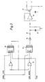
- An ADPCM muter is shown in Figure 3 and described below. It is assumed that the circuit is given serial ADPCM codewords, a serial clock, and a synchronising signal which goes high for one clock cycle immediately prior to the arrival of the ADPCM codeword.
- the synchronisation signal is used to clear two four-bit counters 30,31. The first of these counters 30 is arranged to mark the four bit periods immediately after the synchronisation signal, by connecting an inverted version of its Q2 output to its enable input EN. Thus when the counter 30 is cleared by the synchronisation signal at RST, Q2 goes low, and hence the enable goes high.
- the counter then starts to count upwards until a count of four is reached, at which point the enable input is forced low, and the count stops.
- the output Q2 is thus low solely for the duration of the four clock cycles after the synchronisation signal.
- the ADPCM codeword is combined with this marker signal by a two-input NOR gate 32, whose outputs will therefore be high if and only if the ADPCM data input is zero during the four clock cycles after the synchronisation signal.
- the resulting signal is used as an enable on the second counter 31, which will therefore count how many of the ADPCM bits are set to zero. Only if all four ADPCM data bits are zero will the Q2 output of the second counter 31 go high.
- the Q2 output of this counter 31 is fed through the resistor 33 and diode 34 network to a capacitor 35.
- This implements a fast attack, slow decay filter.
- the capacitor in turn is connected to a comparator 36, with hysteresis.
- the output of this comparator 36 possibly retimed by the ADPCM synchronisation word, is used as the muter control signal.
- the time constants and hysteresis level are chosen such that an isolated illegal code does not cause a mute, but that two such illegal codes within a short period, say 6 ms, would cause muting.
- the hysteresis guarantees a minimum hangover time for the mute condition, with 6 ms again being a reasonable minimum.
- the muter control signal is then used to control an analogue switch 37 such that the output from the digital to analogue converter which follows the ADPCM decoder is substantially reduced, typically by 30 dB, for the duration of the muter control signal.
- This has the advantage for cordless radio products that the listener will still hear the noise introduced by loss of the digital link, but at a comfortable level.
- the muter switch can be used to short across a high value resistor employed to control the gain of the digital-to-analogue converter (not shown).
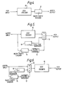
- Fig. 3 shows how the encoder in a G721 ADPCM codec can be modified by the addition of a block parity encoder.
- Parity checking is a well-known technique used for detecting errors in digital bit streams.
- the ADPCM code stream from the G721 encoder 20 is intercepted by the block parity encoder 21.
- the end of a block is defined by the occurrence of a '1111' code in the G721 encoder output. This '1111' code is transmitted if the parity of the block is even. If the parity of the block so far is odd then the '1111' code is replaced by a '0000' code.
- the incoming bit stream is intercepted by a block parity checker circuit 15, which considers blocks to be delimited by '0000'/'1111' codes. If code '0000' is considered to have odd parity then the parity of a block including the end marker should always be even, and a block which has odd parity is therefore a direct indication that an error has occurred within that block.
- the output of the block parity checker is applied to a muting control circuit 12 which estimates the current channel bit error rate and causes multiplexer 13 to insert idle codes in place of the output of the decoder 10 when the bit error rate is deemed to be too high.
- Fig. 6 corresponds to that of Fig. 2, wherein the codes will be inserted at the input to the ADPCM decoder whenever the muting control circuit indicates a period of high bit error rate.
- One final function performed by the block parity checker is to replace all '0000' codes by '1111' codes before passing them on to the ADPCM decoder, since they are not handled identically by the G721 ADPCM algorithm.
- the filter and comparator can be implemented as in the arrangements of Fig. 1 or 2, although for Fig. 5 or 6 it may be preferable to use a digital filter which is clocked only on incoming parity block boundaries. This would prevent the muting action from being removed should the time between successive '1111' codes become large at the ADPCM encoder output, as can happen during a loud speech burst.
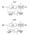
- simple muting can be replaced by a more elaborate arrangement employing variable attenuation such that the output signal level of the decoder reduces progressively as the error rate increases.
- This technique is illustrated in Figs. 7 and 8 which show modifications of Figs. 1 and 5 respectively.
- the output of the decoder 10 is progressively attenuated by the attenuator 21 as the estimated bit error rate determined via the rate estimation filter 22 increases. This gives the user more feedback than does a simple muting, for example about the location of radio nulls to be avoided in personal radio communications terminal applications.
Landscapes
- Engineering & Computer Science (AREA)
- Computer Networks & Wireless Communication (AREA)
- Signal Processing (AREA)
- Error Detection And Correction (AREA)
- Transmission Systems Not Characterized By The Medium Used For Transmission (AREA)
Applications Claiming Priority (2)
| Application Number | Priority Date | Filing Date | Title |
|---|---|---|---|
| GB8922962 | 1989-10-12 | ||
| GB8922962A GB2237484B (en) | 1989-10-12 | 1989-10-12 | Speech codec arrangement |
Publications (1)
| Publication Number | Publication Date |
|---|---|
| EP0422802A1 true EP0422802A1 (fr) | 1991-04-17 |
Family
ID=10664440
Family Applications (1)
| Application Number | Title | Priority Date | Filing Date |
|---|---|---|---|
| EP90310587A Withdrawn EP0422802A1 (fr) | 1989-10-12 | 1990-09-27 | Dispositif de codage/décodage de parole |
Country Status (4)
| Country | Link |
|---|---|
| EP (1) | EP0422802A1 (fr) |
| CA (1) | CA2026924A1 (fr) |
| FI (1) | FI904768A0 (fr) |
| GB (1) | GB2237484B (fr) |
Cited By (4)
| Publication number | Priority date | Publication date | Assignee | Title |
|---|---|---|---|---|
| EP0486232A2 (fr) * | 1990-11-12 | 1992-05-20 | Texas Instruments Incorporated | Décodeur MICDA à détection d'erreur |
| EP0634845A2 (fr) * | 1993-07-12 | 1995-01-18 | Motorola, Inc. | Détection des rafales de bruit dans un décodeur MICDA |
| WO1998015946A1 (fr) * | 1996-10-09 | 1998-04-16 | Ericsson, Inc. | Systemes et procedes de communication d'une information audio specifique par un support de communications |
| WO1999001941A1 (fr) * | 1997-07-02 | 1999-01-14 | Alcatel Alsthom - Compagnie Generale D'electricite | Dispositif de transmission d'un signal vocal code micda |
Families Citing this family (1)
| Publication number | Priority date | Publication date | Assignee | Title |
|---|---|---|---|---|
| JP2927242B2 (ja) * | 1996-06-28 | 1999-07-28 | 日本電気株式会社 | 音声符号データの誤り処理装置及び誤り処理方法 |
Citations (4)
| Publication number | Priority date | Publication date | Assignee | Title |
|---|---|---|---|---|
| GB1326562A (en) * | 1971-04-19 | 1973-08-15 | Gen Electric Co Ltd | Digital transmission systems |
| GB1369946A (en) * | 1973-05-10 | 1974-10-09 | Mel Equipment Co Ltd | Noise-muting device for telegraphy receivers |
| GB2025176A (en) * | 1978-06-30 | 1980-01-16 | Philips Nv | Reducing errors in digital transmission |
| DE3020257A1 (de) * | 1979-05-28 | 1981-01-29 | Hitachi Ltd | Rauschsperrenschaltung fuer pcm- aufzeichnungs- und -wiedergabegeraet |
Family Cites Families (1)
| Publication number | Priority date | Publication date | Assignee | Title |
|---|---|---|---|---|
| DE3537451A1 (de) * | 1985-10-22 | 1987-04-23 | Philips Patentverwaltung | Vermittlungsanlage mit fehlerkorrektur |
-
1989
- 1989-10-12 GB GB8922962A patent/GB2237484B/en not_active Expired - Fee Related
-
1990
- 1990-09-27 EP EP90310587A patent/EP0422802A1/fr not_active Withdrawn
- 1990-09-27 FI FI904768A patent/FI904768A0/fi not_active IP Right Cessation
- 1990-10-04 CA CA 2026924 patent/CA2026924A1/fr not_active Abandoned
Patent Citations (4)
| Publication number | Priority date | Publication date | Assignee | Title |
|---|---|---|---|---|
| GB1326562A (en) * | 1971-04-19 | 1973-08-15 | Gen Electric Co Ltd | Digital transmission systems |
| GB1369946A (en) * | 1973-05-10 | 1974-10-09 | Mel Equipment Co Ltd | Noise-muting device for telegraphy receivers |
| GB2025176A (en) * | 1978-06-30 | 1980-01-16 | Philips Nv | Reducing errors in digital transmission |
| DE3020257A1 (de) * | 1979-05-28 | 1981-01-29 | Hitachi Ltd | Rauschsperrenschaltung fuer pcm- aufzeichnungs- und -wiedergabegeraet |
Cited By (8)
| Publication number | Priority date | Publication date | Assignee | Title |
|---|---|---|---|---|
| EP0486232A2 (fr) * | 1990-11-12 | 1992-05-20 | Texas Instruments Incorporated | Décodeur MICDA à détection d'erreur |
| EP0486232A3 (en) * | 1990-11-12 | 1993-03-17 | Texas Instruments Incorporated | Adpcm decoder with error detection |
| EP0634845A2 (fr) * | 1993-07-12 | 1995-01-18 | Motorola, Inc. | Détection des rafales de bruit dans un décodeur MICDA |
| EP0634845A3 (fr) * | 1993-07-12 | 1995-03-08 | Motorola Inc | Détection des rafales de bruit dans un décodeur MICDA. |
| WO1998015946A1 (fr) * | 1996-10-09 | 1998-04-16 | Ericsson, Inc. | Systemes et procedes de communication d'une information audio specifique par un support de communications |
| US5954834A (en) * | 1996-10-09 | 1999-09-21 | Ericsson Inc. | Systems and methods for communicating desired audio information over a communications medium |
| AU723297B2 (en) * | 1996-10-09 | 2000-08-24 | Ericsson Inc. | Systems and methods for communicating desired audio information over a communications medium |
| WO1999001941A1 (fr) * | 1997-07-02 | 1999-01-14 | Alcatel Alsthom - Compagnie Generale D'electricite | Dispositif de transmission d'un signal vocal code micda |
Also Published As
| Publication number | Publication date |
|---|---|
| GB8922962D0 (en) | 1989-11-29 |
| GB2237484B (en) | 1994-01-12 |
| FI904768A0 (fi) | 1990-09-27 |
| GB2237484A (en) | 1991-05-01 |
| CA2026924A1 (fr) | 1991-04-13 |
Similar Documents
| Publication | Publication Date | Title |
|---|---|---|
| US4719642A (en) | Error detection and concealment using predicted signal values | |
| EP0397968B1 (fr) | Codeur-décodeur de parole | |
| US5799039A (en) | Method and apparatus for error mitigating a received communication signal | |
| US4800562A (en) | Circuit and method for monitoring the quality of data in a data stream | |
| US4167653A (en) | Adaptive speech signal detector | |
| AU650947B2 (en) | Digital communications systems | |
| EP0422802A1 (fr) | Dispositif de codage/décodage de parole | |
| EP1441460B1 (fr) | Dispositif suppresseur de bruit d'impulsion | |
| JPH0235502B2 (fr) | ||
| US4507792A (en) | PCM Encoder conformable to the A-law | |
| EP0486232A2 (fr) | Décodeur MICDA à détection d'erreur | |
| EP0574117B1 (fr) | Discrimination et suppression du bruit dans un signal de communication | |
| US4349707A (en) | System for measuring the attenuation on a transmission path | |
| GB1521091A (en) | Circuit arrangements for use in data transmission systems | |
| US6047036A (en) | System and method for implementing a mute voice signal upon reception of a ADPCM zero nibble in wireless communications | |
| AU2003200303B2 (en) | Reception of digitally coded protection signals in a remote tripping device | |
| EP1049304A4 (fr) | Systeme d'essai de controle de canal | |
| US3963878A (en) | Signal interpreting system for frequency selective multifrequency tone dialing | |
| JPH05183455A (ja) | 干渉波防止付き受信装置 | |
| US6052570A (en) | RSSI comparison circuit for a time duplex system | |
| US4862404A (en) | Digital circuit for suppressing fast signal variations | |
| GB2214760A (en) | A method of removing unwanted digital sequences from a communication system | |
| JP2544499B2 (ja) | 入力信号状態監視回路 | |
| JPS62144493A (ja) | 多周波信号受信器 | |
| JPS59125145A (ja) | プツシユホン信号送信装置及び受信装置 |
Legal Events
| Date | Code | Title | Description |
|---|---|---|---|
| PUAI | Public reference made under article 153(3) epc to a published international application that has entered the european phase |
Free format text: ORIGINAL CODE: 0009012 |
|
| AK | Designated contracting states |
Kind code of ref document: A1 Designated state(s): DE ES FR GB IT |
|
| 17P | Request for examination filed |
Effective date: 19910502 |
|
| 17Q | First examination report despatched |
Effective date: 19930209 |
|
| STAA | Information on the status of an ep patent application or granted ep patent |
Free format text: STATUS: THE APPLICATION IS DEEMED TO BE WITHDRAWN |
|
| 18D | Application deemed to be withdrawn |
Effective date: 19930622 |