EP0422267B1 - Méthode de nettoyage par variation pulsatoire de la pression - Google Patents
Méthode de nettoyage par variation pulsatoire de la pression Download PDFInfo
- Publication number
- EP0422267B1 EP0422267B1 EP19890118849 EP89118849A EP0422267B1 EP 0422267 B1 EP0422267 B1 EP 0422267B1 EP 19890118849 EP19890118849 EP 19890118849 EP 89118849 A EP89118849 A EP 89118849A EP 0422267 B1 EP0422267 B1 EP 0422267B1
- Authority
- EP
- European Patent Office
- Prior art keywords
- water
- pressure
- heat exchanger
- pressure pulse
- gas
- Prior art date
- Legal status (The legal status is an assumption and is not a legal conclusion. Google has not performed a legal analysis and makes no representation as to the accuracy of the status listed.)
- Expired - Lifetime
Links
- 238000000034 method Methods 0.000 title claims description 55
- 238000004140 cleaning Methods 0.000 title claims description 34
- 239000010802 sludge Substances 0.000 claims description 42
- 238000010304 firing Methods 0.000 claims description 33
- 230000035939 shock Effects 0.000 claims description 20
- 239000007788 liquid Substances 0.000 claims 6
- XLYOFNOQVPJJNP-UHFFFAOYSA-N water Substances O XLYOFNOQVPJJNP-UHFFFAOYSA-N 0.000 description 111
- 239000007789 gas Substances 0.000 description 55
- 238000000429 assembly Methods 0.000 description 20
- 230000000712 assembly Effects 0.000 description 20
- 230000008878 coupling Effects 0.000 description 8
- 238000010168 coupling process Methods 0.000 description 8
- 238000005859 coupling reaction Methods 0.000 description 8
- 238000009835 boiling Methods 0.000 description 6
- 239000008367 deionised water Substances 0.000 description 5
- 239000013618 particulate matter Substances 0.000 description 5
- 229910021641 deionized water Inorganic materials 0.000 description 4
- 238000001035 drying Methods 0.000 description 4
- 230000000694 effects Effects 0.000 description 4
- 230000008569 process Effects 0.000 description 4
- IJGRMHOSHXDMSA-UHFFFAOYSA-N Atomic nitrogen Chemical compound N#N IJGRMHOSHXDMSA-UHFFFAOYSA-N 0.000 description 3
- 230000007797 corrosion Effects 0.000 description 3
- 238000005260 corrosion Methods 0.000 description 3
- 238000007599 discharging Methods 0.000 description 3
- 238000011049 filling Methods 0.000 description 3
- 238000007689 inspection Methods 0.000 description 3
- 230000002093 peripheral effect Effects 0.000 description 3
- 229910001220 stainless steel Inorganic materials 0.000 description 3
- 239000010935 stainless steel Substances 0.000 description 3
- 230000002411 adverse Effects 0.000 description 2
- 230000008901 benefit Effects 0.000 description 2
- 238000004891 communication Methods 0.000 description 2
- 238000006073 displacement reaction Methods 0.000 description 2
- 238000001914 filtration Methods 0.000 description 2
- 239000012535 impurity Substances 0.000 description 2
- 238000002955 isolation Methods 0.000 description 2
- 238000012423 maintenance Methods 0.000 description 2
- 230000007246 mechanism Effects 0.000 description 2
- 239000002184 metal Substances 0.000 description 2
- 230000001376 precipitating effect Effects 0.000 description 2
- 239000008213 purified water Substances 0.000 description 2
- 230000002285 radioactive effect Effects 0.000 description 2
- 230000002829 reductive effect Effects 0.000 description 2
- 238000011160 research Methods 0.000 description 2
- 238000007789 sealing Methods 0.000 description 2
- 230000003068 static effect Effects 0.000 description 2
- 239000000725 suspension Substances 0.000 description 2
- 238000012360 testing method Methods 0.000 description 2
- 229940125725 tranquilizer Drugs 0.000 description 2
- 239000003204 tranquilizing agent Substances 0.000 description 2
- 230000002936 tranquilizing effect Effects 0.000 description 2
- 230000009471 action Effects 0.000 description 1
- 230000003466 anti-cipated effect Effects 0.000 description 1
- 230000001684 chronic effect Effects 0.000 description 1
- 150000001875 compounds Chemical class 0.000 description 1
- 230000001010 compromised effect Effects 0.000 description 1
- 238000005336 cracking Methods 0.000 description 1
- 238000005202 decontamination Methods 0.000 description 1
- 230000003588 decontaminative effect Effects 0.000 description 1
- 230000002939 deleterious effect Effects 0.000 description 1
- 238000000151 deposition Methods 0.000 description 1
- 229910001873 dinitrogen Inorganic materials 0.000 description 1
- 238000005516 engineering process Methods 0.000 description 1
- 239000010419 fine particle Substances 0.000 description 1
- 238000011010 flushing procedure Methods 0.000 description 1
- 239000011261 inert gas Substances 0.000 description 1
- 238000009434 installation Methods 0.000 description 1
- 230000002452 interceptive effect Effects 0.000 description 1
- 238000005342 ion exchange Methods 0.000 description 1
- SZVJSHCCFOBDDC-UHFFFAOYSA-N iron(II,III) oxide Inorganic materials O=[Fe]O[Fe]O[Fe]=O SZVJSHCCFOBDDC-UHFFFAOYSA-N 0.000 description 1
- 239000000463 material Substances 0.000 description 1
- 229910052757 nitrogen Inorganic materials 0.000 description 1
- 230000036961 partial effect Effects 0.000 description 1
- 239000002245 particle Substances 0.000 description 1
- 239000002244 precipitate Substances 0.000 description 1
- 230000001737 promoting effect Effects 0.000 description 1
- 230000010349 pulsation Effects 0.000 description 1
- 230000005855 radiation Effects 0.000 description 1
- 230000003134 recirculating effect Effects 0.000 description 1
- 239000000523 sample Substances 0.000 description 1
- 239000007787 solid Substances 0.000 description 1
- 239000000126 substance Substances 0.000 description 1
- 230000001360 synchronised effect Effects 0.000 description 1
Images


Classifications
-
- F—MECHANICAL ENGINEERING; LIGHTING; HEATING; WEAPONS; BLASTING
- F22—STEAM GENERATION
- F22B—METHODS OF STEAM GENERATION; STEAM BOILERS
- F22B37/00—Component parts or details of steam boilers
- F22B37/02—Component parts or details of steam boilers applicable to more than one kind or type of steam boiler
- F22B37/48—Devices or arrangements for removing water, minerals or sludge from boilers ; Arrangement of cleaning apparatus in boilers; Combinations thereof with boilers
- F22B37/483—Devices or arrangements for removing water, minerals or sludge from boilers ; Arrangement of cleaning apparatus in boilers; Combinations thereof with boilers specially adapted for nuclear steam generators
-
- F—MECHANICAL ENGINEERING; LIGHTING; HEATING; WEAPONS; BLASTING
- F28—HEAT EXCHANGE IN GENERAL
- F28G—CLEANING OF INTERNAL OR EXTERNAL SURFACES OF HEAT-EXCHANGE OR HEAT-TRANSFER CONDUITS, e.g. WATER TUBES OR BOILERS
- F28G7/00—Cleaning by vibration or pressure waves
Definitions
- a peripheral flow is induced in the water in the secondary side during recirculation.
- the removal of the ionic species prevents these chemicals from later precipitating out within the interior of the secondary side after the termination of the cleaning method.
- the water continues to be recirculated through the demineralizer bed for a selected period of time, whereupon the water is gradually drained therefrom.
- the succession of pressure pulses preferably continues during both the recirculation and the draining steps.
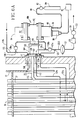
- Nuclear steam generators 1 generally include a primary side 3 and a secondary side 5 which are hydraulically isolated from one another by a tubesheet 7.
- the primary side 3 is bowl-shaped, and is divided into two, hydraulically isolated halves by means of a divider plate 8.
- One of the halves of the primary side 3 includes a water inlet 9 for receiving hot, radioactive water that has been circulated through the core barrel of a nuclear reactor (not shown), while the other half includes a water outlet 13 for discharging this water back to the core barrel.
- This hot, radioactive water circulates through the U-shaped heat exchanger tubes 22 contained within the secondary side 5 of the steam generator 1 from the inlet half of the primary side 3 to the outlet half (see flow arrows).
- the water-receiving half of the primary side 3 is called the inlet channel head 15, while the water-discharging half is called the outlet channel head 17.
- a pair of opposing sludge lance ports 53a, 53b are provided in some models of steam generators to provide access for high pressure hoses that wash away much of the sludge which accumulates over the top of the tubesheets 7 during the operation of the generator 1.
- These opposing sludge lance portions 53a, 53b are typically centrally aligned between the hot and cold legs 24 and 28 of each of the heat exchanger tubes 22. It should be noted that in some steam generators, the sludge lance ports are not oppositely disposed 180 degrees from one another, but are only 90 degrees apart. Moreover, in other steam generators, only one such sludge lance port is provided.
- tube lanes 54 the elongated areas between rows of tubes 22 on the tubesheet 7 are known as tube lanes 54, while the relatively wider, elongated area between the hot and cold legs of the most centrally-disposed heat exchanger tubes 22 is known as the central tube lane 55.
- These tube lines 54 are typically an inch or two wide in steam generators whose tubes 22 are arranged in a square pitch, such as that shown in Figures 3A, 3B and 3C.
- Narrower tube lanes 54 are present in steam generators whose heat exchanger tubes 22 are arranged in a denser, triangular pitch such as shown in Figures 4A and 4B.
- the instant invention is both an apparatus and a method for dislodging and loosening such deposits, sludge and debris and removing them from the secondary side 5 of a steam generator 1.
- the apparatus of the invention generally comprises a pair of pressure pulse generator assemblies 60a, 60b mounted in the two sludge lance ports 53a, 53b, in combination with a recirculation system 114. Because both of these generator assemblies 60a, 60b are identical in all respects, the following description will be confined to generator assembly 60b in order to avoid unnecessary prolixity.
- pulse generator assembly 60b includes an air gun 62 for instantaneously releasing a volume of pressurized gas, and a single port manifold 92 for directing this pressurized gas into a generally tubular nozzle 111 which is aligned along the central tube lane 55 of the steam generator 1.
- the air gun 62 includes a firing cylinder 64 that contains a pulse flattener 65 which together are dimensioned to store about 1442 cubic centimeters of pressurized gas.
- Air gun 62 further includes a trigger cylinder 66 which stores approximately 164 cubic centimeters of pressurized gas, and a plunger assembly 68 having an upper piston 70 and a lower piston 72 interconnected by means of a common connecting rod 74.
- the upper piston 70 can selectively open and close the firing cylinder 64, and the lower piston 72 is reciprocally movable within the trigger cylinder 66 as is indicated in phantom.
- the area of the lower piston 72 that is acted on by pressurized gas in trigger cylinder 66 is greater than the area of the upper piston 70 acted on by pressurized gas in the cylinder 64.
- the connecting rod 74 of the plunger 68 includes a centrally disposed bore 76 for conducting pressurized gas admitted into the trigger cylinder 66 into the firing cylinder 64.
- the pulse flattener 65 also includes a gas conducting bore 77 that is about 12.70 millimeters in diameter.
- pressurized gas of anywhere between approximately 1 and 11 megapascals is admitted into the trigger cylinder 66 by way of gas line 80.
- the pressure that this gas applies to the face of the lower piston 72 of the plunger 68 causes the plunger 68 to assume the position illustrated in Figure 6B, wherein the upper piston 70 sealingly engages the bottom edge of the firing cylinder 64.
- the sealing engagement between the piston 70 and firing cylinder 64 allows the firing cylinder 64 to be charged with pressurized gas that is conducted from the trigger cylinder 66 by way of bore 76 in the connecting rod 74, which in turn flows through the gas-conducting bore 77 in the pulse flattener 65.
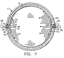
- vent holes 113.9 that are 6.35 millimeters in diameter and 25.4 millimeters apart are provided on the upper side of the tubular body 112 of the nozzle 111 to expedite the refilling of the nozzle 111 with water after each firing of the air gun 62 (as shown in Figure 7).
- the provision of such vent holes 113.9 does not divert any significant portion of the air and water blast from the air gun 62 upwardly.
- the apparatus of the invention further includes a recirculation system 114 that is interconnected with the pressure pulse generator assembly 60b by inlet hose 115, a suction-inlet hose 121a, and a suction hose 121b.
- inlet hose 115 extends through the circular mounting flange 109 of the pressure pulse generator assembly 60b by way of a fitting 117.
- the inlet hose 115 is aligned along the main tube lane 55 above nozzle 111 as is best seen in Figure 7.
- the inlet hose 115 is connected to an inlet conduit 119b that is part of the recirculation system 114.
- Suction-inlet hose 121a and suction hose 121b likewise extend through the mounting flange 109 by way of fittings 123a, 123b.
- Inlet hose 115 is provided with a diverter valve 126a connected thereto by a T-joint 126.1 for diverting incoming water into suction-inlet hose 121a as shown.
- Suction-inlet hose 121a includes an isolation valve 126b as shown just below T-joint 126.2.
- each of the hoses 121a, 121b are connected to the inlet ends of a T-joint 125.
- the outlet end of the T-joint 125 is in turn connected to the inlet of a diaphragm pump 127 by way of conduit 125.5b.
- the use of a diaphragm-type pump 127 is preferred at this point in the recirculation system 114 since the water withdrawn through the hoses 121a, 121b may have large particles of suspended sludge which, while easily handled by a diaphragm-type pump, could damage or even destroy a rotary or positive displacement-type pump.
- the method of the invention is generally implemented by the previously described pressure pulse generator assemblies 60a, 60b in combination with the recirculation system 114.
- the relative condition of the heat exchanger tubes 22 is preferably ascertained by an eddy current or ultrasonic inspection of a type well known in the art. Such an inspection will give the system operators information which they can use to infer the maximum amount of momentary pressures that the tubs 22 of a particular steam generator can safely withstand without any danger of yielding or without undergoing significant metal fatigue.
- heat exchanger tubes 22 in moderately good condition can withstand momentary pressures of up to approximately 131 megapascals without yielding or without incurring significant amounts of metal fatigue.
- relatively old heat exchanger tubes 22 whose walls have been significantly weakened by corrosion and fretting may only be able to withstand only 103 megapascals, while relatively new tubes which are relatively tree of the adverse affects of corrosion or fretting may be able to withstand up to 207 megapascals without any adverse mechanical effects.
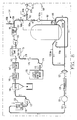
- the recirculation system 114 is connected to each of the pulse generator assemblies 60a, 60b by coupling the inlet hose 115 of each to the flexible inlet conduits 119a and 119b, and the suction-inlet hose 121a and suction hose 121b of each to flexible suction conduits 125.5a, 125.5b via the T-joint 125 of each assembly 60a, 60b.
- the recirculation system 114 is connected via conduit 172 to the supply 170 of deionized water from the utility, as is best seen in Figure 8.
- the flow pump 174 is then actuated in order to fill supply tank 151 approximately one-half full, which will occur when tank 151 receives about 250 gallons of water.
- flow pump 155 is actuated to commence the fill cycle.
- pump 155 generates a flow of purified water of approximately 0.454 cubic meter per minute which is bifurcated to two 0.227 cubic meter per minute flows at T-joint 169 between inlet hose 119a and 119b on opposing sides of the generator 1 in order to fill the secondary side 5 of the steam generator 1.
- valves 165a and 165b are opened and closed so that the entire flow of water from pump 153 enters the generator 1.
- the firing of the air gun 62 of each of the assemblies 60a, 60b commences. If the prior eddy current and ultrasonic testing indicates that the heat exchanger tubes 22 can withstand momentary pressures of approximately 131 megapascals without any deleterious affects, the gas pressure regulators 82 of each of the generator assemblies 60a, 60b is adjusted so that gas of a pressure of about 3 megapascals is initially admitted into the firing cylinders 64 of the air gun 62 of each.
- the gas pressure initially selected for use with the pressure pulse generator assembly 60a, 60b induces momentary pressures that are well below the maximum safe amount of momentary forces that the tubes 22 can actually withstand, for two reasons.
- the pressure of the gas used in the generator assembly 60a, 60b is slowly raised in proportion with the extent to which the secondary side 5 of the steam generator 1 is filled until it is approximately twice as great as the initially chosen value for gas pressure.
- the initial gas pressure used when the water level is just above the nozzles 111 is approximately 3 megapascals
- the final pressure of the gas used in the pressure pulse generator assembly 60a, 60b will be approximately 5.52 to 6.21 megapascals.
- the gas pressure is chosen so that the maximum pressure used will induce momentary forces in the tubes 22 which are at least 30 and preferably 40 percent below the maximum megapascals indicated by the previously mentioned eddy current and ultrasonic inspection to provide a wide margin of safety.
- the gas pressure is chosen so that the maximum pressure used will induce momentary forces in the tubes 22 which are at least 30 and preferably 40 percent below the maximum megapascals indicated by the previously mentioned eddy current and ultrasonic inspection to provide a wide margin of safety.
- the firing of the air gun 62 of both the pulse generators will be synchronous in order to uniformly displace the water throughout the entire cross-section of the secondary side 5 of the generator 1.
- an asynchronous firing of the air guns 62 of the different assemblies may be desirable, such as in a steam generator where the sludge lance ports 53a, 53b are only 90 degrees apart from one another.
- the asynchronous firing of the air guns 62 could possibly help to compensate for the non-opposing arrangement of the pulse generators 60a, 60b in the secondary side 5 imposed by the location of the 90 degree apart sludge lance ports 53a, 53b.
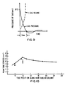
- Figure 9 illustrates how the pressure of the gas within the 1442 cubic centimeter firing cylinder 64 of the air gun 62 diminishes over time
- Figure 10 indicates the peak stress experienced by the column of tubes closest to the nozzle 111.
- the pressure of the gas within the firing cylinder 64 is 6 megapascals, and a 164 cubic centimeter pulse flattener 65 having a gas-conducting bore 13 millimeter in diameter is used, the gas leaves the cylinder 62 over a time period of approximately five milliseconds.
- Figure 10 shows that the peak stress experienced by the column of tubes 22 closest to the tip portion 113 of the nozzle 111 is between 83 and 90 megapascals, which again is safely below the 131 megapascals limit. If no pulse flattener 65 were used, the closest column of heat exchanger tubes 22 in the secondary side 5 to the tip portion 113 of the nozzle 111 would be considerably higher, as the gas would escape from the air gun in a considerably shorter time than 5 milliseconds.
- the filling of the secondary side 5 at a net rate of about 0.265 cubic meter per minute continues until the uppermost support plate 30 is immersed with water.
- about 64 cubic meter of water must be introduced into the secondary side 5 before the water reaches such a level.
- the fill cycle takes about four hours.
- the pressure of the gas introduced into the firing cylinder 64 of each air gun 62 is raised from approximately 3 megapascals to approximately 5.52 to 6.21 megapascals in direct proportion with the water level in the secondary side 5.
- the proportional increase in the pressure of the gas used in the air guns 62 substantially offsets the diminishment in the power of the pulses created thereby caused by the increasing static water pressure around the tip portion 113 of the nozzle 111 of each.
- valves 126a, 126b may be closed and opened, respectively, in order to convert the function of suction-fill hose 121a into a suction hose.
- the flow rate of fill pump 155 is lowered from 0.454 cubic meter per minute to only 0.189 cubic meter per minute, while the withdrawal rate of the diaphragm type suction pump 127 is maintained at 0.189 cubic meter per minute.
- the net result of these adjustments is that water is recirculated through the secondary side 5 of the steam generator 1 at a rate of approximately 0.189 per minute. This circulation rate is maintained for approximately 12-48 hours while the air guns 62 of each of the generator assemblies 60a, 60b are fired at a pressure of 6 megapascals every seven to ten seconds.
- the drain cycle of the method commences. This step is implemented by doubling the flow rate of the diaphragm-type suction pump 127 so that each of the hoses 121a, 121b of each pulse generator 60a, 60b will withdraw approximately 0.085 cubic meter per minute. Since the fill pump 155 continues to fill the secondary side 5 at a total rate of approximately 0.189 cubic meter per minute, the net drain rate is approximately 0.151 cubic meter per minute. As the secondary side 5 has about 64 cubic meters of water in it at the end of the recirculation cycle, the drain cycle takes about seven hours.
- a second steam generator may be filled with the filtered and polished water that flows out of the demineralizer 157 of the recirculation system 114 during the drain cycle of a first steam generator. This may be accomplished by wheeling the portable coupling station 168 over to a second generator where other pulse generator assemblies 60a, 60b have been installed, and coupling the outlet of flowmeter 167b to the inlet conduits 119a, 119b of the second generator. Next, diverter valves 165a and 165b are adjusted so that part of the filtered and polished water leaving the demineralizer 157 is shunted to the inlet conduits 119a, 119b of the second generator.
- the flow rate of the pump 155 is increased to approximately 0.644 cubic meters per minute.
- the valve 165a is adjusted so that the flow rate as indicated by flowmeter 167a remains approximately 0.189 cubic meters per minute.
- the balance of the 0.454 cubic meter per minute flow is shunted through valve 165b to the secondary side 5 of the second steam generator.
Landscapes
- Engineering & Computer Science (AREA)
- Mechanical Engineering (AREA)
- General Engineering & Computer Science (AREA)
- Physics & Mathematics (AREA)
- Chemical & Material Sciences (AREA)
- Combustion & Propulsion (AREA)
- High Energy & Nuclear Physics (AREA)
- Thermal Sciences (AREA)
- Cleaning In General (AREA)
- Heat-Exchange Devices With Radiators And Conduit Assemblies (AREA)
Claims (8)
- Procédé de nettoyage par variation pulsatoire de la pression, destiné à détacher et à éliminer les boues et débris de l'intérieur de la cuve (5) d'un échangeur (1) de chaleur qui contient un ou plusieurs éléments échangeurs de chaleur et qui contient dans cette cuve (5) d'échangeur de chaleur une quantité de liquide suffisante pour immerger une partie de son intérieur qui renferme une certaine quantité de ces boues, débris et des éléments échangeurs de chaleur, ce procédé comprenant le stade de création d'une succession d'impulsions de pression dans le liquide afin de produire des ondes de choc qui exercent des pressions momentanées dans toute la partie immergée de la cuve (5), caractérisé en ce que ce stade de création d'une succession d'impulsions de pression comprend, pour chaque impulsion de pression, une émission en deux temps de gaz sous pression de manière que ces pressions momentanées aient une valeur suffisante pour détacher ces boues et débris, mais insuffisante pour dépasser la limite d'élasticité des éléments de l'échangeur de chaleur.
- Procédé suivant la revendication 1, caractérisé en ce que ces ondes de choc produites dans le liquide créent des pressions momentanées d'une valeur inférieure à environ 241 MPa
- Procédé suivant les revendications 1 ou 2, caractérisé en ce que ces impulsions de pression sont créées par au moins un générateur (60a, 60b) d'impulsions de pression en introduisant un gaz sous pression dans ce liquide, ce gaz étant soumis à une pression comprise entre environ 1 et 11 MPa.
- Procédé suivant la revendication 3, caractérisé en ce que ce générateur (60a, 60b) d'impulsions de pression crée ces impulsions de pression en libérant entre 819 et 1966 cm³ de gaz dans ce liquide.
- Procédé suivant l'une quelconque des revendications 1 à 4, caractérisé en ce que cette impulsion de pression est créée toutes les 1 à 15 secondes environ.
- Procédé suivant l'une quelconque des revendications 1 à 5, caractérisé en ce que deux générateurs (60a, 60b) d'impulsions de pression sont utilisés et sont placés sur les côtés opposés de l'intérieur de la cuve (5), et comprenant en outre le stade de création de ces impulsions par ces générateurs (60a, 60b) à des moments non synchronisés afin de régler l'endroit de la cuve où se heurtent les ondes de choc produites dans le liquide.
- Procédé suivant l'une quelconque des revendications 1 à 5, caractérisé en ce que deux générateurs (60a, 60b) d'impulsions de pression sont utilisés et sont placés sur les côtés opposés de l'intérieur de la cuve (5), et par le stade de création de ces impulsions par ces générateurs (60a, 60b) à des moments synchronisés.
- Appareil de nettoyage par variation pulsatoire de la pression, destiné à détacher les boues et débris de l'intérieur de la cuve (5) d'un échangeur (1) de chaleur, comprenant un moyen (64) pour créer une succession d'impulsions de pression, caractérisé en ce que ce moyen (64) pour créer une succession d'impulsions de pression comprend un cylindre de tir chargeable à l'air sous pression, cet air étant libéré lorsque le cylindre de tir est actionné, et en ce qu'un atténuateur (65) d'impulsions est prévu pour abaisser l'amplitude de ces impulsions de pression créées, cet atténuateur d'impulsions comprenant une paroi dotée d'une ouverture (77) et divisant ce cylindre de tir transversalement au sens d'écoulement du gaz de sorte que, lorsque le cylindre de tir est actionné, le gaz est émis en deux temps.
Priority Applications (2)
| Application Number | Priority Date | Filing Date | Title |
|---|---|---|---|
| DE1989606158 DE68906158T2 (de) | 1989-10-11 | 1989-10-11 | Druckpulsierendes Reinigungsverfahren. |
| EP19890118849 EP0422267B1 (fr) | 1989-10-11 | 1989-10-11 | Méthode de nettoyage par variation pulsatoire de la pression |
Applications Claiming Priority (1)
| Application Number | Priority Date | Filing Date | Title |
|---|---|---|---|
| EP19890118849 EP0422267B1 (fr) | 1989-10-11 | 1989-10-11 | Méthode de nettoyage par variation pulsatoire de la pression |
Publications (2)
| Publication Number | Publication Date |
|---|---|
| EP0422267A1 EP0422267A1 (fr) | 1991-04-17 |
| EP0422267B1 true EP0422267B1 (fr) | 1993-04-21 |
Family
ID=8202010
Family Applications (1)
| Application Number | Title | Priority Date | Filing Date |
|---|---|---|---|
| EP19890118849 Expired - Lifetime EP0422267B1 (fr) | 1989-10-11 | 1989-10-11 | Méthode de nettoyage par variation pulsatoire de la pression |
Country Status (2)
| Country | Link |
|---|---|
| EP (1) | EP0422267B1 (fr) |
| DE (1) | DE68906158T2 (fr) |
Families Citing this family (3)
| Publication number | Priority date | Publication date | Assignee | Title |
|---|---|---|---|---|
| CN102538574A (zh) * | 2010-12-22 | 2012-07-04 | 吴舒克 | 脱水型激波吹灰器 |
| EP3277140B1 (fr) * | 2015-03-30 | 2022-03-23 | Breville Pty Limited | Appareil et procédé perfectionnés de formation de mousse de lait |
| US10502510B2 (en) | 2016-02-09 | 2019-12-10 | Babcock Power Services, Inc. | Cleaning tubesheets of heat exchangers |
Family Cites Families (4)
| Publication number | Priority date | Publication date | Assignee | Title |
|---|---|---|---|---|
| US4655846A (en) * | 1983-04-19 | 1987-04-07 | Anco Engineers, Inc. | Method of pressure pulse cleaning a tube bundle heat exchanger |
| FR2568985A1 (fr) * | 1984-03-14 | 1986-02-14 | Julliard Jacques | Nouveau principe d'elimination des depots accumules au niveau de la plaque tubulaire des generateurs de vapeur de centrales nucleaires a eau pressurisee |
| US4756770A (en) * | 1986-02-11 | 1988-07-12 | Arkansas Power And Light Company | Water slap steam generator cleaning method |
| US4773357A (en) * | 1986-08-29 | 1988-09-27 | Anco Engineers, Inc. | Water cannon apparatus and method for cleaning a tube bundle heat exchanger, boiler, condenser, or the like |
-
1989
- 1989-10-11 DE DE1989606158 patent/DE68906158T2/de not_active Expired - Fee Related
- 1989-10-11 EP EP19890118849 patent/EP0422267B1/fr not_active Expired - Lifetime
Also Published As
| Publication number | Publication date |
|---|---|
| DE68906158T2 (de) | 1993-10-28 |
| DE68906158D1 (de) | 1993-05-27 |
| EP0422267A1 (fr) | 1991-04-17 |
Similar Documents
| Publication | Publication Date | Title |
|---|---|---|
| EP0339289B1 (fr) | Méthode de nettoyage, par variation pulsatoire de la pression | |
| US5092280A (en) | Pressure pulse cleaning apparatus | |
| EP0339288B1 (fr) | Procédé pour le nettoyage par variation pulsatoire de la pression | |
| US5006304A (en) | Pressure pulse cleaning method | |
| US5019329A (en) | System and method for vertically flushing a steam generator during a shock wave cleaning operation | |
| US6572709B1 (en) | Ultrasonic cleaning method | |
| US5764717A (en) | Chemical cleaning method for the removal of scale sludge and other deposits from nuclear steam generators | |
| US4566406A (en) | Sludge removing apparatus for a steam generator | |
| US4273076A (en) | Steam generator sludge lancing apparatus | |
| EP1200789B1 (fr) | Procede de nettoyage par ultrasons | |
| US5841826A (en) | Method of using a chemical solution to dislodge and dislocate scale, sludge and other deposits from nuclear steam generators | |
| US4756770A (en) | Water slap steam generator cleaning method | |
| US4972805A (en) | Method and apparatus for removing foreign matter from heat exchanger tubesheets | |
| CA2369481C (fr) | Dispositif de detartrage pour un generateur de vapeur | |
| EP0458533B1 (fr) | Méthode de nettoyage chimique des générateurs de vapeur par variation pulsatoire de pression | |
| US4848278A (en) | Nuclear steam generator sludge lancing method and apparatus | |
| US5092355A (en) | Pressure pulse method for removing debris from nuclear fuel assemblies | |
| US5002079A (en) | Pressure pulse method and system for removing debris from nuclear fuel assemblies | |
| EP0422267B1 (fr) | Méthode de nettoyage par variation pulsatoire de la pression | |
| JPH0481681B2 (fr) | ||
| EP0422266B1 (fr) | Méthode de nettoyage par variation pulsatoire de la pression | |
| EP0484042B1 (fr) | Méthode pour enlever les boues et les dépôts à l'intérieur d'un réservoir d'échangeur de chaleur | |
| JPS6014096Y2 (ja) | スラツジ除去装置 |
Legal Events
| Date | Code | Title | Description |
|---|---|---|---|
| PUAI | Public reference made under article 153(3) epc to a published international application that has entered the european phase |
Free format text: ORIGINAL CODE: 0009012 |
|
| AK | Designated contracting states |
Kind code of ref document: A1 Designated state(s): DE |
|
| 17P | Request for examination filed |
Effective date: 19910930 |
|
| 17Q | First examination report despatched |
Effective date: 19920727 |
|
| GRAA | (expected) grant |
Free format text: ORIGINAL CODE: 0009210 |
|
| AK | Designated contracting states |
Kind code of ref document: B1 Designated state(s): DE |
|
| REF | Corresponds to: |
Ref document number: 68906158 Country of ref document: DE Date of ref document: 19930527 |
|
| PLBE | No opposition filed within time limit |
Free format text: ORIGINAL CODE: 0009261 |
|
| STAA | Information on the status of an ep patent application or granted ep patent |
Free format text: STATUS: NO OPPOSITION FILED WITHIN TIME LIMIT |
|
| 26N | No opposition filed | ||
| PGFP | Annual fee paid to national office [announced via postgrant information from national office to epo] |
Ref country code: DE Payment date: 19971030 Year of fee payment: 9 |
|
| PG25 | Lapsed in a contracting state [announced via postgrant information from national office to epo] |
Ref country code: DE Free format text: LAPSE BECAUSE OF NON-PAYMENT OF DUE FEES Effective date: 19990803 |