EP0421911A2 - Überführungsvorrichtung zum Überführen des Anlaufbandes einer Papierbahn - Google Patents
Überführungsvorrichtung zum Überführen des Anlaufbandes einer Papierbahn Download PDFInfo
- Publication number
- EP0421911A2 EP0421911A2 EP90630170A EP90630170A EP0421911A2 EP 0421911 A2 EP0421911 A2 EP 0421911A2 EP 90630170 A EP90630170 A EP 90630170A EP 90630170 A EP90630170 A EP 90630170A EP 0421911 A2 EP0421911 A2 EP 0421911A2
- Authority
- EP
- European Patent Office
- Prior art keywords
- dryer
- felt
- roll
- tail
- web
- Prior art date
- Legal status (The legal status is an assumption and is not a legal conclusion. Google has not performed a legal analysis and makes no representation as to the accuracy of the status listed.)
- Granted
Links
Images

Classifications
-
- D—TEXTILES; PAPER
- D21—PAPER-MAKING; PRODUCTION OF CELLULOSE
- D21F—PAPER-MAKING MACHINES; METHODS OF PRODUCING PAPER THEREON
- D21F3/00—Press section of machines for making continuous webs of paper
- D21F3/02—Wet presses
- D21F3/10—Suction rolls, e.g. couch rolls
-
- D—TEXTILES; PAPER
- D21—PAPER-MAKING; PRODUCTION OF CELLULOSE
- D21F—PAPER-MAKING MACHINES; METHODS OF PRODUCING PAPER THEREON
- D21F5/00—Dryer section of machines for making continuous webs of paper
- D21F5/02—Drying on cylinders
- D21F5/04—Drying on cylinders on two or more drying cylinders
-
- D—TEXTILES; PAPER
- D21—PAPER-MAKING; PRODUCTION OF CELLULOSE
- D21F—PAPER-MAKING MACHINES; METHODS OF PRODUCING PAPER THEREON
- D21F5/00—Dryer section of machines for making continuous webs of paper
- D21F5/02—Drying on cylinders
- D21F5/04—Drying on cylinders on two or more drying cylinders
- D21F5/042—Drying on cylinders on two or more drying cylinders in combination with suction or blowing devices
-
- D—TEXTILES; PAPER
- D21—PAPER-MAKING; PRODUCTION OF CELLULOSE
- D21G—CALENDERS; ACCESSORIES FOR PAPER-MAKING MACHINES
- D21G9/00—Other accessories for paper-making machines
- D21G9/0063—Devices for threading a web tail through a paper-making machine
Definitions
- the present invention relates to a transfer apparatus for transferring a tail of a web from a press roll to a dryer of a dryer section. More particularly, the present invention relates to a transfer apparatus in which a dryer felt extends around a lead-in roll disposed adjacent to and spaced relative to a press roll for leading a tail of the web from the press roll to a dryer.
- stock is ejected from a headbox onto a forming wire or between a pair of cooperating forming wires where water is removed from the stock in order to form a paper web.
- the formed web is removed from the forming section by a pick-up roll and is guided through one or more press nips for removing more water from the web.
- the pressed web emerges from the last press nip as a sheet approximately 9 m (30 feet) in width and travelling at (26.6 m/s (60 miles per hour).
- the aforementioned pressed web must then be threaded into and through a dryer section for removing further moisture from the pressed web.
- a narrow tail approximately 6 inches wide, is cut from the pressed web and the entire width of the web is doctored from the press roll to a broke pit.
- the narrow tail is then directed by an air wand around a guide roll and into a converging nip defined between a dryer felt and a baby dryer drum of the dryer section.
- the tail of the web When the tail of the web has been threaded, the tail is widened to the full width of the web so that the full width of the pressed web is threaded into and through the dryer section.
- dryer sections have a dryer felt which extends into close proximity with the press roll such that the dryer felt extends around a lead-in roll disposed adjacent to and spaced relative to the press roll.
- the arrangement is such that an operator merely guides the tail from the press roll to the underside of the dryer felt so that the tail supported beneath the dryer felt is guided into the converging nip between the dryer felt and the baby dryer.
- transfer apparatus which include blow boxes or vacuum boxes disposed on the opposite side of the felt relative to the tail of the web, for drawing the tail into close conformity with the felt.
- a vacuum transfer box of the aforementioned type is disclosed in U.S. Patent No. 3,526,574 to Amend.
- a blow box type arrangement is disclosed in U.S. Patent No. 4,551,203 to Eskelinen.
- the real problem of tail detachment resides in the build-up of a positive air pressure at the in-going, or converging, nip defined between the dryer felt and the baby dryer. Moreover, it has been discovered that in the absence of such an over-pressure there exists no need to draw the tail of the web into close conformity with the dryer felt and that the relatively moist tail of the web will readily adhere to the dryer felt between the lead-in roll and the dryer section.
- the increased air pressure at the converging nip tends to blow the leading edge of the tail away from the converging nip.
- an air pocket is generated between the tail of the web and the felt and such air pocket moves from the leading edge of the tail and progresses back towards the lead-in roll, thereby causing detachment of the tail of the web from the felt.
- the present invention overcomes the aforementioned problem by applying a relatively high vacuum adjacent to the positive air pressure converging nip but on the opposite side of the felt relative to the nip for drawing air from the converging nip through the dryer felt so that the leading edge of the tail of the web may be readily threaded between the dryer felt and the baby dryer.
- Another object of the present invention is the provision of a transfer apparatus in which a dryer felt and the dryer define therebetween a positive air pressure in-going nip.
- a rotatable suction roll is disposed adjacent to and on the opposite side of the felt relative to the in-going nip such that in use of the apparatus, the suction roll generates a flow of air from the positive air pressure in-going nip through the felt.
- the arrangement is such that when the tail of the web is being transferred from the press roll towards the dryer, the tendency for the positive air pressure in the vicinity of the in-going nip to prevent threading of the tail between the felt and the dryer is inhibited.
- Another object of the present invention is the provision of a suction roll which is disposed at a distance within 1 to 2 inches from the dryer so that a positive pressure at the in-going nip is inhibited.
- Another object of the present invention is the provision of a transfer apparatus which includes a suction roll having a rotatable perforate shell and a center shaft which defines a sector-shaped suction zone which is disposed adjacent to and on the opposite side of the felt relative to the in-going nip.
- Another object of the present invention is the provision of a transfer apparatus in which the felt wraps around the perforate shell such that the sector-shaped zone extends towards the dryer a distance within the range 1 to 2 inches from a point at which the felt diverges relative to the suction roll for drawing air through the felt from the in-going nip while maintaining a space between the perforate shell and the dryer to accommodate passage of a wad of paper therethrough in the event of the web wrapping the dryer.
- Another object of the present invention is the provision of a transfer apparatus in which the sector-shaped zone extends away from the dryer a distance within the range 1 to 2 inches from a point at which the felt converges with the perforate shell.
- Another object of the present invention is the provision of a vacuum of at least 4 inches water column (WC) within the sector-shaped suction zone for drawing away the positive air pressure within the converging nip.
- a vacuum of at least 4 inches water column (WC) within the sector-shaped suction zone for drawing away the positive air pressure within the converging nip.
- Another object of the present invention is the provision of a transfer apparatus which includes a deflector shield extending between the lead-in roll and the suction roll for inhibiting the build-up of a positive air pressure in the vicinity of a further in-going nip between the felt and the suction roll and for augmenting the flow of air through the felt from the in-going nip towards the suction roll.
- the present invention relates to a transfer apparatus and method for transferring a tail of a web from a press roll to a dryer of a dryer section.
- the apparatus includes a lead-in roll which is disposed adjacent to and spaced relative to the press roll for leading the web from the press roll towards the dryer.
- a dryer felt extends around the lead-in roll and from the lead-in roll to the dryer such that the web is supported by the felt from the lead-in roll to the dryer.
- the felt and the dryer define therebetween a positive air pressure in-going nip.
- a rotatable suction roll is disposed adjacent to and on the opposite side of the felt relative to the in-going nip such that in use of the apparatus, the suction roll generates a flow of air from the positive air pressure in-going nip through the felt.
- the arrangement is such that when the tail of the web is being transferred from the press roll towards the dryer, the tendency for the positive air pressure in the vicinity of the in-going nip to prevent threading of the tail between the felt and the dryer is inhibited.
- the dryer felt is disposed between the tail of the web and the lead-in roll.
- the suction roll is disposed less than 10.2cm(4 inches) from the dryer and preferable at a distance within the range 2.5 to 5.1 cm (1 to 2 inches) from the dryer.
- the suction roll further includes a rotatable perforate shell and a stationary hollow center shaft which is connected to a source of partial vacuum.
- the center shaft defines a sector-shaped suction zone which is disposed adjacent to and on the opposite side of the felt relative to the in-going nip such that the flow of air flows from the positive air pressure in-going nip through the felt into the suction zone.
- the felt wraps around the perforate shell such that the sector-shaped zone extends towards the dryer a distance that is within the range 2.5 to 5.1cm(1 to 2 inches) from a point at which the felt diverges relative to the suction roll.
- the arrangement is such that air is drawn through the felt from the in-going nip while maintaining a space between the perforate shell and the dryer to accommodate the passage of a wad of paper therethrough in the event of the web wrapping the dryer.
- the sector-shaped zone also extends away from the dryer a distance within the range 2.5 to 5.1 cm(1 to 2 inches) from a point at which the felt converges with the perforate shell.
- the sector-shaped zone maintains a partial vacuum of at least 10.2cm (4inches) WC.
- the transfer apparatus also includes a deflector shield which extends between the lead-in roll and the suction roll.
- the felt is disposed between the tail of the web and the shield, and the shield diverges relative to the felt in a direction from the lead-in roll towards the suction roll for augmenting the flow of air, thereby urging the tail of the web into close conformity with the felt.
- Such deflector shield also inhibits the build-up of a further positive air pressure at the in-going nip defined between the felt and the suction roll.
- the present invention also includes a method of transferring a tail of a web from a press roll to a dryer of a dryer section.
- the method includes the steps of: leading a tail of the web from the press roll around a lead-in roll such that the tail of the web is supported by a felt extending around the lead-in roll and from the lead-in roll to the dryer of the dryer section; and drawing air from a positive pressure in-going nip defined between the felt and the dryer such that the flow of air flows from the in-going nip through the felt towards a rotatable suction roll disposed adjacent to the in-going nip but on the opposite side of the felt relative to the in-going nip such that any tendency for the positive air pressure in the vicinity of the in-going nip to prevent threading of the tail between the felt and the dryer is inhibited.
- FIG. 1 is a side-elevational view of a typical prior art transfer apparatus generally designated 10 for transferring unsupported tail T of a web W from a press roll 12 to a baby dryer 14 of a dryer section generally designated 16.
- the apparatus 10 includes a guide roll 18 for guiding the tail T from the press roll 12 to a converging nip N defined between a dryer felt 20 and the baby dryer 14 of the dryer section 16.
- the threading of the tail T of the web W from the press roll 12 into the converging nip N requires considerable skill on the part of an operator.
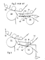
- FIG. 2 is a side-elevational view of another prior art transfer apparatus generally designated 10A for leading a tail TA of a web WA from a press roll 12A to a dryer 14A.
- the apparatus 10A includes a dryer felt 20A which is led into close proximity with the press roll 12A.
- the dryer felt 20A is guided around a lead-in roll 22 disposed adjacent to and spaced relative to the press roll 12A.
- the tail TA to detach from the underside 24 of the felt 20A prior to the leading edge 26 of the tail TA extending between the dryer felt 20A and the dryer 14A.
- FIG. 3 is a side-elevational view of another prior art arrangement as exemplified in U.S. Patent No. 4,551,203 to Eskelinen and shows the provision of a blow box 28.
- a felt 20B is disposed between the box 28 and a tail TB.
- the box draws the tail TB of the web WB into close conformity with the dryer felt 20B.
- Such an arrangement introduces a drawback in that in order to hold the tail of the web against the felt 20B, the required vacuum level is such that the felt 20B is drawn into frictional contact with the edges of the blow box 28, thereby causing scuffing and premature wear of the dryer felt 20B.
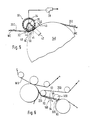
- Figure 4 is a side-elevational view of a transfer apparatus generally designated 10C according to the present invention for transferring a tail TC of a web WC from a press roll 12C to a dryer 14C of a dryer section generally designated 16C.
- the apparatus 10C includes a lead-in roll 22C which is disposed adjacent to and spaced relative to the press roll 12C for leading the tail TC of the web WC from the press roll 12C towards the dryer 14C.
- a dryer felt 20C extends around the lead-in roll 22C and from the lead-in roll 22C to the dryer 14C such that the tail TC of the web WC is supported by the felt 20C from the lead-in roll 22C to the dryer 14C.
- the felt 20C and the dryer 14C define therebetween a positive air pressure in-going nip NC.
- a rotatable suction roll generally designated 30 is disposed adjacent to and on the opposite side of the felt 20C relative to the in-going nip NC such that in use of the apparatus 10C, the suction roll 30 generates a flow of air as indicated by the arrow 32 from the positive air pressure in-going nip NC through the felt 20C such that when the tail TC of the web WC is being transferred from the press roll 12C towards the dryer 14C, the tendency of the positive air pressure in the vicinity of the in-going nip NC to prevent threading of the tail TC between the felt 20C and the dryer 14C is inhibited.
- the dryer felt 20C is disposed between the tail TC of the web WC and the lead-in roll 22C.
- the suction roll 30 is disposed less than 4 inches from the dryer 14C, and in a preferred embodiment of the present invention, as shown in Figure 4, the suction roll 30 is disposed at a distance within the range 1 to 2 inches from the dryer 14C.
- FIG. 5 is an enlarged view of the suction roll generally designated 30 and shows the suction roll 30 as including a rotatable perforate shell 34.
- a stationary hollow shaft 36 is disposed within the shell 34 and is connected to a source of partial vacuum 38.
- the shaft 36 defines a sector-shaped suction zone 40 which is disposed adjacent to and on the opposite side of the felt 20C relative to the in-going nip NC such that the flow of air 32 flows from the positive air pressure in-going nip NC through the felt 20C into the suction zone 40.
- Figure 5 shows the felt 20C as wrapping around the perforate shell 34 such that the sector-shaped zone 40 extends towards the dryer 14Ca distance 42 within the range 1 to 2 inches from a point 44 at which the felt 20C diverges relative to the suction roll 30.
- the arrangement permits drawing air 32 through the felt 20C from the in-going nip NC while maintaining a space indicated by the arrow 46 between the perforate shell 34 and the dryer 14C to accommodate passage of a wad of paper in the event of the web WC breaking and wrapping around the dryer 14C.
- the sector-shaped zone 40 extends away from the dryer 14Ca distance as indicated by the arrow 48 within the range 2.5 to 5.1cm (1 to 2 inches) from a point 50 at which the felt 20C converges with the perforate shell 34.
- the sector-shaped suction zone 40 maintains a partial vacuum of at least 10.2 cm (4 inches) water colunn (WC).
- FIG. 6 is a side-elevational view of a further embodiment of the present invention and shows a transfer apparatus generally designated 10D.
- the apparatus 10D includes a deflector shield 52 which extends between a lead-in roll 22D and a suction roll 30D.
- a felt 20D is disposed between a tail TD of the web WD and the shield 52.
- the shield 52 diverges relative to the felt 20D ina direction as indicated by the arrow 54 from the lead-in roll 22D towards the suction roll 30D.
- Such divergence of the shield 52 generates a flow of air which augments the flow of air as indicated by the arrow 32D which flows from the in-going nip ND towards the suction roll 30D for urging the tail TD of the web WD into close conformity with the felt 20D.
- the generated air flow also inhibits the build-up of a positive air pressure within a further in-going nip 56 defined between the felt 20D and the suction roll 30D.
- the tail TC is supported by and beneath the dryer felt 20C.
- the positive air pressure generated within the in-going nip NC due to the pumping effect between the felt 20C and the dryer 14C is reduced by the suction roll 30 which draws a flow of air 32 from the in-going nip NC through the felt 20C towards the suction roll 30.
- the perforate shell 34 of the suction roll 30 cooperates with the felt 20C, as shown in Figure 5, so that the suction roll 30 is disposed at a distance 46 from the dryer 14C.
- the distance 46 is relatively small so that the suction within the zone 40 effectively reduces the air pressure within the in-going nip NC.
- the distance 46 permits several layers of the web WC to be enwrapped in order to allow time for stopping the rotation of the dryer 14C so that damage to the dryer 14C and the suction roll 30 is prevented.
- the shield 52 diverges relative to the dryer felt 20D so that a partial vacuum is generated between the shield 52 and the dryer felt 20D.
- a partial vacuum augments the flow of air 32D from the positive pressure nip ND and also assists in urging the tail TD into conformity with the dryer felt 20D.
- the shield 52 prevents the build-up of a positive air pressure within a further nip 56 defined between the suction roll 30D and the dryer felt 20D which could otherwise tend to cause detachment of the tail TD from the felt 20D.
- the present invention provides a transfer apparatus which facilitates threading of a tail of a web into a dryer section and inhibits frictional wear of the dryer felt.
Landscapes
- Paper (AREA)
- Advancing Webs (AREA)
Applications Claiming Priority (2)
| Application Number | Priority Date | Filing Date | Title |
|---|---|---|---|
| US07/417,978 US4970805A (en) | 1987-02-13 | 1989-10-05 | Transfer apparatus for transferring a tail of a web |
| US417978 | 1989-10-05 |
Publications (3)
| Publication Number | Publication Date |
|---|---|
| EP0421911A2 true EP0421911A2 (de) | 1991-04-10 |
| EP0421911A3 EP0421911A3 (en) | 1991-07-31 |
| EP0421911B1 EP0421911B1 (de) | 1994-11-30 |
Family
ID=23656141
Family Applications (1)
| Application Number | Title | Priority Date | Filing Date |
|---|---|---|---|
| EP90630170A Expired - Lifetime EP0421911B1 (de) | 1989-10-05 | 1990-10-04 | Überführungsvorrichtung zum Überführen des Anlaufbandes einer Papierbahn |
Country Status (8)
| Country | Link |
|---|---|
| US (1) | US4970805A (de) |
| EP (1) | EP0421911B1 (de) |
| JP (1) | JP2646402B2 (de) |
| KR (1) | KR100205167B1 (de) |
| BR (1) | BR9004968A (de) |
| CA (1) | CA2026841C (de) |
| DE (1) | DE69014540T2 (de) |
| FI (1) | FI106053B (de) |
Cited By (1)
| Publication number | Priority date | Publication date | Assignee | Title |
|---|---|---|---|---|
| WO2005100682A1 (de) * | 2004-04-13 | 2005-10-27 | Voith Patent Gmbh | Maschine zur herstellung einer faserstoffbahn |
Families Citing this family (7)
| Publication number | Priority date | Publication date | Assignee | Title |
|---|---|---|---|---|
| US5404653A (en) | 1987-02-13 | 1995-04-11 | Beloit Technologies, Inc. | Apparatus for drying a web |
| US5507104A (en) | 1987-02-13 | 1996-04-16 | Beloit Technologies, Inc. | Web drying apparatus |
| US6049999A (en) | 1987-02-13 | 2000-04-18 | Beloit Technologies, Inc. | Machine and process for the restrained drying of a paper web |
| DE4015942C1 (de) * | 1990-05-18 | 1991-06-06 | J.M. Voith Gmbh, 7920 Heidenheim, De | |
| FI88812C (fi) * | 1992-03-05 | 1993-07-12 | Valmet Paper Machinery Inc | Anordning vid styrning av banans spetsdragningsband i en pappersmaskin |
| US5546675A (en) * | 1993-11-22 | 1996-08-20 | Beloit Technologies, Inc. | Single tier drying section apparatus |
| AT413709B (de) * | 2004-06-28 | 2006-05-15 | Andritz Ag Maschf | Vorrichtung zum kontinuierlichen trocknen einer faserstoffbahn |
Citations (3)
| Publication number | Priority date | Publication date | Assignee | Title |
|---|---|---|---|---|
| WO1983000514A1 (en) * | 1981-08-13 | 1983-02-17 | Hauser, Ludwig | Group of drying cylinders |
| US4551203A (en) * | 1984-04-02 | 1985-11-05 | Valmet Oy | Method and arrangement for guiding a paper web from the press section to the drying section |
| EP0254666A1 (de) * | 1986-07-18 | 1988-01-27 | Beloit Corporation | Vorrichtung zum Überführen einer Bahn auf eine Trockenpartie |
Family Cites Families (11)
| Publication number | Priority date | Publication date | Assignee | Title |
|---|---|---|---|---|
| DE1901450B1 (de) * | 1969-01-13 | 1970-06-04 | Zum Bruderhaus Gmbh Maschf | Vorrichtung zum UEberfuehren einer aus einer Faserstoffaufschwemmung erzeugten Bahn von dem Maschinensieb einer Siebpartie zu einer in der nachfolgenden Pressenpartie gelegenen Walze |
| DE2323574C3 (de) * | 1973-05-10 | 1976-01-08 | J.M. Voith Gmbh, 7920 Heidenheim | Trockenpartie für Papiermaschinen |
| SE8201904L (sv) * | 1982-03-25 | 1983-09-26 | Svenska Flaektfabriken Ab | Anordning vid cylindertork |
| FI67107C (fi) * | 1983-02-07 | 1985-01-10 | Valmet Oy | Foerfarande och anordning foer ledande av pappersbanan fraon presspartiet till torkpartiet |
| FI68279C (fi) * | 1984-03-22 | 1985-08-12 | Valmet Oy | Foerfarande och anordning foer att hindra pappersbanan att fladdra i torkningspartiet av en pappersmaskin |
| JPS622078A (ja) * | 1985-06-25 | 1987-01-08 | Matsushita Electric Ind Co Ltd | 自動調圧弁 |
| FI71371C (fi) * | 1985-04-17 | 1986-12-19 | Valmet Oy | Foerfarande foer aostadkomma undertryck i en sektor av en valssamt en sugvals |
| US4716660A (en) * | 1986-04-03 | 1988-01-05 | Hercules Incorporated | Unifelt air suction system |
| ATE50303T1 (de) * | 1986-04-08 | 1990-02-15 | Beloit Corp | Blaskasten fuer trockner. |
| DE3706542A1 (de) * | 1987-02-28 | 1988-09-08 | Voith Gmbh J M | Luftleitkasten fuer die trockenpartie einer schnellaufenden papiermaschine |
| US4875976A (en) * | 1988-09-27 | 1989-10-24 | Beloit Corporation | Transfer apparatus from press section to drying section |
-
1989
- 1989-10-05 US US07/417,978 patent/US4970805A/en not_active Expired - Lifetime
-
1990
- 1990-10-03 CA CA002026841A patent/CA2026841C/en not_active Expired - Fee Related
- 1990-10-04 EP EP90630170A patent/EP0421911B1/de not_active Expired - Lifetime
- 1990-10-04 BR BR909004968A patent/BR9004968A/pt not_active IP Right Cessation
- 1990-10-04 DE DE69014540T patent/DE69014540T2/de not_active Expired - Fee Related
- 1990-10-04 FI FI904900A patent/FI106053B/fi active IP Right Grant
- 1990-10-05 JP JP2266531A patent/JP2646402B2/ja not_active Expired - Fee Related
- 1990-10-05 KR KR1019900015966A patent/KR100205167B1/ko not_active IP Right Cessation
Patent Citations (3)
| Publication number | Priority date | Publication date | Assignee | Title |
|---|---|---|---|---|
| WO1983000514A1 (en) * | 1981-08-13 | 1983-02-17 | Hauser, Ludwig | Group of drying cylinders |
| US4551203A (en) * | 1984-04-02 | 1985-11-05 | Valmet Oy | Method and arrangement for guiding a paper web from the press section to the drying section |
| EP0254666A1 (de) * | 1986-07-18 | 1988-01-27 | Beloit Corporation | Vorrichtung zum Überführen einer Bahn auf eine Trockenpartie |
Cited By (1)
| Publication number | Priority date | Publication date | Assignee | Title |
|---|---|---|---|---|
| WO2005100682A1 (de) * | 2004-04-13 | 2005-10-27 | Voith Patent Gmbh | Maschine zur herstellung einer faserstoffbahn |
Also Published As
| Publication number | Publication date |
|---|---|
| EP0421911A3 (en) | 1991-07-31 |
| EP0421911B1 (de) | 1994-11-30 |
| BR9004968A (pt) | 1991-09-10 |
| DE69014540D1 (de) | 1995-01-12 |
| DE69014540T2 (de) | 1995-05-04 |
| FI904900A0 (fi) | 1990-10-04 |
| KR100205167B1 (ko) | 1999-07-01 |
| JP2646402B2 (ja) | 1997-08-27 |
| KR910007785A (ko) | 1991-05-30 |
| FI106053B (fi) | 2000-11-15 |
| CA2026841A1 (en) | 1991-04-06 |
| CA2026841C (en) | 1995-07-04 |
| US4970805A (en) | 1990-11-20 |
| JPH03130489A (ja) | 1991-06-04 |
Similar Documents
| Publication | Publication Date | Title |
|---|---|---|
| EP0254666B1 (de) | Vorrichtung zum Überführen einer Bahn auf eine Trockenpartie | |
| US5087325A (en) | Apparatus for manufacturing a dried web of paper | |
| US4945655A (en) | Apparatus for cutting a tail from a web | |
| US4918836A (en) | Tail cutter apparatus and method | |
| US4874470A (en) | Papermaking press section and transfer arrangement to dryer section | |
| US5232555A (en) | Wet cellulosic web transfer method using air doctor blade | |
| EP0426607A2 (de) | Überführungsvorrichtung | |
| EP0254665A1 (de) | Vorrichtung zum Überführen von Bahnen | |
| US4807371A (en) | Apparatus for maintaining the edges of a web in conformity with a dryer felt | |
| US4970805A (en) | Transfer apparatus for transferring a tail of a web | |
| US4875976A (en) | Transfer apparatus from press section to drying section | |
| EP1122361B1 (de) | Überführen einer Aufführspitze einer Papierbahn | |
| CA2130792A1 (en) | Drying section for web-handling apparatus | |
| EP0865532B1 (de) | Verfahren und anordnung zur verhinderung der wiederbefeuchtung der bahn in einer nasspartie | |
| US5201999A (en) | Twin wire forming apparatus | |
| KR100257276B1 (ko) | 제지기 | |
| US4560438A (en) | Method and apparatus for reducing the energy consumed when drying a paper web | |
| EP0364114A1 (de) | Überführen einer feuchten Zellulosebahn | |
| US6942758B2 (en) | Method and equipment for tail threading in the dryer section of a paper machine or a similar machine | |
| US7377994B2 (en) | Method and device for threading a web in the reeling of a paper or board web | |
| McDonald et al. | A new web transfer system for closing the draw between the last press and the dryer section | |
| US20070180729A1 (en) | Blow box apparatus |
Legal Events
| Date | Code | Title | Description |
|---|---|---|---|
| PUAI | Public reference made under article 153(3) epc to a published international application that has entered the european phase |
Free format text: ORIGINAL CODE: 0009012 |
|
| AK | Designated contracting states |
Kind code of ref document: A2 Designated state(s): DE FR GB IT SE |
|
| PUAL | Search report despatched |
Free format text: ORIGINAL CODE: 0009013 |
|
| AK | Designated contracting states |
Kind code of ref document: A3 Designated state(s): DE FR GB IT SE |
|
| 17P | Request for examination filed |
Effective date: 19910912 |
|
| 17Q | First examination report despatched |
Effective date: 19930611 |
|
| GRAA | (expected) grant |
Free format text: ORIGINAL CODE: 0009210 |
|
| AK | Designated contracting states |
Kind code of ref document: B1 Designated state(s): DE FR GB IT SE |
|
| REF | Corresponds to: |
Ref document number: 69014540 Country of ref document: DE Date of ref document: 19950112 |
|
| EAL | Se: european patent in force in sweden |
Ref document number: 90630170.0 |
|
| ET | Fr: translation filed | ||
| ITF | It: translation for a ep patent filed |
Owner name: UFFICIO BREVETTI RICCARDI & C. |
|
| PLBI | Opposition filed |
Free format text: ORIGINAL CODE: 0009260 |
|
| 26 | Opposition filed |
Opponent name: VOITH SULZER PAPIERMASCHINEN GMBH Effective date: 19950825 |
|
| PLBF | Reply of patent proprietor to notice(s) of opposition |
Free format text: ORIGINAL CODE: EPIDOS OBSO |
|
| PLBF | Reply of patent proprietor to notice(s) of opposition |
Free format text: ORIGINAL CODE: EPIDOS OBSO |
|
| REG | Reference to a national code |
Ref country code: FR Ref legal event code: TP |
|
| REG | Reference to a national code |
Ref country code: GB Ref legal event code: 732E |
|
| RAP2 | Party data changed (patent owner data changed or rights of a patent transferred) |
Owner name: BELOIT TECHNOLOGIES, INC. |
|
| PLBO | Opposition rejected |
Free format text: ORIGINAL CODE: EPIDOS REJO |
|
| APAC | Appeal dossier modified |
Free format text: ORIGINAL CODE: EPIDOS NOAPO |
|
| APAE | Appeal reference modified |
Free format text: ORIGINAL CODE: EPIDOS REFNO |
|
| APAC | Appeal dossier modified |
Free format text: ORIGINAL CODE: EPIDOS NOAPO |
|
| PLBN | Opposition rejected |
Free format text: ORIGINAL CODE: 0009273 |
|
| STAA | Information on the status of an ep patent application or granted ep patent |
Free format text: STATUS: OPPOSITION REJECTED |
|
| 27O | Opposition rejected |
Effective date: 20010726 |
|
| REG | Reference to a national code |
Ref country code: GB Ref legal event code: IF02 |
|
| APAH | Appeal reference modified |
Free format text: ORIGINAL CODE: EPIDOSCREFNO |
|
| PGFP | Annual fee paid to national office [announced via postgrant information from national office to epo] |
Ref country code: DE Payment date: 20071025 Year of fee payment: 18 |
|
| PGFP | Annual fee paid to national office [announced via postgrant information from national office to epo] |
Ref country code: IT Payment date: 20071025 Year of fee payment: 18 |
|
| PGFP | Annual fee paid to national office [announced via postgrant information from national office to epo] |
Ref country code: SE Payment date: 20071012 Year of fee payment: 18 |
|
| PGFP | Annual fee paid to national office [announced via postgrant information from national office to epo] |
Ref country code: FR Payment date: 20071016 Year of fee payment: 18 Ref country code: GB Payment date: 20071023 Year of fee payment: 18 |
|
| EUG | Se: european patent has lapsed | ||
| GBPC | Gb: european patent ceased through non-payment of renewal fee |
Effective date: 20081004 |
|
| REG | Reference to a national code |
Ref country code: FR Ref legal event code: ST Effective date: 20090630 |
|
| PG25 | Lapsed in a contracting state [announced via postgrant information from national office to epo] |
Ref country code: DE Free format text: LAPSE BECAUSE OF NON-PAYMENT OF DUE FEES Effective date: 20090501 Ref country code: IT Free format text: LAPSE BECAUSE OF NON-PAYMENT OF DUE FEES Effective date: 20081004 |
|
| PG25 | Lapsed in a contracting state [announced via postgrant information from national office to epo] |
Ref country code: FR Free format text: LAPSE BECAUSE OF NON-PAYMENT OF DUE FEES Effective date: 20081031 |
|
| PG25 | Lapsed in a contracting state [announced via postgrant information from national office to epo] |
Ref country code: GB Free format text: LAPSE BECAUSE OF NON-PAYMENT OF DUE FEES Effective date: 20081004 |
|
| PG25 | Lapsed in a contracting state [announced via postgrant information from national office to epo] |
Ref country code: SE Free format text: LAPSE BECAUSE OF NON-PAYMENT OF DUE FEES Effective date: 20081005 |