EP0421211B1 - Réacteur pour la mise en oeuvre de procédés biologiques in-vitro, méthode pour la mise en oeuvre de procédés biologiques et utilisation du réacteur et de la méthode - Google Patents
Réacteur pour la mise en oeuvre de procédés biologiques in-vitro, méthode pour la mise en oeuvre de procédés biologiques et utilisation du réacteur et de la méthode Download PDFInfo
- Publication number
- EP0421211B1 EP0421211B1 EP90118243A EP90118243A EP0421211B1 EP 0421211 B1 EP0421211 B1 EP 0421211B1 EP 90118243 A EP90118243 A EP 90118243A EP 90118243 A EP90118243 A EP 90118243A EP 0421211 B1 EP0421211 B1 EP 0421211B1
- Authority
- EP
- European Patent Office
- Prior art keywords
- reaction vessel
- filler
- layers
- reactor
- medium
- Prior art date
- Legal status (The legal status is an assumption and is not a legal conclusion. Google has not performed a legal analysis and makes no representation as to the accuracy of the status listed.)
- Expired - Lifetime
Links
Images

Classifications
-
- C—CHEMISTRY; METALLURGY
- C12—BIOCHEMISTRY; BEER; SPIRITS; WINE; VINEGAR; MICROBIOLOGY; ENZYMOLOGY; MUTATION OR GENETIC ENGINEERING
- C12M—APPARATUS FOR ENZYMOLOGY OR MICROBIOLOGY; APPARATUS FOR CULTURING MICROORGANISMS FOR PRODUCING BIOMASS, FOR GROWING CELLS OR FOR OBTAINING FERMENTATION OR METABOLIC PRODUCTS, i.e. BIOREACTORS OR FERMENTERS
- C12M25/00—Means for supporting, enclosing or fixing the microorganisms, e.g. immunocoatings
- C12M25/02—Membranes; Filters
-
- C—CHEMISTRY; METALLURGY
- C12—BIOCHEMISTRY; BEER; SPIRITS; WINE; VINEGAR; MICROBIOLOGY; ENZYMOLOGY; MUTATION OR GENETIC ENGINEERING
- C12M—APPARATUS FOR ENZYMOLOGY OR MICROBIOLOGY; APPARATUS FOR CULTURING MICROORGANISMS FOR PRODUCING BIOMASS, FOR GROWING CELLS OR FOR OBTAINING FERMENTATION OR METABOLIC PRODUCTS, i.e. BIOREACTORS OR FERMENTERS
- C12M27/00—Means for mixing, agitating or circulating fluids in the vessel
- C12M27/14—Rotation or movement of the cells support, e.g. rotated hollow fibers
Definitions
- the invention relates to a reactor and a method for carrying out biological in vitro processes, in particular cell cultivation, metabolic processes and treatment of flowable media.
- a cultivation vessel or fermenter for the cultivation of human and / or animal cells, a cultivation vessel or fermenter is known from EP-A-205 790, in which a particulate filler coated with growth factors in the form of a bead polymer is arranged in several layers one above the other. The cell culture medium flows through the pearl polymer layers and cell growth with high cell density is obtained.
- the object of the invention is to provide a reactor, a method and a use of reactor and method of the type mentioned, in which it is ensured that the cells that have grown on the filler layers remain adhered, i. H. in particular conditions with low shear force are guaranteed.
- a layer-shaped arrangement of the particulate filler is obtained by the reactor according to the invention, in which the filler layers are fixed in disc-shaped packages at a certain distance from one another along the reaction vessel axis parallel to one another.
- the covering which surrounds the respective filler layers and holds them together, allows diffusion of the flowable medium, which is a nutrient medium or a medium to be treated, e.g. blood to be purified, and possibly also the diffusion of cells.
- the particulate filler can be arranged in layers arranged vertically to the horizontal axis of the vessel, which lie next to one another in the horizontal direction, in the interior of the reactor.
- the reaction vessel is partially filled with the medium in which the biological process is to be carried out, and by rotating the filler layers fixed on the carrier shaft relative to the medium, it is ensured that the filler is retained in the coverings as a respective layer or package . Because of the property of the sheath that allows the medium and / or the cells to diffuse, low-shear conditions are obtained for the course of the reaction, which are particularly advantageous for unimpeded cell growth and for the cells to adhere to the filler particles. At the same time, penetration of the spaces between filler particles with the medium is ensured.
- the cells that have grown in the spaces between the filler particles are constantly supplied with nutrient medium by diffusion.
- reaction vessel with the vertical axis of the vessel, so that the filler particle layers then extend parallel to one another in the horizontal direction and one above the other along the vertical axis of the vessel at a certain distance from each other.
- the envelopes can be filled with the particulate filler under non-sterile conditions. After the filler layers fixed to the carrier shaft have been inserted into the reaction vessel, the inside of the reaction vessel can be autoclaved with the filler layers and then loaded with the cell culture medium.
- the reaction vessel can be designed in the manner of a roller bottle, the carrier shaft with the filler layers attached to it being rotated together with the reaction vessel relative to the medium.
- the carrier shaft is also possible to rotate the carrier shaft together with the filler layers attached to it in relation to the reaction vessel and the medium in the reaction vessel.
- the carrier shaft is then rotatably mounted on the reaction vessel.
- the rotation of the filler layers relative to the medium in the reaction vessel also achieves a stirring effect by means of which a homogeneous distribution of the substances dissolved in the medium, in particular in the cell culture medium, is achieved, such as in a stirred tank.
- Retaining screens preferably made of stainless steel or Teflon, are preferably used as coatings for the respective layers of the filler particles. These holding sieves have a mesh size which allows the cell culture medium or the flowable medium which is to be treated to diffuse through the sieve wall to the filler particles.
- the mesh size of the holding sieves is preferably 40 microns ( ⁇ m) to 100 microns ( ⁇ m).
- a bead polymer whose bead size is> 40 microns ( ⁇ m), up to 300 microns ( ⁇ m) is preferably used as the particulate filler.
- An average diameter size of about 150 to 200 microns ( ⁇ m) is preferred.
- the layer thicknesses of the packet-shaped layers of the bead polymer, which are held together by the holding sieves, are preferably 1000 microns ( ⁇ m) to 2000 microns ( ⁇ m).
- a polymer which can be used is known from EP-A-205 790.
- Mammalian cells in particular human cells, are preferably grown on the bead polymer or filler particles. After removal of the culture medium, the treatment of a flowable medium which is directed past the filler layers covered with the cells in the reaction vessel can then be carried out.
- the reaction vessel is suitable for blood purification.
- the reaction vessel can then be used as an artificial liver.
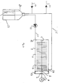
- the exemplary embodiments of a reactor according to the invention shown in the figures each have a cylindrical reaction vessel 1 which is arranged with a horizontal vessel axis (FIGS. 1 and 4) or a vertical vessel axis (FIG. 5).
- a carrier shaft 2 In the axis of the vessel there is a carrier shaft 2, which is rotatably supported on the end faces of the reaction vessel 1 in the embodiments of FIGS. 4 and 5.
- Holding sieves 16 are fastened on the carrier shaft 2 as coverings for a particulate filler 15 with a bioactive surface, in each of which a bead polymer as filler 15, which is coated with growth factors, for example, is arranged in layer form.
- the filler 15 is held in packet-shaped layers 3 on the carrier shaft 2 by the holding sieves 16.
- the holding sieves 16 are shaped in such a way that the packet-shaped layers 3 of the bead polymer 15 have a circular shape which is adapted to the cylindrical interior of the reaction vessel 1.
- the package layers 3 of the bead polymer 15 are arranged at intervals from one another on the carrier shaft 2 next to one another (FIGS. 1 and 4) or one above the other (FIG. 5).
- the carrier shaft 2, with the retaining sieves 16 and the bead polymer attached thereto, is rotatably arranged relative to a medium 5, for example a nutrient solution, located in the reaction vessel 1.
- the distances between the packet layers 3 from one another can be selected within a relatively wide range in the order of 0.1 to 10 mm.
- the carrier shaft 2 can be removed from the reaction vessel 1 together with the holding sieves 16 attached to them.
- a container attachment 17, in which the carrier shaft 5 is mounted can be removed from the remaining part of the reaction vessel 1, so that trouble-free loading of the holding sieves 16 with the bead polymer is made possible.
- the carrier shaft 2 is connected in a rotationally fixed manner to the reaction vessel 1 or the container attachment 17 which can be removed from the rest of the vessel at a fastening point 18.
- the carrier shaft 2 can be released from its shaft bearings 4 after the container cap 17 has been removed (FIG. 4) or the reaction container 1 has been opened.
- the loading of the holding sieves 16 with the filler does not have to be sterile. Sterilization can be carried out after inserting the holding sieves 16 loaded with the bead polymer 15 into the reaction vessel 1 during autoclaving.
- the cell culture medium is then fed in and the cells grow on the bead polymer.
- appropriate biological processes can be used, for example, to produce vaccines, enzymes, hormones, antibodies and other proteins with the aid of the cell cultures obtained.
- treatment of flowable medium for example blood, in particular blood purification, can also be carried out in the reaction vessel 1.
- the cylindrical reaction vessel 1 is in the manner of a roller bottle educated.
- the layers of the particulate filler 15 provided in the holding sieves 16 are arranged vertically next to one another along the horizontally lying carrier shaft 2 in the interior of the reaction vessel 1.
- the carrier shaft 2 is non-rotatably connected to the reaction vessel or to the container attachment 17 at the fastening point 18.
- the medium 5, for example a nutrient solution is filled into the reaction vessel 1.
- the carrier shaft 2 is rotated together with the layers of the particulate filler 15 by rotating the reaction vessel 1 on a roller apparatus 7 about the vessel axis.
- the layers 3 fixed on the carrier shaft 2 with the particulate filler 15, which may have growth factors on its surface, are immersed in the nutrient solution 5 during rotation.
- the remaining part of the interior of the vessel is a gas space 6, in which, after the filler layers have left the medium 5, a gas exchange takes place, for example with O2 or CO2 in the gas space 6.
- the medium 5 can then be exchanged.
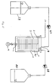
- a cylindrical reaction vessel 1 is also used. However, this reaction vessel 1 is arranged in a stationary manner.
- the carrier shaft 2 with the layers of the bead polymer or filler 15 fixed thereon are rotatably arranged with respect to the reaction vessel 1.
- a drive motor 12 can be provided for the rotary drive of the carrier shaft 2.
- the carrier shaft 2 is rotatably mounted in shaft bearings 4 on the reaction vessel 1.
- the rotary drive can take place via a clutch 8.
- the reaction vessel 1 is equipped with a connection 19 for a medium supply and a connection 20 for a medium discharge.
- the connection 19 for a medium supply in particular a supply of nutrient medium, is connected to a conditioning tank 23 via a line 21, in which a pump 22 is provided.
- the conditioning tank 23 can be fumigated via a fumigation line 24.
- fresh nutrient medium is continuously fed into the interior of the reaction vessel 1 with the aid of the pump 22 and via the line 21 and the connection 19. Used nutrient medium is discharged via the connection 20 and a line 25.
- the inflow of fresh nutrient solution takes place via a line 10 into the conditioning tank 23 and the outflow of the used nutrient solution takes place via a drain line 11.
- the gassing for conditioning the nutrient composition in the conditioning tank takes place via a gassing line 24.
- reaction vessel 1 can also be used in a vertical position for continuous operation.
- the reaction vessel 1 can be used both for cell culture or cell growth and for the production of cell products of the cells obtained in the process. Furthermore, the arrangement shown in FIG. 4 can also be used as an "artificial organ", for example an artificial liver. This can detoxify or convert harmful substances in biological fluids, for example in the blood will.
- the liquid to be detoxified is then kept in a container which is provided in the arrangement instead of the conditioning tank 23 and introduced into the reaction container 1 via the line 21 and the connection 19.
- the detoxified liquid is then passed through the connection 19 and the line 25 and the drain line 11 into a vessel, not shown.
- the cell products are also introduced into a harvesting vessel, not shown, via the connection 20 and the line 25 and the drain line 11.
- the conditioning takes place in the reaction vessel 1.
- a conditioning tank is then no longer required.
- Fresh nutrient solution is kept in readiness in a storage vessel 29 and fed to the reaction vessel 1 by means of a pump 27 via a nutrient solution inflow 9.
- the conditioning of the nutrient composition and the adjustment of pH, pO2, etc. takes place in the reaction vessel 1.
- a fumigation line 26 is used for fumigation, in particular for the supply of O2 and CO2.
- a drain 30 is used to remove used nutrient solution. With the help of a pump 28, this can be brought into a storage container 25.
- the container 25 serves as a so-called harvesting vessel in which the cell products removed from the reaction vessel 1 via the outlet 30 are fed to the vessel 25 by the pump 28.
- the liquid to be detoxified is introduced from the storage container 29 into the reaction vessel 1 for treatment, and the detoxified liquid is then conveyed from the reaction vessel 1 via the drain 30 into the container 25 by the pump 28.
Landscapes
- Health & Medical Sciences (AREA)
- Wood Science & Technology (AREA)
- Life Sciences & Earth Sciences (AREA)
- Engineering & Computer Science (AREA)
- Bioinformatics & Cheminformatics (AREA)
- Organic Chemistry (AREA)
- Chemical & Material Sciences (AREA)
- Zoology (AREA)
- Biomedical Technology (AREA)
- Sustainable Development (AREA)
- Microbiology (AREA)
- Biochemistry (AREA)
- General Engineering & Computer Science (AREA)
- General Health & Medical Sciences (AREA)
- Genetics & Genomics (AREA)
- Biotechnology (AREA)
- Immunology (AREA)
- Apparatus Associated With Microorganisms And Enzymes (AREA)
Claims (16)
- Réacteur pour la réalisation de processus biologiques in vitro, avec un réacteur cylindrique, dans lequel une charge en forme de particules, dont la surface est bioactive, est disposée en couches à la perpendiculaire de l'axe du réacteur, et avec une admission et une évacuation pour un milieu fluide, qui balaye les couches de la charge, caractérisé en ce que- la charge (15) en forme de particules est enrobée dans chacune des couches (3) par une enveloppe (16), perméable pour une diffusion du milieu nutritif (5),- les couches de la charge (15) sont fixées sur un arbre porteur (2), disposé dans l'axe du réacteur, et en ce que- les couches (3) de la charge (15) sont logées avec une possibilité de rotation par rapport au milieu (5), présent dans le réacteur (1).
- Réacteur suivant la revendication 1, caractérisé en ce que l'enveloppe (16) est perméable pour la diffusion de cellules.
- Réacteur suivant l'une des revendications 1 et 2, caractérisé en ce que l'arbre porteur (2) est monté avec une possibilité de rotation sur le réacteur (1).
- Réacteur suivant l'une des revendications 1 et 2, caractérisé en ce que l'arbre porteur (2) est fixé sur le réacteur (1) rotatif, avec lequel il peut tourner.
- Réacteur suivant l'une quelconque des revendications 1 à 4, caractérisé en ce que l'enveloppe (16) est réalisée sous forme de crible de retenue, d'une ouverture de maille de 40 à 100 microns (µm).
- Réacteur suivant l'une quelconque des revendications 1 à 5, caractérisé en ce que la charge (15) en forme de particules est un polymérisat en perles, d'une grosseur de perles de plus de 40 microns (µm).
- Réacteur suivant l'une quelconque des revendications 1 à 6, caractérisé en ce que les couches (3) de la charge (15) présentent respectivement une épaisseur de 1000 à 2000 microns (µm), dans le sens axial du réacteur (1).
- Procédé pour la réalisation d'un processus biologique in vitro, dans lequel est utilisé un réacteur suivant l'une quelconque des revendications 1 à 7, caractérisé en ce que le réacteur (1), avec les couches qu'il contient de charge en forme de particules, dotée d'une surface bioactive, de facteurs de croissance notamment en surface, est utilisé pour une culture cellulaire.
- Procédé suivant la revendication 8, caractérisé en ce que, après la mise en place des couches de la charge en forme de particules, dotée d'une surface bioactive, dans le réacteur, l'intérieur de ce dernier est passé à l'autoclave, puis rempli de milieu de culture cellulaire, et le développement des cellules est assuré.
- Procédé suivant l'une des revendications 8 et 9, caractérisé en ce que la production de produits cellulaires, de produits du métabolisme des cellules notamment, est assurée dans le réacteur, dans lequel se déroule le développement de cellules.
- Procédé suivant l'une quelconque des revendications 8 à 10, caractérisé en ce qu'un milieu fluide à traiter est envoyé sur les couches de la charge, couvertes des cellules, dans le réacteur dans lequel se déroule le développement cellulaire.
- Procédé suivant l'une quelconque des revendications 8 à 11, caractérisé en ce que la charge est couverte de cellules de mammifères.
- Procédé suivant l'une quelconque des revendications 8 à 12, caractérisé en ce que le conditionnement du milieu de culture cellulaire est assuré à l'extérieur du réacteur, le milieu de culture conditionné étant envoyé dans le réacteur.
- Procédé suivant l'une quelconque des revendications 8 à 12, caractérisé en ce que le conditionnement du milieu de culture cellulaire est assuré à l'intérieur du réacteur.
- Procédé suivant l'une quelconque des revendications 8 à 14, caractérisé en ce que la charge en forme de particules est couverte d'hépatocytes, du sang à épurer étant envoyé au travers du réacteur.
- Application d'un réacteur, suivant l'une quelconque des revendications 1 à 7, et d'un procédé, suivant l'une quelconque des revendications 8 à 15, sous forme de foie artificiel.
Priority Applications (1)
| Application Number | Priority Date | Filing Date | Title |
|---|---|---|---|
| AT90118243T ATE100490T1 (de) | 1989-09-29 | 1990-09-22 | Reaktor zur durchfuehrung von biologischen in vitro-prozessen, verfahren zur durchfuehrung eines biologischen in vitro-prozesses und verwendung des reaktors und des verfahrens. |
Applications Claiming Priority (2)
| Application Number | Priority Date | Filing Date | Title |
|---|---|---|---|
| DE3932633A DE3932633C1 (fr) | 1989-09-29 | 1989-09-29 | |
| DE3932633 | 1989-09-29 |
Publications (2)
| Publication Number | Publication Date |
|---|---|
| EP0421211A1 EP0421211A1 (fr) | 1991-04-10 |
| EP0421211B1 true EP0421211B1 (fr) | 1994-01-19 |
Family
ID=6390531
Family Applications (1)
| Application Number | Title | Priority Date | Filing Date |
|---|---|---|---|
| EP90118243A Expired - Lifetime EP0421211B1 (fr) | 1989-09-29 | 1990-09-22 | Réacteur pour la mise en oeuvre de procédés biologiques in-vitro, méthode pour la mise en oeuvre de procédés biologiques et utilisation du réacteur et de la méthode |
Country Status (3)
| Country | Link |
|---|---|
| EP (1) | EP0421211B1 (fr) |
| AT (1) | ATE100490T1 (fr) |
| DE (1) | DE3932633C1 (fr) |
Families Citing this family (4)
| Publication number | Priority date | Publication date | Assignee | Title |
|---|---|---|---|---|
| DE4200446C2 (de) * | 1991-12-14 | 1994-04-07 | Will Prof Dr Minuth | Zellträgeranordnung |
| US5656492A (en) * | 1993-02-12 | 1997-08-12 | Brigham And Women's Hospital, Inc. | Cell induction device |
| WO2001021760A2 (fr) * | 1999-09-24 | 2001-03-29 | Cell Science Therapeutics, Inc. | Fioles rotatives de culture de cellules |
| DE102010005415B4 (de) | 2010-01-22 | 2015-07-16 | Zellwerk Gmbh | Verfahren und Vorrichtung zur dynamischen Expansion und/oder Differenzierung von suspendierten primären Zellen oder Stammzellen humanen und tierischen Ursprungs |
Family Cites Families (5)
| Publication number | Priority date | Publication date | Assignee | Title |
|---|---|---|---|---|
| AU6156780A (en) * | 1979-08-24 | 1981-04-09 | G.D. Searle & Co. | Stack plate culture |
| GB8428085D0 (en) * | 1984-11-07 | 1984-12-12 | Manchester Inst Science Tech | Immobilisation of biological material |
| EP0205790B1 (fr) * | 1985-06-18 | 1992-01-08 | Anawa München Aktiengesellschaft Biologische Laboratorien | Support pour la culture de cellules humaines ou animales dans un fermenteur |
| IT1190289B (it) * | 1986-05-07 | 1988-02-16 | Enea | Procedimento per reazioni biologiche a cellule immobilizzate su supporti e apparecchiatura per realizzarlo |
| DE3634203A1 (de) * | 1986-10-08 | 1988-04-21 | Boehringer Mannheim Gmbh | Bioreaktor zum kultivieren von biologischem material |
-
1989
- 1989-09-29 DE DE3932633A patent/DE3932633C1/de not_active Expired - Fee Related
-
1990
- 1990-09-22 AT AT90118243T patent/ATE100490T1/de not_active IP Right Cessation
- 1990-09-22 EP EP90118243A patent/EP0421211B1/fr not_active Expired - Lifetime
Also Published As
| Publication number | Publication date |
|---|---|
| EP0421211A1 (fr) | 1991-04-10 |
| ATE100490T1 (de) | 1994-02-15 |
| DE3932633C1 (fr) | 1991-04-18 |
Similar Documents
| Publication | Publication Date | Title |
|---|---|---|
| DE19834396C2 (de) | Verfahren zur Oberflächenbeschichtung medizinischer Implantate | |
| EP0052252B1 (fr) | Méthode et appareil pour la culture submergée de cultures de cellules | |
| DE69931800T2 (de) | Strukturierter und poröser silikonkautschuk | |
| DE60026299T2 (de) | Vorrichtung zur züchtung von zellkulturen | |
| DE2934328C2 (de) | Verfahren zur Kultivierung matrixgebundener biologischer Zellsysteme sowie Vorrichtung zur Ausübung des Verfahrens | |
| DE69928997T2 (de) | Zellträgermatrix, Vorrichtung für Zellkulturen und Flüssigkeitsbehandlung | |
| DE3606648C2 (de) | Durchlüftungsvorrichtung für ein Flüssigkeit enthaltendes Zellkulturreaktorsystem | |
| EP1083984B1 (fr) | Technique permettant d'ensemencer des substrats a plusieurs couches avec des cellules biologiques et dispositifs d'ensemencement associes | |
| DE112006000657T5 (de) | Verfahren zur Herstellung biologischen organischen Materials und Kultivierungsgefäss dafür | |
| DE10322054B4 (de) | Vorrichtung und Verfahren zur Kultivierung von Zellen | |
| EP0267408B1 (fr) | Bioréacteur pour culture de matériau biologique | |
| DE2945339C2 (de) | Verfahren und Vorrichtung zum Züchten von biologischen Substanzen | |
| DE2146429A1 (de) | Vorrichtung und Verfahren zur Züchtung von Kulturen | |
| EP1879995B1 (fr) | Procede de fermentation et dispositif associe | |
| EP0495769A2 (fr) | Réacteur pour la mise en oeuvre des réactions biologiques utilisant biocatalyseurs | |
| CH663422A5 (de) | Verfahren und fermenter zur zuechtung von gewebezellen. | |
| EP0421211B1 (fr) | Réacteur pour la mise en oeuvre de procédés biologiques in-vitro, méthode pour la mise en oeuvre de procédés biologiques et utilisation du réacteur et de la méthode | |
| CH651586A5 (de) | Apparat zum zuechten von mikroorganismen auf fluessigen naehrboeden. | |
| EP0365621B1 (fr) | Dispositif de culture submergee de cellules tissulaires | |
| DE4322746A1 (de) | Verfahren und Vorrichtung zur Behandlung von Zellkulturen | |
| EP0224800A2 (fr) | Méthode et appareil pour la culture de cellules | |
| DE102004029709B4 (de) | Vorrichtung und Verfahren zur Zell-Kultivierung in einem Kulturgefäß | |
| DE202005009425U1 (de) | Vorrichtung zur Zell-Kultivierung in einem Kulturgefäß | |
| DE102010005415B4 (de) | Verfahren und Vorrichtung zur dynamischen Expansion und/oder Differenzierung von suspendierten primären Zellen oder Stammzellen humanen und tierischen Ursprungs | |
| CH525959A (de) | Vorrichtung zur Züchtung von Gewebezellen auf der Oberfläche von Trägerkörpern |
Legal Events
| Date | Code | Title | Description |
|---|---|---|---|
| PUAI | Public reference made under article 153(3) epc to a published international application that has entered the european phase |
Free format text: ORIGINAL CODE: 0009012 |
|
| AK | Designated contracting states |
Kind code of ref document: A1 Designated state(s): AT CH FR GB LI |
|
| RAP1 | Party data changed (applicant data changed or rights of an application transferred) |
Owner name: ANAWA MUENCHEN AKTIENGESELLSCHAFT BIOLOGISCHE LABO |
|
| 17P | Request for examination filed |
Effective date: 19910524 |
|
| 17Q | First examination report despatched |
Effective date: 19930428 |
|
| GRAA | (expected) grant |
Free format text: ORIGINAL CODE: 0009210 |
|
| AK | Designated contracting states |
Kind code of ref document: B1 Designated state(s): AT CH FR GB LI |
|
| REF | Corresponds to: |
Ref document number: 100490 Country of ref document: AT Date of ref document: 19940215 Kind code of ref document: T |
|
| ET | Fr: translation filed | ||
| GBT | Gb: translation of ep patent filed (gb section 77(6)(a)/1977) |
Effective date: 19940310 |
|
| PLBE | No opposition filed within time limit |
Free format text: ORIGINAL CODE: 0009261 |
|
| STAA | Information on the status of an ep patent application or granted ep patent |
Free format text: STATUS: NO OPPOSITION FILED WITHIN TIME LIMIT |
|
| 26N | No opposition filed | ||
| PGFP | Annual fee paid to national office [announced via postgrant information from national office to epo] |
Ref country code: GB Payment date: 19990921 Year of fee payment: 10 |
|
| PGFP | Annual fee paid to national office [announced via postgrant information from national office to epo] |
Ref country code: CH Payment date: 19990929 Year of fee payment: 10 |
|
| PGFP | Annual fee paid to national office [announced via postgrant information from national office to epo] |
Ref country code: AT Payment date: 19990930 Year of fee payment: 10 |
|
| PG25 | Lapsed in a contracting state [announced via postgrant information from national office to epo] |
Ref country code: GB Free format text: LAPSE BECAUSE OF NON-PAYMENT OF DUE FEES Effective date: 20000922 Ref country code: AT Free format text: LAPSE BECAUSE OF NON-PAYMENT OF DUE FEES Effective date: 20000922 |
|
| PGFP | Annual fee paid to national office [announced via postgrant information from national office to epo] |
Ref country code: FR Payment date: 20000927 Year of fee payment: 11 |
|
| PG25 | Lapsed in a contracting state [announced via postgrant information from national office to epo] |
Ref country code: LI Free format text: LAPSE BECAUSE OF NON-PAYMENT OF DUE FEES Effective date: 20000930 Ref country code: CH Free format text: LAPSE BECAUSE OF NON-PAYMENT OF DUE FEES Effective date: 20000930 |
|
| GBPC | Gb: european patent ceased through non-payment of renewal fee |
Effective date: 20000922 |
|
| REG | Reference to a national code |
Ref country code: CH Ref legal event code: PL |
|
| PG25 | Lapsed in a contracting state [announced via postgrant information from national office to epo] |
Ref country code: FR Free format text: LAPSE BECAUSE OF NON-PAYMENT OF DUE FEES Effective date: 20020531 |
|
| REG | Reference to a national code |
Ref country code: FR Ref legal event code: ST |