EP0420907B1 - Belt conveyor - Google Patents
Belt conveyor Download PDFInfo
- Publication number
- EP0420907B1 EP0420907B1 EP89907355A EP89907355A EP0420907B1 EP 0420907 B1 EP0420907 B1 EP 0420907B1 EP 89907355 A EP89907355 A EP 89907355A EP 89907355 A EP89907355 A EP 89907355A EP 0420907 B1 EP0420907 B1 EP 0420907B1
- Authority
- EP
- European Patent Office
- Prior art keywords
- belt
- force
- conveyor
- deflecting roller
- edge portion
- Prior art date
- Legal status (The legal status is an assumption and is not a legal conclusion. Google has not performed a legal analysis and makes no representation as to the accuracy of the status listed.)
- Expired - Lifetime
Links
Images


Classifications
-
- B—PERFORMING OPERATIONS; TRANSPORTING
- B65—CONVEYING; PACKING; STORING; HANDLING THIN OR FILAMENTARY MATERIAL
- B65G—TRANSPORT OR STORAGE DEVICES, e.g. CONVEYORS FOR LOADING OR TIPPING, SHOP CONVEYOR SYSTEMS OR PNEUMATIC TUBE CONVEYORS
- B65G15/00—Conveyors having endless load-conveying surfaces, i.e. belts and like continuous members, to which tractive effort is transmitted by means other than endless driving elements of similar configuration
- B65G15/08—Conveyors having endless load-conveying surfaces, i.e. belts and like continuous members, to which tractive effort is transmitted by means other than endless driving elements of similar configuration the load-carrying surface being formed by a concave or tubular belt, e.g. a belt forming a trough
-
- B—PERFORMING OPERATIONS; TRANSPORTING
- B65—CONVEYING; PACKING; STORING; HANDLING THIN OR FILAMENTARY MATERIAL
- B65G—TRANSPORT OR STORAGE DEVICES, e.g. CONVEYORS FOR LOADING OR TIPPING, SHOP CONVEYOR SYSTEMS OR PNEUMATIC TUBE CONVEYORS
- B65G2201/00—Indexing codes relating to handling devices, e.g. conveyors, characterised by the type of product or load being conveyed or handled
- B65G2201/02—Articles
Definitions
- the present invention relates to a belt conveyor comprising an endless belt with two force-absorbing members extending throughout the entire length of the belt and being each connected to a respective edge portion of the belt and projecting from the same side of the belt when this is in the straightened state, and support rollers for supporting the belt along at least a part of the conveying path.
- Belt conveyors of this type are previously known from, for example, US-A-3,164,238 and SE-C-7809688-0. They are advantageous in that they afford a closed conveyance of goods, require but little space, and can be opened for turning about and emptying over a deflecting roller.
- the belt is carried via the two force-absorbing members which have but low extensibility in the longitudinal direction.
- the force-absorbing members are conducted immediately adjacent one another. If the force-absorbing members are conducted in side-by-side relation through a horizontal curve, they will be forced to follow paths of different lengths, which is undesirable. If, instead the two force-absorbing members are conducted above one another through a horizontal curve, they will, it is true, have the same length of travel, but adjacent belt parts will be subjected to heavy wear, bending or elongation, whereby these parts are rapidly worn out.
- each force-absorbing member is connected to its belt edge portion via a narrow hinge portion enabling said member to turn through about ⁇ 90° relative to said belt edge portion for guiding the belt about a deflecting roller whose axis is substantially perpendicular to the plane of the adjacent conveyor belt part, the two force-absorbing members being turned in the same direction relative to the respective belt edge portion and located at substantially the same distance from the axis of the deflecting roller.
- the bag-shaped part of the belt between the force-absorbing members will then with its centre follow a path which is spaced from the axis of the deflecting roller by the same distance as the force-absorbing members, whereby elongation of the belt is substantially avoided so that the belt can be conducted about a deflecting roller at a very small radius at an optional angle of wrap of up to 180°. Because of the hinge portions according to the invention, substantially the entire belt, including the force-absorbing members, can move at one and the same radial distance about the deflecting roller.
- the deflecting roller preferably is a V-belt pulley. It may have a single V-belt groove, in which case the two force-absorbing members together form a V-belt fitting into one V-belt groove, or two adjacent V-belt grooves, in which case each force-absorbing member forms a V-belt fitting into the respective groove.
- these members are suitably polygonal in cross-section, with an acute angle between the two sides of the polygon that connect to the hinge portion.
- each force-absorbing member has a V-belt shape where the broad side of the V-belt is an extension of the belt in its straightened state.
- the reinforcement may be a rope, such as a wire, which is circular in cross-section.
- the reinforcement may be substantially planar in cross-section and disposed in a plane substantially perpendicular to the belt in the straightened state thereof.
- Fig. 1 is a cross-sectional view of an endless conveyor belt that can be used with the belt conveyor according to the invention.
- Fig. 2 is a cross-sectional view of the belt in Fig. 1 and shows the belt in its closed state supported by support rollers.
- Fig. 3 is a cross-sectional view of the belt in Fig. 1 and shows how the belt according to the invention is conducted in a horizontal curve over a deflecting roller.
- Fig. 4 is a schematic perspective view showing the deflecting roller according to Fig. 3 and adjacent parts of the belt conveyor according to the invention.
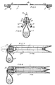
- Figs. 5-7 correspond to Figs. 1-3, but show a more preferred embodiment of the belt and the deflecting roller.
- Fig. 8 corresponds to Fig. 7, but shows still another variant of the belt and the deflecting roller.
- Fig. 9 illustrates on a larger scale three different embodiments of the hinge portion according to the invention.
- a belt conveyor 1 as shown in Figs. 1-4 consists mainly of a flexible and extensible material, such as rubber.
- Each edge portion of the belt is connected to a force-absorbing member 2, 3 extending throughout the entire length of the belt and capable of absorbing both tensile forces and load forces.
- the members 2, 3 are connected to the respective belt edge portion via a narrow hinge portion 4, 5 enabling the member 2, 3 to be turned through approximately ⁇ 90° relative to the belt edge portion, as shown by dash lines to the right in Fig. 1.
- the intermediate portion 6 of the belt 1, between the hinge portions 4, 5, may preferably have a fabric insert with the fibres of the fabric being directed for example +45° relative to the longitudinal direction of the belt 1.
- the fabric insert does not absorb tensile forces, but merely serves to distribute the load forces.
- the force-absorbing members 2, 3 are also reinforced, for example with a rope 7, 8 in the form of a steel wire.
- the belt 1 may be in the state shown in Fig. 1 during its movement about, for example, a turning roller in the form of a turning drum with peripheral grooves for receiving the force-absorbing members 2, 3.
- the belt is preferably closed in the manner shown in Fig. 2.
- the belt 1 is supported via the force-absorbing members 2, 3 by two support rollers 9, 10 which in turn are rotatably mounted in a frame (not shown) about axes of rotation 11, 12 shown by dash lines.
- the angles A shown in Fig. 2 are acute angles.
- the force-absorbing members 2, 3 may be polygonal in cross-section and then have an acute angle between the two sides of the polygon which connect to the respective hinge portion 4, 5.
- the belt 1, as shown in Fig. 3 can be conducted in closed shape through a horizontal curve about a deflecting roller 13 having a vertical axis of rotation 14.
- the deflecting roller 13 has a V-shaped groove profile for engagement with the force-absorbing members 2, 3 which are turned through 90° in the same direction relative to the respective belt edge portion and, furthermore, assume essentially the same mutual position as in Fig. 2.
- the members 2, 3 are turned substantially in relation to a centre line through the bag-shaped part of the belt 1.
- the force-absorbing members are at substantially the same distance from the axis of rotation of the deflecting roller 13, and this applies also to the reinforcing ropes 7, 8 of the members 2, 3, and to the intermediate portion of the belt 1 which lies between the hinge portions 4, 5 and therefore is not subjected to any substantial elongation.
- the belt 1 may also be conducted through a horizontal curve in the opposite direction, in that the force-absorbing members 2, 3 are turned substantially through 90° from the position shown in Fig. 2 into the opposite direction relative to the position shown by full lines in Fig. 3. The 90° turn provides for complete symmetry regarding the members 2, 3 relative to the deflecting roller 13 and the axis of rotation 14 thereof.
- Fig. 4 The transition from the support rollers 9, 10 to the deflecting roller 13 is shown schematically in Fig. 4. Additional rollers (not shown) may be required for guiding the force-absorbing members 2, 3 into engagement with the deflecting roller 13, or vice versa.
- the deflecting roller 13 in the above description is said to have a vertical axis of rotation to facilitate conducting the belt through a horizontal curve
- its axis of rotation 14 may, of course, also have a different spatial orientation as long as the axis 14 is substantially perpendicular to the plane of the adjacent conveyor belt part, as shown in Fig. 4.
- Figs. 5-7 illustrate another preferred embodiment of a conveyor belt 1' and a deflecting roller 13' according to the invention.
- the belt 1' is identical with the one shown in Figs. 1-4, excepting the cross-sectional shape of its force-absorbing members 2', 3'.
- the force-absorbing members 2', 3' also have a different reinforcement 7', 8' than the members 2, 3 in Figs. 1-4, but this difference is immaterial to the function of the embodiment according to Figs. 5-7.
- the force-absorbing members 2', 3' In their position immediately adjacent one another (as shown in Figs. 6 and 7), in which they support the belt 1', the force-absorbing members 2', 3' together form a V-rope having a top angle B.
- the deflecting roller 13' is formed as a V-belt pulley, the groove angle of which makes the angle B. Furthermore, the groove has, in conventional manner, a depth such that the members 2', 3' do not come in contact with the bottom of the groove.
- the reinforcement 7', 8' of the members 2', 3' is a planar reinforcement. More particularely, the plane of the reinforcement is substantially perpendicular to the plane of the belt 1' in the straightened state of the belt. This orientation of the reinforcement is advantageous both along substantially straight reaches of the conveying path where the belt is carried in the manner shown in Fig. 6, because the reinforcement 7', 8' is here equally loaded in every part, and about the V-belt pulley 13' because here all parts of the reinforcement 7', 8' are at the same distance from the axis of rotation 14.
- each force-absorbing member may be in the form of a V-rope 2'', 3'' as shown in Fig. 8 where the deflecting roller 13'' having the axis of rotation 14 is formed with double grooves each receiving one of the members 2'', 3''.
- Fig. 9 illustrates three different hinge connections between the intermediate portion 6 of the conveyor belt 1 and, for example, the force-absorbing member 3' via the hinge portion 5.
- the hinge portion 5 is a separate member fixedly connected, for example by vulcanisation, with both the member 3' and the side edge of the intermediate portion 6 of the belt 1. In this manner, each member 3', 5 and 6 can be conveniently given the desired characteristics.
- the hinge portion 5 may be formed as an integrated part of the belt 1, for example by making it in one piece with and at the same time as the intermediate portion 6, as shown in Fig. 9b and c.
- the hinge portion 5 can be given its flexibility by making it from some pliable material, by reducing its thickness and/or by omitting the reinforcement, although this is not especially shown in Figs. 9b and c.
- the member 3' is manufactured separately, and the members 8', 5 and 6 in one piece. Finally, the member 3' is joined to the member 8'.
- Fig. 9c mainly corresponds to the one shown in Fig. 9b, excepting the location of the reinforcement 8'.
- the hinge portion 5 besides its flexibility, preferably also has a substantial extensibility in the longitudinal and/or transverse direction. Of the utmost importance is that the hinge portion 5 is a distinct hinge point about which the belt will flex naturally. In other words, the hinge portion must have an essentially higher flexibility than the remaining parts of the belt 1.
Landscapes
- Engineering & Computer Science (AREA)
- Mechanical Engineering (AREA)
- Belt Conveyors (AREA)
- Structure Of Belt Conveyors (AREA)
Priority Applications (1)
| Application Number | Priority Date | Filing Date | Title |
|---|---|---|---|
| AT89907355T ATE97089T1 (de) | 1988-06-23 | 1989-06-20 | Foerderband. |
Applications Claiming Priority (2)
| Application Number | Priority Date | Filing Date | Title |
|---|---|---|---|
| SE8802367A SE461212B (sv) | 1988-06-23 | 1988-06-23 | Brandtransportoer |
| SE8802367 | 1988-06-23 |
Publications (2)
| Publication Number | Publication Date |
|---|---|
| EP0420907A1 EP0420907A1 (en) | 1991-04-10 |
| EP0420907B1 true EP0420907B1 (en) | 1993-11-10 |
Family
ID=20372718
Family Applications (1)
| Application Number | Title | Priority Date | Filing Date |
|---|---|---|---|
| EP89907355A Expired - Lifetime EP0420907B1 (en) | 1988-06-23 | 1989-06-20 | Belt conveyor |
Country Status (6)
| Country | Link |
|---|---|
| US (1) | US5083658A (sv) |
| EP (1) | EP0420907B1 (sv) |
| AU (1) | AU3848789A (sv) |
| DE (1) | DE68910688T2 (sv) |
| SE (1) | SE461212B (sv) |
| WO (1) | WO1989012593A1 (sv) |
Families Citing this family (10)
| Publication number | Priority date | Publication date | Assignee | Title |
|---|---|---|---|---|
| DE4213645A1 (de) * | 1992-04-25 | 1993-10-28 | Foerderanlagen Und Maschinenba | Schlaufengurt-Fördersystem |
| SE504756C2 (sv) * | 1994-06-23 | 1997-04-21 | Sicon Roulunds Ab | Vändanordning för transportband |
| DE19544026A1 (de) * | 1995-11-25 | 1997-05-28 | Habasit Gmbh | Schlauchfördergurt |
| FR2770501B1 (fr) | 1997-10-31 | 1999-12-31 | Aries Packaging | Convoyeur accumulateur modulaire multivoies a courroies d'entrainement partiellement escamotables sous charge |
| AUPQ401299A0 (en) | 1999-11-12 | 1999-12-09 | Pietsch, Michael | Continous haulage system |
| US8141698B2 (en) * | 2006-04-07 | 2012-03-27 | Michael Pietsch | Coupling arrangement and system for continuous haulage conveyor |
| US9381454B2 (en) | 2009-05-19 | 2016-07-05 | Z-Filter (Pty) Ltd | Materials handling and treatment |
| DE102013111190A1 (de) | 2013-10-10 | 2015-04-16 | Contitech Transportbandsysteme Gmbh | Fördergurt mit hoher Flexibilität und gleichzeitiger hoher Flammwidrigkeit |
| CN106081533A (zh) * | 2016-08-09 | 2016-11-09 | 林妮子 | 一种管道运输的传送带输送装置 |
| CN106743145A (zh) * | 2017-03-07 | 2017-05-31 | 哈尔滨纳诺机械设备有限公司 | 一种封闭式输送机 |
Family Cites Families (5)
| Publication number | Priority date | Publication date | Assignee | Title |
|---|---|---|---|---|
| US3164238A (en) * | 1961-06-16 | 1965-01-05 | Mccullagh Morris Behan | Continuous conveyors |
| SE428460B (sv) * | 1980-06-10 | 1983-07-04 | Beltline Ab C O Linden Alimak | Transportanleggning for transport av foretredesvis grovstyckigt gods |
| JPS60144211A (ja) * | 1983-12-29 | 1985-07-30 | Tokai Rubber Ind Ltd | 円筒形コンベアベルト |
| DE3424825A1 (de) * | 1984-07-06 | 1986-02-06 | Gerd Prof. Dr.-Ing. 6101 Roßdorf Herziger | Verfahren und einrichtung zum bearbeiten von werkstuecken mittels laserstrahl |
| SE456736B (sv) * | 1985-12-09 | 1988-10-31 | Scaniainventor Ab | Anordning vid bandtransportoerer |
-
1988
- 1988-06-23 SE SE8802367A patent/SE461212B/sv not_active IP Right Cessation
-
1989
- 1989-06-20 US US07/659,390 patent/US5083658A/en not_active Expired - Fee Related
- 1989-06-20 WO PCT/SE1989/000354 patent/WO1989012593A1/en active IP Right Grant
- 1989-06-20 DE DE68910688T patent/DE68910688T2/de not_active Expired - Fee Related
- 1989-06-20 EP EP89907355A patent/EP0420907B1/en not_active Expired - Lifetime
- 1989-06-20 AU AU38487/89A patent/AU3848789A/en not_active Abandoned
Also Published As
| Publication number | Publication date |
|---|---|
| SE8802367D0 (sv) | 1988-06-23 |
| AU3848789A (en) | 1990-01-12 |
| DE68910688D1 (de) | 1993-12-16 |
| DE68910688T2 (de) | 1994-06-09 |
| SE461212B (sv) | 1990-01-22 |
| SE8802367L (sv) | 1989-12-24 |
| EP0420907A1 (en) | 1991-04-10 |
| US5083658A (en) | 1992-01-28 |
| WO1989012593A1 (en) | 1989-12-28 |
Similar Documents
| Publication | Publication Date | Title |
|---|---|---|
| US4024949A (en) | Traverse bendable endless belt conveyor | |
| US3967720A (en) | Belt conveyors | |
| EP0420907B1 (en) | Belt conveyor | |
| US4358010A (en) | Conveyor | |
| JPS62500582A (ja) | バルク材料を取り扱うためのコンベヤベルト | |
| US4645070A (en) | Dual bend conveyor | |
| EP1054825B1 (en) | Conveyor device | |
| EP0878418B1 (en) | Side-flexing conveyor construction | |
| US4711346A (en) | Plastic conveyor belt with extension-resistant reinforcement and drive gearing | |
| EP0286637B1 (en) | Arrangement in a belt conveyor | |
| US4766995A (en) | Pusher-type conveyor chain | |
| US3666085A (en) | Mechanical belting | |
| US5305869A (en) | Chain link conveyor | |
| US5129506A (en) | Space conveyor for newspaper, books and magazines | |
| US6415905B1 (en) | Transport device | |
| AU2002315371B2 (en) | Link having a twisted side guard | |
| US3545598A (en) | Laterally flexible belt conveyor | |
| US4227609A (en) | Bucket conveyor | |
| US7159709B2 (en) | Conveyor belt | |
| US3038590A (en) | Fluted tail pulley | |
| US4623061A (en) | Belt conveyor arrangement | |
| US4809845A (en) | Hose belt conveyer system | |
| US4129209A (en) | Bucket elevator | |
| CA2008718C (en) | Belt conveyor | |
| US20020175056A1 (en) | Side-flexing conveyor belt |
Legal Events
| Date | Code | Title | Description |
|---|---|---|---|
| PUAI | Public reference made under article 153(3) epc to a published international application that has entered the european phase |
Free format text: ORIGINAL CODE: 0009012 |
|
| 17P | Request for examination filed |
Effective date: 19901218 |
|
| AK | Designated contracting states |
Kind code of ref document: A1 Designated state(s): AT BE CH DE FR GB IT LI LU NL |
|
| 17Q | First examination report despatched |
Effective date: 19930127 |
|
| GRAA | (expected) grant |
Free format text: ORIGINAL CODE: 0009210 |
|
| ITF | It: translation for a ep patent filed |
Owner name: ING. A. GIAMBROCONO & C |
|
| AK | Designated contracting states |
Kind code of ref document: B1 Designated state(s): AT BE CH DE FR GB IT LI LU NL |
|
| REF | Corresponds to: |
Ref document number: 97089 Country of ref document: AT Date of ref document: 19931115 Kind code of ref document: T |
|
| REF | Corresponds to: |
Ref document number: 68910688 Country of ref document: DE Date of ref document: 19931216 |
|
| ET | Fr: translation filed | ||
| PG25 | Lapsed in a contracting state [announced via postgrant information from national office to epo] |
Ref country code: LU Free format text: LAPSE BECAUSE OF NON-PAYMENT OF DUE FEES Effective date: 19940630 |
|
| PLBI | Opposition filed |
Free format text: ORIGINAL CODE: 0009260 |
|
| 26 | Opposition filed |
Opponent name: BERNHARD BEUMER MASCHINENFABRIK KG/ CONTINENTAL A Effective date: 19940805 |
|
| NLR1 | Nl: opposition has been filed with the epo |
Opponent name: BERNHARD BEUMER MASCHINENFABRIK KG/ CONTINENTAL AG |
|
| PLBM | Termination of opposition procedure: date of legal effect published |
Free format text: ORIGINAL CODE: 0009276 |
|
| STAA | Information on the status of an ep patent application or granted ep patent |
Free format text: STATUS: OPPOSITION PROCEDURE CLOSED |
|
| 27C | Opposition proceedings terminated |
Effective date: 19941229 |
|
| REG | Reference to a national code |
Ref country code: GB Ref legal event code: IF02 |
|
| PGFP | Annual fee paid to national office [announced via postgrant information from national office to epo] |
Ref country code: GB Payment date: 20020524 Year of fee payment: 14 |
|
| PGFP | Annual fee paid to national office [announced via postgrant information from national office to epo] |
Ref country code: DE Payment date: 20020605 Year of fee payment: 14 Ref country code: CH Payment date: 20020605 Year of fee payment: 14 |
|
| PGFP | Annual fee paid to national office [announced via postgrant information from national office to epo] |
Ref country code: AT Payment date: 20020606 Year of fee payment: 14 |
|
| PGFP | Annual fee paid to national office [announced via postgrant information from national office to epo] |
Ref country code: FR Payment date: 20020611 Year of fee payment: 14 |
|
| PGFP | Annual fee paid to national office [announced via postgrant information from national office to epo] |
Ref country code: NL Payment date: 20020627 Year of fee payment: 14 Ref country code: BE Payment date: 20020627 Year of fee payment: 14 |
|
| PG25 | Lapsed in a contracting state [announced via postgrant information from national office to epo] |
Ref country code: GB Free format text: LAPSE BECAUSE OF NON-PAYMENT OF DUE FEES Effective date: 20030620 Ref country code: AT Free format text: LAPSE BECAUSE OF NON-PAYMENT OF DUE FEES Effective date: 20030620 |
|
| PG25 | Lapsed in a contracting state [announced via postgrant information from national office to epo] |
Ref country code: LI Free format text: LAPSE BECAUSE OF NON-PAYMENT OF DUE FEES Effective date: 20030630 Ref country code: CH Free format text: LAPSE BECAUSE OF NON-PAYMENT OF DUE FEES Effective date: 20030630 Ref country code: BE Free format text: LAPSE BECAUSE OF NON-PAYMENT OF DUE FEES Effective date: 20030630 |
|
| BERE | Be: lapsed |
Owner name: SCANIAINVENTOR CONVEYOR *SICON A.B. Effective date: 20030630 |
|
| PG25 | Lapsed in a contracting state [announced via postgrant information from national office to epo] |
Ref country code: NL Free format text: LAPSE BECAUSE OF NON-PAYMENT OF DUE FEES Effective date: 20040101 Ref country code: DE Free format text: LAPSE BECAUSE OF NON-PAYMENT OF DUE FEES Effective date: 20040101 |
|
| GBPC | Gb: european patent ceased through non-payment of renewal fee |
Effective date: 20030620 |
|
| REG | Reference to a national code |
Ref country code: CH Ref legal event code: PL |
|
| PG25 | Lapsed in a contracting state [announced via postgrant information from national office to epo] |
Ref country code: FR Free format text: LAPSE BECAUSE OF NON-PAYMENT OF DUE FEES Effective date: 20040227 |
|
| NLV4 | Nl: lapsed or anulled due to non-payment of the annual fee |
Effective date: 20040101 |
|
| REG | Reference to a national code |
Ref country code: FR Ref legal event code: ST |
|
| PG25 | Lapsed in a contracting state [announced via postgrant information from national office to epo] |
Ref country code: IT Free format text: LAPSE BECAUSE OF NON-PAYMENT OF DUE FEES Effective date: 20050620 |