EP0878418B1 - Side-flexing conveyor construction - Google Patents
Side-flexing conveyor construction Download PDFInfo
- Publication number
- EP0878418B1 EP0878418B1 EP98108794A EP98108794A EP0878418B1 EP 0878418 B1 EP0878418 B1 EP 0878418B1 EP 98108794 A EP98108794 A EP 98108794A EP 98108794 A EP98108794 A EP 98108794A EP 0878418 B1 EP0878418 B1 EP 0878418B1
- Authority
- EP
- European Patent Office
- Prior art keywords
- eyes
- conveyor
- intended
- laterally spaced
- accordance
- Prior art date
- Legal status (The legal status is an assumption and is not a legal conclusion. Google has not performed a legal analysis and makes no representation as to the accuracy of the status listed.)
- Expired - Lifetime
Links
Images


Classifications
-
- B—PERFORMING OPERATIONS; TRANSPORTING
- B65—CONVEYING; PACKING; STORING; HANDLING THIN OR FILAMENTARY MATERIAL
- B65G—TRANSPORT OR STORAGE DEVICES, e.g. CONVEYORS FOR LOADING OR TIPPING, SHOP CONVEYOR SYSTEMS OR PNEUMATIC TUBE CONVEYORS
- B65G17/00—Conveyors having an endless traction element, e.g. a chain, transmitting movement to a continuous or substantially-continuous load-carrying surface or to a series of individual load-carriers; Endless-chain conveyors in which the chains form the load-carrying surface
- B65G17/06—Conveyors having an endless traction element, e.g. a chain, transmitting movement to a continuous or substantially-continuous load-carrying surface or to a series of individual load-carriers; Endless-chain conveyors in which the chains form the load-carrying surface having a load-carrying surface formed by a series of interconnected, e.g. longitudinal, links, plates, or platforms
- B65G17/08—Conveyors having an endless traction element, e.g. a chain, transmitting movement to a continuous or substantially-continuous load-carrying surface or to a series of individual load-carriers; Endless-chain conveyors in which the chains form the load-carrying surface having a load-carrying surface formed by a series of interconnected, e.g. longitudinal, links, plates, or platforms the surface being formed by the traction element
- B65G17/086—Conveyors having an endless traction element, e.g. a chain, transmitting movement to a continuous or substantially-continuous load-carrying surface or to a series of individual load-carriers; Endless-chain conveyors in which the chains form the load-carrying surface having a load-carrying surface formed by a series of interconnected, e.g. longitudinal, links, plates, or platforms the surface being formed by the traction element specially adapted to follow a curved path
-
- B—PERFORMING OPERATIONS; TRANSPORTING
- B65—CONVEYING; PACKING; STORING; HANDLING THIN OR FILAMENTARY MATERIAL
- B65G—TRANSPORT OR STORAGE DEVICES, e.g. CONVEYORS FOR LOADING OR TIPPING, SHOP CONVEYOR SYSTEMS OR PNEUMATIC TUBE CONVEYORS
- B65G2201/00—Indexing codes relating to handling devices, e.g. conveyors, characterised by the type of product or load being conveyed or handled
- B65G2201/02—Articles
Definitions
- the invention relates generally to modular conveyors (which term includes belts and chains) and, more particularly but not exclusively to such conveyors which include side-flexing capability, i.e. the ability to turn left or right in the plane of conveyor movement.
- Previous designs for side-flexing modular belting or chain involved simply forming slotted holes where the pin joins the links to allow side-flexure of the links in the direction of travel. These previous designs have several limitations.
- the first limitation is that, because of the slotted holes, the belt or chain can expand and compress. This elasticity requires tension to always be placed on the modular belting for proper running i.e., the belting was always preloaded for proper functionality.
- the second limitation is inherent in the prior designs and results in carrying of the entire load, when the chain is side-flexing, at the sides of the chain.
- the outer portion of the pin carries the entire load in side-flexing because the pin only contacts the links at that point.
- a conveyor having in combination the features according to the preamble of claim 1 is known for example from US 5,224,583.
- the present invention provides a conveyor for travel along an intended direction on a given path and having laterally spaced and opposed sides, said conveyor comprising a plurality of chain pins which pivotally and serially interconnect a plurality of link modules, each of the link modules including a first plurality of laterally spaced eyes extending in the intended travel direction which respectively have therein aligned first bores receiving one chain pin, and which define a series of spaces, and a second plurality of laterally spaced eyes which extend opposite to the intended travel direction and are received in the plurality of spaces between the fist plurality of laterally spaced eyes of the adjacent link module and which respectively have therein aligned second bores receiving said chain pin to prevent disconnection of said adjacent link module characterised in that each of said first plurality of laterally spaced eyes includes a first side portion, and wherein each of said second plurality of laterally spaced eyes includes a second side portion, and wherein said first and second said side portions are located for interfering engagement in the direction of intended conveyor travel so as to directly transmit tension in the
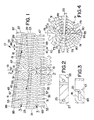
- Figure 1 is a fragmentary plan view of a first embodiment of a conveyor incorporating various of the features of the invention.
- Figure 2 is a sectional view taken along line 2--2 of Figure 1.
- Figure 3 is a sectional view taken along line 3--3 of Figure 1.
- Figure 4 is a fragmentary, enlarged, and broken-away view of a center portion of the conveyor shown in Figure 1.
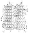
- Figure 5 is a fragmentary plan view of a second embodiment of a conveyor which incorporates various of the features of the invention and which is shown in a straight forward movement condition.
- Figure 6 is a view which is similar to Figure 5 and which shows the conveyor of Figure 5 in a side-flexure movement condition.
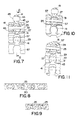
- Figure 7 is a fragmentary, enlarged, and partially broken-away view of an intermediate portion of the conveyor shown in Figures 5 and 6.
- Figure 8 is a sectional view taken along line 8--8 of Figure 7.
- Figure 9 is a sectional view taken along line 9--9 of Figure 5.
- Figure 10 is a fragmentary, enlarged, and partially broken-away view of another intermediate portion of the conveyor shown in Figures 5 and 6.
- Figure 11 is a fragmentary, enlarged, and partially broken-away view of still another intermediate portion of the conveyor shown in Figures 5 and 6.
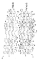
- Figure 12 is a fragmentary plan view of a third embodiment of a conveyor which incorporates various of the features of the invention and which is shown in straight forward movement condition.
- Figure 13 is a view which is similar to Figure 12 and which shows the conveyor of Figure 12 in a side-flexure movement condition.
- Figure 14 is a fragmentary, enlarged, and partially broken-away view of an end portion of the conveyor shown in Figures 12 and 13.
- Figure 15 is a sectional view taken along line 15--15 of Figure 12.
- Figure 16 is a sectional view taken along line 16--16 of Figure 12.
- Figure 17 is a fragmentary plan view of a fourth embodiment of a conveyor which incorporates various of the features of the invention and which is shown in straight forward movement condition.
- Figure 18 is a view which is similar to Figure 17 and which shows the conveyor of Figure 17 in side-flexure movement condition.
- Figure 19 is a fragmentary, enlarged, and partially broken-away view of an end portion of the conveyor shown in Figures 17 and 18.
- Figure 20 is a sectional view taken along line 20--20 of Figure 17.
- Figure 21 is a sectional view taken along line 21--21 of Figure 17.
- first, second, third, and fourth modular conveyors or link belts or chains 111, 211, 311, and 411 are respectively intended for travel along intended directions of conveyor movement on given paths having a central axis or center line 19.
- the first, second, third, and fourth modular conveyors or link belts or chains 111, 211, 311, and 411 respectively have laterally spaced and opposed sides 21 and 23, and have side-flexing capability.
- Each of the first, second, third, and fourth conveyors or link belts or chains 111, 211, 311, and 411 comprises a plurality of chain or hinge pins 25 which pivotally and serially interconnect a plurality of (one type of) link module including a first link module 27 and a second link module 29.
- the first link module 27 and the second link module 29 include a first plurality of laterally spaced eyes 31 which extend along the intended direction of conveyor travel and which respectively have therein laterally aligned first bores 33 receiving one of the chain pins 25.
- Each of the first plurality of eyes 31 has a first side portion or edge surface 35.
- Both link modules 27 and 29 include a second plurality of laterally spaced eyes 41 which are laterally offset from the first plurality of eyes 31, which extend in the direction opposite to the direction of extension of the first plurality of eyes 31, which respectively have therein laterally aligned second bores 43 receiving the before mentioned one chain pin 25, and which define therebetween a plurality of spaces 47 which loosely receive the first plurality of eyes 31.
- Each one of the second plurality of eyes 41 includes a second side portion or edge surface 45 which is located for interfering engagement with the first side portion or edge surface 35 in the intended direction of conveyor travel so as to transmit tension or load between the first and second link modules 27 and 29 in the intended direction of conveyor movement or travel.
- the transmission of tension or load between the first and second link modules 27 and 29 occurs independently of the receipt of the chain pin 25 in the bores 33 and 43 of the first and second plurality of eyes 31 and 41, and the receipt of the chain pin 25 in the first and second plurality of eyes 31 and 41 prevents disengagement of the first and second plurality of eyes 31 and 41, and, hence, the first and second link modules 27 and 29, from each other.
- At least one eye of the first plurality of eyes 31 and one eye of the second plurality of eyes 41 are located for interfering engagement with each other in a direction transverse to the intended direction of conveyor movement or travel so as to prevent substantial movement between the first and second link modules 27 and 29 in the direction transverse to the intended direction of conveyor movement or travel.
- the link modules 27 and 29 can be fabricated from any suitable material in any suitable way. However, in the disclosed embodiments, the link modules 27 and 29 are both preferably molded of relatively hard plastic in a generally identical configuration or shape.
- the chain or hinge pins 25 can be constructed of any suitable material.
- the link modules (including the first and second link modules 27 and 29) of the first conveyor or link belt 111 each include a spine portion 51 which generally extends the full width of the first conveyor or link belt 111, and which interconnects the first and second pluralities of eyes 31 and 41. While other constructions can be employed, in the first conveyor or link belt 111, the spine portion 51 includes laterally opposite first and second side portions 53 and 55 which extend laterally in both directions from the center line or central axis 19, and, adjacent the conveyor sides 21 and 23, curve somewhat in the intended direction of conveyor movement or travel, either forwardly or rearwardly.
- Each of the link modules of the first conveyor or link belt 111 includes both the before mentioned first and second pluralities of eyes 31 and 41, as well as the plurality of spaces 47 defined between the second plurality of eyes 41, and another plurality of spaces 57 which are defined between the first plurality of eyes 31, and which receive another plurality of eyes (corresponding to the before mentioned second plurality of eyes) of another adjacent link module.
- the first plurality of eyes 31 extend from the first spine side portion 53 in respective arcs respectively defined by radii 59 which extend from a common center 61 located on the center line 19, and which are of progressively greater length in accordance with increased spacing of the eyes 31 from the center line 19.
- each of the first plurality of eyes 31 respectively includes a laterally spaced pair of the before mentioned side portions or edge surfaces 35 which extend arcuately.
- the first plurality of eyes 31 includes a first series 65 of eyes extending on one side of the center line 19 in arcuately concave relation to the center line 19, and a second series 67 of eyes extending on the other side of the center line 19 in arcuately concave relation to the center line 19 and in opposing relation to the first series 65 of eyes.
- the eyes 31 of the first and second series 65 and 67 respectively include transversely extending outer end surfaces or edges 69 which are transversely aligned with each other.
- the arcuately extending eyes 31 of the first plurality have a first radially extending width 70 and are respectively transversely spaced from one another at given distances.
- the first plurality of eyes 31 also includes (see Figure 4) a center eye 71 projecting along the center line 19 and including a stem portion 73, and a truncated circular ring portion 75 extending from the stem portion 73 and including two laterally spaced branches 77 each including a laterally spaced pair of the before mentioned side portions or edge surfaces 79 defined by radii extending from the common point 61, and laterally aligned end surfaces or edges 80 which are aligned with the end surfaces 69.
- the bores 33 of the first link module 27 are tapered or flared and the bores 43 of the second link module 29 are cylindrical.
- the bores 43 can be flared or elongated and the bores 33 can be cylindrical.
- the second plurality of laterally spaced eyes 41 of the first conveyor or link belt 111 are laterally offset from the first plurality of eyes 31, extend from the spine portion 51 in the direction opposite to the direction of extension of the first plurality of eyes 31, and respectively extend in arcs respectively defined by radii 81 extending from the center 61 located on the center line 19.
- each of the second plurality of eyes 41 respectively also includes a laterally spaced pair of the before mentioned side portions or edge surfaces 45 which extend arcuately.
- the second plurality of eyes 31 includes a first series 85 of eyes extending on one side of the center line 19 in arcuately concave relation to the center line 19 and a second series 87 of eyes extending on the other side of the center line 19 in arcuately concave relation to the center line and in opposing relation to the first series 85 of eyes.
- the eyes 41 of the second plurality respectively also include laterally aligned, transversely extending outer end surfaces or edges 89 which extend at increasing distances from the spine portion 51 in accordance with increased spacing of the eyes 41 from the center line 19 and which are transversely aligned with each other.
- the second plurality of eyes 41 also includes (see Figure 4) a center or middle eye 91 projecting along the center line 19 and including a stem portion 93, and a truncated circular portion 95 extending from the stem portion 93 and including an end surface or edge 97 laterally aligned with the outer end surfaces or edges 89 of the first and second series 85 and 87, and a pair of laterally spaced circular side portions or edge surfaces 99.
- the second plurality of eyes 41 has a second radially extending width 98 about equal to the radial width 70 of the eyes 31 of the first plurality and also define therebetween the before mentioned plurality of spaces 47 which extend arcuately in spaced relation to one another, which are slightly larger than the radial width 70 of the first plurality of eyes 31, and which loosely receive the first plurality of eyes 31 with the side portions or edge surfaces 35 and 45 of the first and second plurality of eyes 31 and 41 (and the side portions or edge surfaces 79 and 99) located for interfering engagement in the intended direction of conveyor movement so as to transmit tension between the first and second link modules 27 and 29 in the direction of intended conveyor movement.
- the connected link modules 27 and 29 can swivel or side-flex relative to one another about the center 61, while, at the same time, the side portions or edge surfaces 35 and 45 thereof (and the side portions or edge surfaces 79 and 99) are located for abutting and interfering engagement in the intended direction of conveyor travel so as to transmit tension or load between the first and second link modules 27 and 29 along the given path, i.e., in the intended direction of conveyor travel.
- Such tension or load is transmitted at laterally spaced intervals along the entire width of the conveyor or belt 111, notwithstanding side-flexing (and also during straight forward movement), due to abutting and interfering engagement therebetween in the direction of conveyor movement of the side portions or edge surfaces 35 and 45 (and the side portions or edge surfaces 79 and 99) of the first and second plurality of eyes 31 and 41, and generally independently of the receipt of the chain pin or hinge pin 25 in the aligned bores 33 and 43.
- Such abutting and interfering engagement also prevents withdrawal of the eyes 31 from the spaces 47 in response to the application of load or tension in the intended direction of conveyor travel.
- At least one of the aligned first and second (series of) bores 33 and 43 is generally cylindrical in shape (the bores 33 in the disclosed construction) and the other of the aligned first and second (series of) bores 33 and 43 is elongated in the direction of intended conveyor travel (the bores 43 in the disclosed construction) so as to accommodate conveyor side-flexure.
- the length of the elongation of the series of bores 43 becomes progressively larger in accordance with the spacing of the eyes 41 from the center line 19, thereby enabling the chain 111 to side-flex or swivel about the center 61.
- the underside of at least one of the first plurality of eyes 31 includes a driving recess defined by a surface 101 adapted to receive the teeth of a driving sprocket (not shown).
- the link modules (including the first and second link modules 27 and 29) each include a spine portion 51 which generally extends the full width of the conveyor or link belt 211, and which interconnects the first and second pluralities of eyes 31 and 41.
- Each of the link modules 27 and 29 includes both the before mentioned first and second pluralities of eyes 31 and 41, as well as the plurality of spaces 47 defined between the second plurality of eyes 41, and another plurality of spaces 57 which are defined between the first plurality of eyes 31, and which receive another plurality of eyes (corresponding to the before mentioned second plurality of eyes) of another adjacent link module.
- the second plurality of eyes 41 include a stem or neck portion 221 having a transverse width 223, and a main or circular portion 225 having a maximum lateral or transverse width 227 substantially greater than the width 223 of the neck or stem portion 221, and a laterally spaced pair of the before mentioned side portions or edge surfaces 45 which are generally outwardly convex in shape.
- the first plurality of eyes 31 are generally of identical shape and include outwardly concave side portions or edge surfaces 35 defining partially circular spaces 57 which are somewhat larger than the eyes 41.
- the spaces 57 each include a central or main portion 231 which is defined by a laterally spaced pair of the before mentioned generally outwardly concave side portions or edge surfaces 35.
- the main portion 231 has a maximum width 233 and receives the main portion 225 of the associated one of the plurality of eyes 41.
- the spaces 57 each include an entry neck or opening 235 which communicates with the main portion 231, which receives the stem or neck portion 221 of the associated eye 41, and which has a lateral width 237 less than the maximum transverse width 227 of the main portion 225 of the eye 41.
- the connected link modules 27 and 29 can swivel or side-flex relative to one another from either of the conveyor sides 21 or 23, while, at the same time, the side portions or edge surfaces thereof 35 and 45 are located for abutting and interfering engagement therebetween in the intended direction of conveyor travel (and in position to prevent escape from such relation consequent to either forward or side-flexing movement in the plane of intended conveyor movement) and so as thereby to transmit tension or load between the first and second link modules 27 and 29 along the given path, i.e., in the intended direction of conveyor travel.
- Such tension or load is transmitted at multiple laterally spaced intervals along the entire width of the conveyor or belt or chain 211, notwithstanding side-flexing (or during straight forward movement) due to the interfering engagement in the direction of conveyor movement of the side portions or edge surfaces 35 and 45 of the first and second plurality of eyes 31 and 41 and generally independently of the receipt of the chain pin or hinge pin 25 in the aligned bores 33 and 43.
- At least one of the aligned first and second (series of) bores 33 and 43 is generally cylindrical in shape and the other of the aligned first and second (series of) bores 33 and 43 is elongated in the direction of intended conveyor travel so as to accommodate conveyor side-flexure.
- both series of bores 33 and 43 are elongated so as to enable the conveyor or belt or chain 211 to side-flex or swivel from either of the conveyor sides 21 and 23.
- both series of bores 33 and 43 are elongated (at a common length) in the intended direction of conveyor travel.
- the underside of at least one of the first plurality of eyes 31 includes a driving recess defined by a surface 301 adapted to receive the teeth of a driving sprocket (not shown).
- the link modules each include a spine portion 51 which, while other constructions can be employed, extends generally the full width of the third conveyor or link belt or chain 311 and in generally perpendicular relation to the center line 19, which interconnects the first and second pluralities of eyes 31 and 41, and which includes, on one side of the center line 19, a first spine side portion 53, and, on the other side of the center line 19, a second spine side portion 55.
- Each of the link modules 27 and 29 of the third conveyor or link belt or chain 311 includes both the before mentioned first and second pluralities of eyes 31 and 41, as well as the plurality of spaces 47 defined between the second plurality of eyes 41, and another plurality of spaces 57 which are defined between the first plurality of eyes 31, and which receive another plurality of eyes (corresponding to the before mentioned second plurality of eyes) of another adjacent link module.
- the first and second plurality of eyes 31 and 41 respectively also include laterally aligned first and second bores 33 and 43 receiving one of the chain pins 25.
- the first plurality of eyes 31 includes a first series 65 of eyes extending from the first spine side portion 53 on one side of the center line 19 and in the direction away from the spine portion 51 and toward the center line 19 and which are defined, at least in part, by the before mentioned side portions or edge surfaces 35 which extend in generally laterally spaced and generally parallel relation to one another and in inclined relation away from the spine portion 51 and toward the center line 19.
- One of the side portions or edge surfaces 35 of each of the eyes in the first series 65 is connected to the first spine side portion 53 by a connecting edge portion or surface 321 which is preferably arcuate or curved and which extends in convexly facing relation to the center line 19.
- the other one of the side portions or edge surfaces 35 of each eye in the first series 65 is connected to the first spine side portion 53 by a connecting edge portion or surface 323 which extends at an obtuse angle to the spine side portion 53 and merges into the connected side portion or edge surface 35.
- the first series 65 of eyes of the first plurality of eyes 31 also includes an eye 341 located in spaced, adjacent relation to the center line 19 and having a side portion or edge surface 97 which is located adjacent the center line 19.
- the first plurality of eyes 31 also includes a second series 67 of eyes extending from the second spine side portion 55 on the other side of the center line 19 and in the direction away from the spine portion 51 and toward the center line 19 and which are defined by laterally spaced, and generally parallel side portions or edge surfaces 35 which are inclined away from the spine portion 51 and toward the center line 19.
- One of the side portions or edge surfaces 35 of each of the eyes in the second series 67 is connected to the second spine side portion 55 by a connecting edge portion or surface 331 which is preferably arcuate or curved and extends in convexly facing relation to the center line 19.
- the other one of the side portions or edge surfaces 35 of each eye in the second series 67 is connected to the second spine side portion 55 by a connecting edge portion or surface 333 which extends at an obtuse angle to the spine side portion 55 and merges into the connected side portion or edge surface 35.
- the second series 67 of eyes of the first plurality of eyes 31 also includes an eye 351 located in spaced and adjacent relation to the center line 19 and having a side portion or edge surface 97 which is located adjacent the center line 19 and which, together with the side portion or edge surface 97 of the eye 341, define a center or middle space 361.
- the second plurality of eyes 41 includes a first series 85 of eyes which are located on one side of the center line 19, which extend from the first spine side portion 53 in the opposite direction from the first series 65 of the first plurality of eyes 31 and in inclined relation to the center line 19 and which are defined, at least in part, by the before mentioned side portions or edge surfaces 45 which extend in generally laterally spaced and generally parallel relation to one another and in inclined relation away from the spine portion 51 and toward the center line 19. While other constructions can be employed, in this disclosed embodiment, the first series 85 of eyes of the second plurality of eyes 41 are laterally spaced from each other at generally common distances and have generally common lateral widths.
- One of the side portions or edge surfaces 45 of each of the eyes in the first series 85 of eyes is connected to the first spine side portion 53 by a connecting edge portion or surface 341 which is preferably arcuate or curved and which extends in concavely facing relation to the center line 19.
- the other one of the side portions or edge surfaces 45 of each eye in the first series 85 is connected to the first spine side portion 53 by a connecting edge portion or surface 343 which extends at an acute angle to the spine side portion 53 and in inclined relation to, and at an obtuse angle to, the connected side portion 45.
- the second plurality of eyes 41 of the conveyor or belt or chain 311 includes a second series 87 of eyes which are located on the other side of the center line 19, and which extend from the second spine side portion 55 in the opposite direction from the second series 67 of the first plurality of eyes 31 and in inclined relation to the center line in the opposite sense from the first series 85 of eyes. While other constructions can be employed, in the conveyor 311, the second series 87 of eyes of the second plurality of eyes 41 are laterally spaced from each other at generally common distances and have generally common lateral widths.
- One of the side portions or edge surfaces 45 of each of the eyes in the second series 87 is connected to the second spine side portion 55 by a connecting edge portion or surface 341 which is preferably arcuate or curved and extends in concavely facing relation to the center line 19.
- the other one of the side portions or edge surfaces 45 of each eye in the second series 87 is connected to the second spine side portion 55 by a connecting edge portion or surface 343 which extends at an acute angle to the spine side portion 55 and in inclined relation to, and at an obtuse angle to, the connected side portion 45.
- the second plurality of eyes 41 of the conveyor 311 includes a center or middle eye 71 which projects along the center line 19 and which is loosely received in the space 361.
- the center eye 71 includes an outer transverse end or edge surface 77, and a pair of laterally spaced converging side portions or edge surfaces 79 which extend between the spine portion 51 and the outer end or edge surface 77 and which engage the side portions or edge surfaces 97 of the eyes 341 and 351 of the first plurality of eyes 31.
- the spaces 47 and 361 respectively receive the eyes 31 and the center eye 71 in such manner as to locate the side portions or edge surfaces 35 and 45 (and the side portions or edge surfaces 79 and 97) for abutting and interfering engagement in the intended direction of conveyor travel so as to transmit tension or load between the link modules 27 and 29 along the given path, i.e., in the intended direction of conveyor travel.
- Such load or tension is transmitted at laterally spaced intervals along the entire width of the conveyor or belt 311, notwithstanding side-flexing, (and during straight forward conveyor movement), due to the interfering engagement in the direction of conveyor movement of the side portions or edge surfaces 35 and 45 (and the side portions or edge surfaces 79 and 97) of the first and second plurality of ears 31 and 41 and independently of the receipt of the associated one of the chains pin 25 in the first and second plurality of eyes 31 and 41.
- the respective side portions or edge surface 35 of each eye of the first plurality of eyes 31 include an adjacent side portion or edge surface 371 which is located adjacent to the center line 19 and which includes an outer end 373, and a remote side portion or edge surface 375 which is located remotely from the center line 19 and which includes an outer end 377.
- the respective side portions 45 of each eye of the second plurality of eyes 41 include an adjacent side portion or edge surface 372 which is located adjacent to the center line 19 and which includes an outer end 374, and a remote side portion or edge surface 376 which is located remotely from the center line 19 and which includes an outer end 378.
- the outer ends 373 of the adjacent side portions 371 of the first plurality of eyes 31 are located at respective first given distances 381 (one shown) from the center line 19, whereas the outer ends 378 of the remote side portions 376 of the inwardly adjacent eye of the second plurality of eyes 41 are located at a second given distance 383 from the center line 19 less than the first given distance 381 so that the outer ends 377 of the remote side portions 375 of the first plurality of eyes 31 are located, with respect to the outer ends 378 of the remote side portions 376 of the second plurality of eyes 41, in position for abutting and interfering engagement therebetween in the direction of conveyor travel (and in position to prevent escape from such relation consequent to either forward or side-flexing movement in the plane of intended conveyor movement) and so as thereby to transmit tension or load between the connected link modules 27 and 29 in the intended direction of conveyor travel.
- first and second transversely aligned series of bores 33 and 43 is elongated in the direction of intended conveyor travel to accommodate side-flexing of the conveyer 311. While other constructions can be employed, in the conveyor 311, the bores 43 are of generally constant diameter, and the bores 33 are elongated in the direction of conveyor travel at a generally common distance to accommodate pivoting or side-flexing of the conveyor about either of the conveyor sides 21 and 23.
- At least one of the eyes of the first plurality of eyes 31 and one of eyes of the second plurality of eyes 41 are located for interfering engagement with each other in a direction transverse to the intended direction of conveyor movement so as to prevent substantial movement therebetween in the direction transverse to the direction of intended conveyor movement.
- the underside of at least one of the first plurality of eyes 31 includes a driving recess including a surface 381 adapted to be engaged by the teeth of a driving sprocket (not shown).
- the first plurality of eyes 31 of one of the link modules 27 and 29 are received in the plurality of spaces 47 defined by the second plurality of eyes 41 on the adjacent link module in such manner as to locate the eye side portions or edge surfaces 35 and 45 for interfering engagement in the direction of intended conveyor travel so as to transmit tension or load therebetween along the given path, i.e., in the direction of intended conveyor travel.
- Such tension or load is transmitted at several laterally spaced intervals or locations along the width of the conveyor or belt or chain 311, notwithstanding side-flexing (or straight forward movement), due to the interfering engagement in the direction of conveyor movement of the side portions or edge surfaces of the first and second plurality of eyes 31 and 41 and independently of the receipt of the associated one of the chain pins 25 in the first and second plurality of eyes 31 and 41.
- the link modules each include a spine portion 51 which generally extends the full width of the fourth conveyor or link belt 411, and which interconnects the first and second pluralities of eyes 31 and 41. While other constructions can be employed, in the fourth conveyor or link belt 411, the spine portion 51 includes first and second opposite side portions 53 and 55 which extend laterally in both directions from the center line or central axis 19 and in converging, inclined relation to the central axis.
- Each of the link modules of the fourth conveyor or link belt or chain 411 includes both the before mentioned first and second pluralities of eyes 31 and 41, as well as the plurality of spaces 47 defined between the second plurality of eyes 41, and another plurality of spaces 57 which are defined between the first plurality of eyes 31, and which receive another plurality of eyes (corresponding to the before mentioned second plurality of eyes) of another adjacent link module.
- the first and second plurality of eyes 31 and 41 respectively include transversely aligned first and second bores 33 and 43 receiving one of the chain pins 25.
- the first plurality of eyes 31 of the fourth conveyor or belt or chain 411 includes a first series 65 of eyes which extend from the first spine side portion 53, on one side of the center line 19, and along the intended direction of conveyor travel.
- the first series of eyes 65 of the first plurality of eyes 31 includes an inner eye 421 located in spaced relation to the center line 19, an outer eye 423 located adjacent the conveyor side 21, and one or more intermediate eyes 425 located intermediate the inner and outer eyes 421 and 423 and in spaced relation to one another and to the inner and outer eyes 421 and 423 to define therebetween a series of spaces 57.
- the first plurality of eyes 31 also includes a second series of eyes 67 which extend from the second spine side portion 55 on the other side of the center line 19 and along the intended direction of conveyor travel and which include an inner eye 431 located in spaced relation to the center line 19, an outer eye 433 adjacent the conveyor side 23, and one or more intermediate eyes 435 located intermediate the inner and outer eyes 431 and 433 and in spaced relation to one another and to the inner and outer eyes 431 and 433 to define therebetween a series of spaces 57.
- a second series of eyes 67 which extend from the second spine side portion 55 on the other side of the center line 19 and along the intended direction of conveyor travel and which include an inner eye 431 located in spaced relation to the center line 19, an outer eye 433 adjacent the conveyor side 23, and one or more intermediate eyes 435 located intermediate the inner and outer eyes 431 and 433 and in spaced relation to one another and to the inner and outer eyes 431 and 433 to define therebetween a series of spaces 57.
- the eyes of the first and second series 65 and 67 of the first plurality of eyes 31 are defined, in part, by side surfaces 441 located in transversely spaced and laterally aligned relation to one another.
- the side surfaces 441 include inner portions 443 which constitute the before mentioned side portions or edge surfaces 35, which can be straight or slightly curved, which extend in inclined relation from the spine portion 51 in acute angular relation thereto, and which have respective outer ends 445 located at respective distances 446 from a common center 447 located on the center line 19 in spaced relation from a center eye 71 (still to be described) in the direction away from the link module.
- the side surfaces 441 also include respective outer curved portions 449 which respectively extend from the outer ends 445 of the inner portions 443 and which are defined by respective radii 446 extending from the common point 447.
- the first plurality of eyes 31 also includes a center eye 71 projecting along the center line 19 from the spine portion 51 in the same direction as the first and second series 65 and 67 of the first plurality of eyes 31 and includes an outer end or edge surface 77, and a pair of laterally spaced arcuate outwardly convex side portions or edge surfaces 79 which extend between the spine portion 51 and the outer end or edge surface 77.
- the second plurality of eyes 41 includes a first series of eyes 85 which extends from the first spine side portion 53 in the direction opposite to the direction of extension of the first series 65 of the first plurality of eyes 31 and on the one side of the center line 19 and along the intended direction of conveyor travel.
- the first series of eyes 85 include an inner eye 461 located adjacent the center line 19, an outer eye 463 located adjacent the conveyor side 21, and one or more intermediate eyes 465 located intermediate the inner and outer eyes 461 and 463 and in spaced relation to one another and to the inner and outer eyes 461 and 463 to define therebetween the spaces 47.
- the second plurality of eyes 41 of the conveyor or belt or chain 411 also includes a second series 87 of eyes which extend from the spine side portion 55 in the direction opposite to the direction of extension of the second series 67 of the first plurality of eyes 31 and on the other side of the center line 19 and along the direction of intended conveyor travel.
- the second series 87 of eyes include an inner eye 462 located adjacent the center line 19, an outer eye 464 located adjacent the conveyor side 23, and one or more intermediate eyes 466 located intermediate the inner and outer eyes 462 and 464 and in spaced relation to one another and to the inner and outer eyes 462 and 464 to define therebetween the spaces 47.
- the inner eyes 461 and 462 of the first and second series 85 and 87 of the second plurality of eyes 41 of the fourth conveyor, belt, or chain 411 are generally of identical shape (except for being left and right handed) and respectively include outer end portions 471 defined by respective outer end or edge surfaces 473, and by side portions or edge surfaces 35 which arcuately respectively extend from the laterally spaced ends of the outer end or edge surfaces 471 toward the spine portion 51.
- the inner eyes 461 and 462 of the first and second series 85 and 87 of the second plurality of eyes 41 of the fourth conveyor, belt, or chain 411 also respectively include neck portions 475 which extend between the spine portion 51 and the outer end portions 471, which taper toward the spine portion 51, and which, in general, are of lesser transverse width than the outer end portions 471.
- the inner eyes 461 and 462 of the first and second series 85 and 87 of eyes of the second plurality of eyes 41 of the fourth conveyor, belt, or chain 411 define a center space 479 which is located along the center line 19 and which is bordered by the side portions or edge surfaces 461 and 462.
- the outer eyes 463 and 464 of the first and second series 85 and 87 of the second plurality of eyes 41 of the fourth conveyor, belt, or chain 411 are generally of identical shape (except for being left and right handed) and respectively include outer end portions 481 defined by respective outer end or edge surfaces 483, and by arcuate side portions or surface edges 45 which respectively extend from the laterally spaced ends of the outer end or edge surfaces 483 toward the spine portion 51.
- the outer eyes 463 and 464 of the first and second series 85 and 87 of the second plurality of eyes 41 of the fourth conveyor, belt, or chain 411 also respectively include neck portions 485 which extend between the spine portion 51 and the outer end portions 451, which taper toward the spine portion 51, and which, in general, are of lesser transverse width than the outer end portions 451.
- the intermediate eyes 465 and 466 of the first and second series 85 and 87 of the second plurality of eyes 41 of the fourth conveyor, belt, or chain 411 are generally of identical shape (except for being left and right handed), and respectively include outer end portions 487 defined by respective arcuate outer end or edge surfaces 489 which extend for more than 180 degrees, and neck portions 491 which extend between the spine portion 51 and the outer end portions 487, which taper toward the spine portion 51, and which, in general, are of lesser transverse width than the outer end portions 487.
- Respectively defined between the inner eyes 461 and 462 and the intermediate eyes 465 and 466, and between adjacent intermediate eyes 465 and 466, and between the intermediate eyes 465 and 466 and the outer eyes 463 and 464 of the first and second series 85 and 87 of eyes of the second plurality of eyes 41 are respective spaces 47 adapted to receive the first plurality of eyes of an another link module.
- first and second transversely aligned series of bores 33 and 43 is elongated in the direction of intended conveyor travel to accommodate side-flexing of the conveyer. While other constructions can be employed, in the conveyor 411, the bores 33 are of generally constant diameter, and the bores 43 are elongated or flared in the direction of conveyor travel to accommodate pivoting or side-flexing of the conveyor about the center line 19.
- the underside of at least one of the first plurality of eyes 31 includes a driving recess including a surface 481 adapted to be engaged by the teeth of a driving sprocket (not shown).
- the first plurality of eyes 31 of one of the link modules 27 and 29 are received in the plurality of spaces 47 defined by the second plurality of eyes 41 on the adjacent link module in such manner as to locate the eye side portions or edge surfaces 35 and 45 for abutting and interfering engagement in the direction of intended conveyor travel (and in position to prevent escape from such relation consequent to either forward or side-flexing movement in the plane of intended conveyor movement) so as thereby to transmit tension or load therebetween along the given path, i.e., in the direction of intended conveyor travel.
- Such tension or load is transmitted at several laterally spaced intervals or locations along the width of the conveyor or belt or chain 411, notwithstanding side-flexing (or straight forward movement), due to the interfering engagement in the direction of conveyor movement of the side portions of the first and second plurality of eyes 31 and 41 and independently of the receipt of the associated one of the chain pins 25 in the first and second plurality of eyes 31 and 41.
- At least one eye of the first plurality of eyes 31 and one eye of the second plurality of eyes 41 are located for interfering engagement with each other in a direction transverse to the direction of intended conveyor movement so as to prevent substantial movement therebetween in the direction transverse to the direction of intended conveyor movement.
- One of the advantages of the invention is that the disclosed chain, belt, or conveyor construction can be manufactured with greater width because the chain, belt, or conveyor transfers tension or load at multiple places transversely of the chain, belt, or conveyor and is not limited by pin strength.
- Another particular and especially important advantage of the disclosed invention is that a single side-flexing conveyor, belt, or chain as disclosed herein can replace a multiple strand conveyor, belt, or chain.
- the disclosed conveyor,belt, or chain (with the curved or inclined interfering side portions or edge surfaces) is not limited to load transfer at the sides of the chain, belt, or conveyor, and through the hinge pin, as referred to above.
- the eyes are curved or inclined and intermesh together, adjacent link modules mate together so as to carry the load or tension at multiple places throughout the width of the chain, belt, or conveyor during side-flex.
- the curved eyes have incremental radii starting from a center on the center line to insure positive interaction during side-flexure.
- the link modules will not expand and contract in straight forward movement or running because the curved or inclined eyes interfere to keep the chain, belt, or conveyor running straight and at a constant pitch.
- the disclosed chain, belt, or conveyor can carry the load or tension in two forms.
- the curved or inclined eyes equally distribute the load across the remainder of the link modules to provide for an equally distributed load.
- the hinge pin can be placed in shear at an outer side of the link modules in a manner similar to previous designs.
- the load can be transferred from one link module to the next by transferring load through the side portions (as fully explained above) and also by transferring load from one link module to the connecting hinge pin and from the connecting hinge pin to the next link module.
- the curved or inclined eye design provides a chain, belt, or conveyor which tracks better and which is stronger. Because the disclosed chains, belts, or conveyors involve equal loading across the width thereof, the disclosed chains, belts, or conveyors can carry heavier loads. In addition, the disclosed chains, belts, or conveyors perform better and track better because the they have a constant pitch.
Description
- The invention relates generally to modular conveyors (which term includes belts and chains) and, more particularly but not exclusively to such conveyors which include side-flexing capability, i.e. the ability to turn left or right in the plane of conveyor movement.
- In the past, side-flexing conveyors were limited in width and some of such prior side-flexing conveyors transferred the load in tension in the direction of intended conveyor travel only at the middle of the chain conveyor. Such conveyors undesirably experienced very heavy loading at the middle portion of the chain. Other prior side-flexing conveyors depended on the pins to carry the load from link to link, thereby placing a high shear load on the pins, and particularly at the ends thereof during side-flexing operation.
- Previous designs for side-flexing modular belting or chain involved simply forming slotted holes where the pin joins the links to allow side-flexure of the links in the direction of travel. These previous designs have several limitations. The first limitation is that, because of the slotted holes, the belt or chain can expand and compress. This elasticity requires tension to always be placed on the modular belting for proper running i.e., the belting was always preloaded for proper functionality.
- The second limitation is inherent in the prior designs and results in carrying of the entire load, when the chain is side-flexing, at the sides of the chain. Thus, the outer portion of the pin carries the entire load in side-flexing because the pin only contacts the links at that point.
- Attention is directed to the following U.S. Patents:
- 3,261,451, G.C. Roinestad, July 19, 1966
- 3,826,150, K.V. Palmaer, July 30, 1974
- 3,854,575, Fraioli, Sr., December 17, 1974
- 3,946,857, Fraioli, Sr., March 30, 1976
- 4,185,737, K. Blättermann, January 29, 1980
- 4,222,483, Wooton et al., September 16, 1980
- 4,276,980, Y. Oizumi, July 7, 1981
- 4,640,410, Palmaer et al., February 3, 1987
- 4,742,907, K.V. Palmaer, May 10, 1988
- 4,846,339, G. Roinestad, July 11, 1989
- 4,901,844, Palmaer et al., February 20, 1990
- 4,934,517, J.M. Lapeyre, June 19, 1990
- 5,181,601, Palmaer et al., January 26, 1993
- 5,224,583, Palmaer et al., July 6, 1993
- 5,310,046, Palmaer et al., May 10, 1994
- 5,372,248, P.L. Horton, December 13, 1994 Attention is also directed to the following foreign patents:
- 0427337, EP, May 15, 1991
- 1,312,301, Canada, May 1, 1993
-
- A conveyor having in combination the features according to the preamble of claim 1 is known for example from US 5,224,583.
- The present invention provides a conveyor for travel along an intended direction on a given path and having laterally spaced and opposed sides, said conveyor comprising a plurality of chain pins which pivotally and serially interconnect a plurality of link modules, each of the link modules including a first plurality of laterally spaced eyes extending in the intended travel direction which respectively have therein aligned first bores receiving one chain pin, and which define a series of spaces, and a second plurality of laterally spaced eyes which extend opposite to the intended travel direction and are received in the plurality of spaces between the fist plurality of laterally spaced eyes of the adjacent link module and which respectively have therein aligned second bores receiving said chain pin to prevent disconnection of said adjacent link module characterised in that each of said first plurality of laterally spaced eyes includes a first side portion, and wherein each of said second plurality of laterally spaced eyes includes a second side portion, and wherein said first and second said side portions are located for interfering engagement in the direction of intended conveyor travel so as to directly transmit tension in the direction of conveyor movement between adjacent link modules at laterally spaced multiple places between said conveyor sides said transmission of tension occurring independently of the receipt of said chain pin in said first and second plurality of eyes.
- Other features are disclosed in
claims 2 to 11 and those features and the advantages of the invention will become apparent to those skilled in the art upon review of the following detailed description, claims and drawings. - Figure 1 is a fragmentary plan view of a first embodiment of a conveyor incorporating various of the features of the invention.
- Figure 2 is a sectional view taken along
line 2--2 of Figure 1. - Figure 3 is a sectional view taken along
line 3--3 of Figure 1. - Figure 4 is a fragmentary, enlarged, and broken-away view of a center portion of the conveyor shown in Figure 1.
- Figure 5 is a fragmentary plan view of a second embodiment of a conveyor which incorporates various of the features of the invention and which is shown in a straight forward movement condition.
- Figure 6 is a view which is similar to Figure 5 and which shows the conveyor of Figure 5 in a side-flexure movement condition.
- Figure 7 is a fragmentary, enlarged, and partially broken-away view of an intermediate portion of the conveyor shown in Figures 5 and 6.
- Figure 8 is a sectional view taken along line 8--8 of Figure 7.
- Figure 9 is a sectional view taken along line 9--9 of Figure 5.
- Figure 10 is a fragmentary, enlarged, and partially broken-away view of another intermediate portion of the conveyor shown in Figures 5 and 6.
- Figure 11 is a fragmentary, enlarged, and partially broken-away view of still another intermediate portion of the conveyor shown in Figures 5 and 6.
- Figure 12 is a fragmentary plan view of a third embodiment of a conveyor which incorporates various of the features of the invention and which is shown in straight forward movement condition.
- Figure 13 is a view which is similar to Figure 12 and which shows the conveyor of Figure 12 in a side-flexure movement condition.
- Figure 14 is a fragmentary, enlarged, and partially broken-away view of an end portion of the conveyor shown in Figures 12 and 13.
- Figure 15 is a sectional view taken along
line 15--15 of Figure 12. - Figure 16 is a sectional view taken along line 16--16 of Figure 12.
- Figure 17 is a fragmentary plan view of a fourth embodiment of a conveyor which incorporates various of the features of the invention and which is shown in straight forward movement condition.
- Figure 18 is a view which is similar to Figure 17 and which shows the conveyor of Figure 17 in side-flexure movement condition.
- Figure 19 is a fragmentary, enlarged, and partially broken-away view of an end portion of the conveyor shown in Figures 17 and 18.
- Figure 20 is a sectional view taken along
line 20--20 of Figure 17. - Figure 21 is a sectional view taken along
line 21--21 of Figure 17. - Before one embodiment of the invention is explained in detail, it is to be understood that the invention is not limited in its application to the details of the construction and the arrangements of components set forth in the following description or illustrated in the drawings. The invention is capable of other embodiments and of being practiced or being carried out in various ways. Also, it is understood that the phraseology and terminology used herein is for the purpose of description and should not be regarded as limiting.
- Illustrated respectively in Figures 1, 5, 12, and 17 are first, second, third, and fourth modular conveyors or link belts or
chains center line 19. The first, second, third, and fourth modular conveyors or link belts orchains opposed sides chains pins 25 which pivotally and serially interconnect a plurality of (one type of) link module including afirst link module 27 and asecond link module 29. - The
first link module 27 and thesecond link module 29 include a first plurality of laterally spacedeyes 31 which extend along the intended direction of conveyor travel and which respectively have therein laterally aligned first bores 33 receiving one of the chain pins 25. Each of the first plurality ofeyes 31 has a first side portion oredge surface 35. - Both
link modules eyes 41 which are laterally offset from the first plurality ofeyes 31, which extend in the direction opposite to the direction of extension of the first plurality ofeyes 31, which respectively have therein laterally aligned second bores 43 receiving the before mentioned onechain pin 25, and which define therebetween a plurality ofspaces 47 which loosely receive the first plurality ofeyes 31. Each one of the second plurality ofeyes 41 includes a second side portion oredge surface 45 which is located for interfering engagement with the first side portion oredge surface 35 in the intended direction of conveyor travel so as to transmit tension or load between the first andsecond link modules - In the disclosed conveyors, the transmission of tension or load between the first and
second link modules chain pin 25 in thebores eyes chain pin 25 in the first and second plurality ofeyes eyes second link modules - In addition, in the disclosed conveyors, at least one eye of the first plurality of
eyes 31 and one eye of the second plurality ofeyes 41 are located for interfering engagement with each other in a direction transverse to the intended direction of conveyor movement or travel so as to prevent substantial movement between the first andsecond link modules - The
link modules link modules - The chain or hinge
pins 25 can be constructed of any suitable material. - More specifically, as particularly shown in Figures 1 through 4, the link modules (including the first and
second link modules 27 and 29) of the first conveyor or link belt 111 each include aspine portion 51 which generally extends the full width of the first conveyor or link belt 111, and which interconnects the first and second pluralities ofeyes spine portion 51 includes laterally opposite first andsecond side portions central axis 19, and, adjacent the conveyor sides 21 and 23, curve somewhat in the intended direction of conveyor movement or travel, either forwardly or rearwardly. - Each of the link modules of the first conveyor or link belt 111 includes both the before mentioned first and second pluralities of
eyes spaces 47 defined between the second plurality ofeyes 41, and another plurality ofspaces 57 which are defined between the first plurality ofeyes 31, and which receive another plurality of eyes (corresponding to the before mentioned second plurality of eyes) of another adjacent link module. - While other specific constructions can be employed, in the first conveyor or link belt 111, the first plurality of
eyes 31 extend from the firstspine side portion 53 in respective arcs respectively defined by radii 59 which extend from acommon center 61 located on thecenter line 19, and which are of progressively greater length in accordance with increased spacing of theeyes 31 from thecenter line 19. As already mentioned, in the first conveyor 111, each of the first plurality ofeyes 31 respectively includes a laterally spaced pair of the before mentioned side portions or edge surfaces 35 which extend arcuately. - More specifically, as shown best in Figures 1 and 4, the first plurality of
eyes 31 includes afirst series 65 of eyes extending on one side of thecenter line 19 in arcuately concave relation to thecenter line 19, and asecond series 67 of eyes extending on the other side of thecenter line 19 in arcuately concave relation to thecenter line 19 and in opposing relation to thefirst series 65 of eyes. Theeyes 31 of the first andsecond series - The
arcuately extending eyes 31 of the first plurality have a first radially extendingwidth 70 and are respectively transversely spaced from one another at given distances. - The first plurality of
eyes 31 also includes (see Figure 4) acenter eye 71 projecting along thecenter line 19 and including astem portion 73, and a truncatedcircular ring portion 75 extending from thestem portion 73 and including two laterally spacedbranches 77 each including a laterally spaced pair of the before mentioned side portions or edge surfaces 79 defined by radii extending from thecommon point 61, and laterally aligned end surfaces oredges 80 which are aligned with the end surfaces 69. - As shown, the
bores 33 of thefirst link module 27 are tapered or flared and thebores 43 of thesecond link module 29 are cylindrical. However, in an alternate construction, thebores 43 can be flared or elongated and thebores 33 can be cylindrical. - The second plurality of laterally spaced
eyes 41 of the first conveyor or link belt 111 are laterally offset from the first plurality ofeyes 31, extend from thespine portion 51 in the direction opposite to the direction of extension of the first plurality ofeyes 31, and respectively extend in arcs respectively defined byradii 81 extending from thecenter 61 located on thecenter line 19. As already mentioned, each of the second plurality ofeyes 41 respectively also includes a laterally spaced pair of the before mentioned side portions or edge surfaces 45 which extend arcuately. - More specifically, the second plurality of
eyes 31 includes afirst series 85 of eyes extending on one side of thecenter line 19 in arcuately concave relation to thecenter line 19 and asecond series 87 of eyes extending on the other side of thecenter line 19 in arcuately concave relation to the center line and in opposing relation to thefirst series 85 of eyes. Theeyes 41 of the second plurality respectively also include laterally aligned, transversely extending outer end surfaces oredges 89 which extend at increasing distances from thespine portion 51 in accordance with increased spacing of theeyes 41 from thecenter line 19 and which are transversely aligned with each other. - The second plurality of
eyes 41 also includes (see Figure 4) a center ormiddle eye 91 projecting along thecenter line 19 and including a stem portion 93, and a truncatedcircular portion 95 extending from the stem portion 93 and including an end surface or edge 97 laterally aligned with the outer end surfaces oredges 89 of the first andsecond series - The second plurality of
eyes 41 has a second radially extendingwidth 98 about equal to theradial width 70 of theeyes 31 of the first plurality and also define therebetween the before mentioned plurality ofspaces 47 which extend arcuately in spaced relation to one another, which are slightly larger than theradial width 70 of the first plurality ofeyes 31, and which loosely receive the first plurality ofeyes 31 with the side portions or edge surfaces 35 and 45 of the first and second plurality ofeyes 31 and 41 (and the side portions or edge surfaces 79 and 99) located for interfering engagement in the intended direction of conveyor movement so as to transmit tension between the first andsecond link modules - As a consequence of the arcuate shape of the
eyes 31 and thespaces 47 and the loose receipt of theeyes 31 in thespaces 47, theconnected link modules center 61, while, at the same time, the side portions or edge surfaces 35 and 45 thereof (and the side portions or edge surfaces 79 and 99) are located for abutting and interfering engagement in the intended direction of conveyor travel so as to transmit tension or load between the first andsecond link modules eyes hinge pin 25 in the aligned bores 33 and 43. Such abutting and interfering engagement also prevents withdrawal of theeyes 31 from thespaces 47 in response to the application of load or tension in the intended direction of conveyor travel. - While other constructions can be employed, in the
link modules bores 33 in the disclosed construction) and the other of the aligned first and second (series of) bores 33 and 43 is elongated in the direction of intended conveyor travel (thebores 43 in the disclosed construction) so as to accommodate conveyor side-flexure. In the conveyor or link belt 111, shown in Figure 1, the length of the elongation of the series ofbores 43 becomes progressively larger in accordance with the spacing of theeyes 41 from thecenter line 19, thereby enabling the chain 111 to side-flex or swivel about thecenter 61. Thus, in the specifically disclosed construction shown in Figures 1 through 4, and because tension or load, in the direction of intended conveyor travel, is transmitted between theinterdigitated eyes adjacent link modules hinge pin 25 due to the tension or load in the direction of chain travel. While the illustrated construction discloses thebores 33 as being cylindrical in shape and thebores 43 as being elongated in shape, if desired, thebores 33 can be elongated and thebores 43 can be cylindrical. Furthermore, if desired thebores - Any suitable arrangement can be employed to advance the first conveyor 111 along the associated given path. In the specifically disclosed construction, the underside of at least one of the first plurality of
eyes 31 includes a driving recess defined by a surface 101 adapted to receive the teeth of a driving sprocket (not shown). - As particularly shown in Figures 5 through 11, in the second conveyor or link belt or
chain 211, the link modules (including the first andsecond link modules 27 and 29) each include aspine portion 51 which generally extends the full width of the conveyor orlink belt 211, and which interconnects the first and second pluralities ofeyes - Each of the
link modules eyes spaces 47 defined between the second plurality ofeyes 41, and another plurality ofspaces 57 which are defined between the first plurality ofeyes 31, and which receive another plurality of eyes (corresponding to the before mentioned second plurality of eyes) of another adjacent link module. - While other specific constructions can be employed, in the second conveyor or
link belt 211, the second plurality ofeyes 41 include a stem orneck portion 221 having atransverse width 223, and a main orcircular portion 225 having a maximum lateral ortransverse width 227 substantially greater than thewidth 223 of the neck orstem portion 221, and a laterally spaced pair of the before mentioned side portions or edge surfaces 45 which are generally outwardly convex in shape. - While other specific constructions can be employed, in the second conveyor or
link belt 211, the first plurality ofeyes 31 are generally of identical shape and include outwardly concave side portions or edge surfaces 35 defining partiallycircular spaces 57 which are somewhat larger than theeyes 41. - The
spaces 57 each include a central ormain portion 231 which is defined by a laterally spaced pair of the before mentioned generally outwardly concave side portions or edge surfaces 35. Themain portion 231 has amaximum width 233 and receives themain portion 225 of the associated one of the plurality ofeyes 41. In addition, thespaces 57 each include an entry neck or opening 235 which communicates with themain portion 231, which receives the stem orneck portion 221 of the associatedeye 41, and which has alateral width 237 less than the maximumtransverse width 227 of themain portion 225 of theeye 41. - As a consequence of the circular shape of the
eyes 41 and thespaces 57, and the loose receipt of theeyes 41 in thespaces 57, and the lessertransverse neck width 237 as compared to themaximum eye width 227, theconnected link modules second link modules - Such tension or load is transmitted at multiple laterally spaced intervals along the entire width of the conveyor or belt or
chain 211, notwithstanding side-flexing (or during straight forward movement) due to the interfering engagement in the direction of conveyor movement of the side portions or edge surfaces 35 and 45 of the first and second plurality ofeyes hinge pin 25 in the aligned bores 33 and 43. - While other constructions can be employed, in the
link modules link belt 211, at least one of the aligned first and second (series of) bores 33 and 43 is generally cylindrical in shape and the other of the aligned first and second (series of) bores 33 and 43 is elongated in the direction of intended conveyor travel so as to accommodate conveyor side-flexure. In the conveyor orlink belt 211, shown in Figures 5 through 11, both series ofbores chain 211 to side-flex or swivel from either of the conveyor sides 21 and 23. In the specifically disclosed construction, and because tension or load, in the direction of intended conveyor travel, is transmitted between theinterdigitated eyes adjacent link modules bores - Any suitable arrangement can be employed to advance the
conveyor 211 along the associated given path. In the specifically disclosed construction, the underside of at least one of the first plurality ofeyes 31 includes a driving recess defined by asurface 301 adapted to receive the teeth of a driving sprocket (not shown). - As particularly shown in Figures 12 through 16, in the third conveyor or link belt or
chain 311, the link modules (including the first andsecond link modules 27 and 29) each include aspine portion 51 which, while other constructions can be employed, extends generally the full width of the third conveyor or link belt orchain 311 and in generally perpendicular relation to thecenter line 19, which interconnects the first and second pluralities ofeyes center line 19, a firstspine side portion 53, and, on the other side of thecenter line 19, a secondspine side portion 55. - Each of the
link modules chain 311 includes both the before mentioned first and second pluralities ofeyes spaces 47 defined between the second plurality ofeyes 41, and another plurality ofspaces 57 which are defined between the first plurality ofeyes 31, and which receive another plurality of eyes (corresponding to the before mentioned second plurality of eyes) of another adjacent link module. The first and second plurality ofeyes second bores - More specifically, and while other specific constructions can be employed, in the third conveyor or link belt or
chain 311, the first plurality ofeyes 31 includes afirst series 65 of eyes extending from the firstspine side portion 53 on one side of thecenter line 19 and in the direction away from thespine portion 51 and toward thecenter line 19 and which are defined, at least in part, by the before mentioned side portions or edge surfaces 35 which extend in generally laterally spaced and generally parallel relation to one another and in inclined relation away from thespine portion 51 and toward thecenter line 19. - One of the side portions or edge surfaces 35 of each of the eyes in the
first series 65 is connected to the firstspine side portion 53 by a connecting edge portion orsurface 321 which is preferably arcuate or curved and which extends in convexly facing relation to thecenter line 19. The other one of the side portions or edge surfaces 35 of each eye in thefirst series 65 is connected to the firstspine side portion 53 by a connecting edge portion orsurface 323 which extends at an obtuse angle to thespine side portion 53 and merges into the connected side portion oredge surface 35. - The
first series 65 of eyes of the first plurality ofeyes 31 also includes aneye 341 located in spaced, adjacent relation to thecenter line 19 and having a side portion oredge surface 97 which is located adjacent thecenter line 19. - In addition, in the conveyor or belt or
chain 311, the first plurality ofeyes 31 also includes asecond series 67 of eyes extending from the secondspine side portion 55 on the other side of thecenter line 19 and in the direction away from thespine portion 51 and toward thecenter line 19 and which are defined by laterally spaced, and generally parallel side portions or edge surfaces 35 which are inclined away from thespine portion 51 and toward thecenter line 19. - One of the side portions or edge surfaces 35 of each of the eyes in the
second series 67 is connected to the secondspine side portion 55 by a connecting edge portion orsurface 331 which is preferably arcuate or curved and extends in convexly facing relation to thecenter line 19. The other one of the side portions or edge surfaces 35 of each eye in thesecond series 67 is connected to the secondspine side portion 55 by a connecting edge portion orsurface 333 which extends at an obtuse angle to thespine side portion 55 and merges into the connected side portion oredge surface 35. - The
second series 67 of eyes of the first plurality ofeyes 31 also includes aneye 351 located in spaced and adjacent relation to thecenter line 19 and having a side portion oredge surface 97 which is located adjacent thecenter line 19 and which, together with the side portion oredge surface 97 of theeye 341, define a center ormiddle space 361. - In the third conveyor or link belt or
chain 311, the second plurality ofeyes 41 includes afirst series 85 of eyes which are located on one side of thecenter line 19, which extend from the firstspine side portion 53 in the opposite direction from thefirst series 65 of the first plurality ofeyes 31 and in inclined relation to thecenter line 19 and which are defined, at least in part, by the before mentioned side portions or edge surfaces 45 which extend in generally laterally spaced and generally parallel relation to one another and in inclined relation away from thespine portion 51 and toward thecenter line 19. While other constructions can be employed, in this disclosed embodiment, thefirst series 85 of eyes of the second plurality ofeyes 41 are laterally spaced from each other at generally common distances and have generally common lateral widths. - One of the side portions or edge surfaces 45 of each of the eyes in the
first series 85 of eyes is connected to the firstspine side portion 53 by a connecting edge portion orsurface 341 which is preferably arcuate or curved and which extends in concavely facing relation to thecenter line 19. The other one of the side portions or edge surfaces 45 of each eye in thefirst series 85 is connected to the firstspine side portion 53 by a connecting edge portion orsurface 343 which extends at an acute angle to thespine side portion 53 and in inclined relation to, and at an obtuse angle to, theconnected side portion 45. - The second plurality of
eyes 41 of the conveyor or belt orchain 311 includes asecond series 87 of eyes which are located on the other side of thecenter line 19, and which extend from the secondspine side portion 55 in the opposite direction from thesecond series 67 of the first plurality ofeyes 31 and in inclined relation to the center line in the opposite sense from thefirst series 85 of eyes. While other constructions can be employed, in theconveyor 311, thesecond series 87 of eyes of the second plurality ofeyes 41 are laterally spaced from each other at generally common distances and have generally common lateral widths. - One of the side portions or edge surfaces 45 of each of the eyes in the
second series 87 is connected to the secondspine side portion 55 by a connecting edge portion orsurface 341 which is preferably arcuate or curved and extends in concavely facing relation to thecenter line 19. The other one of the side portions or edge surfaces 45 of each eye in thesecond series 87 is connected to the secondspine side portion 55 by a connecting edge portion orsurface 343 which extends at an acute angle to thespine side portion 55 and in inclined relation to, and at an obtuse angle to, theconnected side portion 45. - Still further in addition, the second plurality of
eyes 41 of theconveyor 311 includes a center ormiddle eye 71 which projects along thecenter line 19 and which is loosely received in thespace 361. Thecenter eye 71 includes an outer transverse end oredge surface 77, and a pair of laterally spaced converging side portions or edge surfaces 79 which extend between thespine portion 51 and the outer end oredge surface 77 and which engage the side portions or edge surfaces 97 of theeyes eyes 31. - The
spaces eyes 31 and thecenter eye 71 in such manner as to locate the side portions or edge surfaces 35 and 45 (and the side portions or edge surfaces 79 and 97) for abutting and interfering engagement in the intended direction of conveyor travel so as to transmit tension or load between thelink modules belt 311, notwithstanding side-flexing, (and during straight forward conveyor movement), due to the interfering engagement in the direction of conveyor movement of the side portions or edge surfaces 35 and 45 (and the side portions or edge surfaces 79 and 97) of the first and second plurality ofears chains pin 25 in the first and second plurality ofeyes - More specifically, in the conveyor or belt or
chain 311, the respective side portions oredge surface 35 of each eye of the first plurality ofeyes 31 include an adjacent side portion oredge surface 371 which is located adjacent to thecenter line 19 and which includes anouter end 373, and a remote side portion oredge surface 375 which is located remotely from thecenter line 19 and which includes anouter end 377. In addition, in the conveyor or belt orchain 311, therespective side portions 45 of each eye of the second plurality ofeyes 41 include an adjacent side portion oredge surface 372 which is located adjacent to thecenter line 19 and which includes anouter end 374, and a remote side portion oredge surface 376 which is located remotely from thecenter line 19 and which includes anouter end 378. - In this regard, the outer ends 373 of the
adjacent side portions 371 of the first plurality ofeyes 31 are located at respective first given distances 381 (one shown) from thecenter line 19, whereas the outer ends 378 of theremote side portions 376 of the inwardly adjacent eye of the second plurality ofeyes 41 are located at a second givendistance 383 from thecenter line 19 less than the first givendistance 381 so that the outer ends 377 of theremote side portions 375 of the first plurality ofeyes 31 are located, with respect to the outer ends 378 of theremote side portions 376 of the second plurality ofeyes 41, in position for abutting and interfering engagement therebetween in the direction of conveyor travel (and in position to prevent escape from such relation consequent to either forward or side-flexing movement in the plane of intended conveyor movement) and so as thereby to transmit tension or load between theconnected link modules - Furthermore, as in the first and
second conveyors 111 and 211, in the conveyor or belt orchain 311, receipt of one of the chain pins 25 in the aligned bores 33 and 43 of the first and second plurality ofeyes eyes - One or both of the first and second transversely aligned series of
bores conveyer 311. While other constructions can be employed, in theconveyor 311, thebores 43 are of generally constant diameter, and thebores 33 are elongated in the direction of conveyor travel at a generally common distance to accommodate pivoting or side-flexing of the conveyor about either of the conveyor sides 21 and 23. - In addition, at least one of the eyes of the first plurality of
eyes 31 and one of eyes of the second plurality ofeyes 41 are located for interfering engagement with each other in a direction transverse to the intended direction of conveyor movement so as to prevent substantial movement therebetween in the direction transverse to the direction of intended conveyor movement. - Any suitable arrangement can be employed to advance the
third conveyor 311 along the associated given path. In the specifically disclosed construction, the underside of at least one of the first plurality ofeyes 31 includes a driving recess including asurface 381 adapted to be engaged by the teeth of a driving sprocket (not shown). - As in the other embodiments, in the third conveyor, belt, or
chain 311, the first plurality ofeyes 31 of one of thelink modules spaces 47 defined by the second plurality ofeyes 41 on the adjacent link module in such manner as to locate the eye side portions or edge surfaces 35 and 45 for interfering engagement in the direction of intended conveyor travel so as to transmit tension or load therebetween along the given path, i.e., in the direction of intended conveyor travel. Such tension or load is transmitted at several laterally spaced intervals or locations along the width of the conveyor or belt orchain 311, notwithstanding side-flexing (or straight forward movement), due to the interfering engagement in the direction of conveyor movement of the side portions or edge surfaces of the first and second plurality ofeyes eyes - More specifically, and as particularly shown in Figures 17 through 21, in the fourth conveyor or link belt or
chain 411, the link modules (including the first andsecond link modules 27 and 29) each include aspine portion 51 which generally extends the full width of the fourth conveyor orlink belt 411, and which interconnects the first and second pluralities ofeyes link belt 411, thespine portion 51 includes first and secondopposite side portions central axis 19 and in converging, inclined relation to the central axis. - Each of the link modules of the fourth conveyor or link belt or
chain 411 includes both the before mentioned first and second pluralities ofeyes spaces 47 defined between the second plurality ofeyes 41, and another plurality ofspaces 57 which are defined between the first plurality ofeyes 31, and which receive another plurality of eyes (corresponding to the before mentioned second plurality of eyes) of another adjacent link module. - The first and second plurality of
eyes second bores - More particularly, and while other specific constructions can be employed, the first plurality of
eyes 31 of the fourth conveyor or belt orchain 411 includes afirst series 65 of eyes which extend from the firstspine side portion 53, on one side of thecenter line 19, and along the intended direction of conveyor travel. The first series ofeyes 65 of the first plurality ofeyes 31 includes aninner eye 421 located in spaced relation to thecenter line 19, anouter eye 423 located adjacent theconveyor side 21, and one or moreintermediate eyes 425 located intermediate the inner andouter eyes outer eyes spaces 57. - The first plurality of
eyes 31 also includes a second series ofeyes 67 which extend from the secondspine side portion 55 on the other side of thecenter line 19 and along the intended direction of conveyor travel and which include aninner eye 431 located in spaced relation to thecenter line 19, anouter eye 433 adjacent theconveyor side 23, and one or moreintermediate eyes 435 located intermediate the inner andouter eyes outer eyes spaces 57. - The eyes of the first and
second series eyes 31 are defined, in part, byside surfaces 441 located in transversely spaced and laterally aligned relation to one another. The side surfaces 441 include inner portions 443 which constitute the before mentioned side portions or edge surfaces 35, which can be straight or slightly curved, which extend in inclined relation from thespine portion 51 in acute angular relation thereto, and which have respective outer ends 445 located atrespective distances 446 from acommon center 447 located on thecenter line 19 in spaced relation from a center eye 71 (still to be described) in the direction away from the link module. The side surfaces 441 also include respective outercurved portions 449 which respectively extend from the outer ends 445 of the inner portions 443 and which are defined byrespective radii 446 extending from thecommon point 447. - The first plurality of
eyes 31 also includes acenter eye 71 projecting along thecenter line 19 from thespine portion 51 in the same direction as the first andsecond series eyes 31 and includes an outer end oredge surface 77, and a pair of laterally spaced arcuate outwardly convex side portions or edge surfaces 79 which extend between thespine portion 51 and the outer end oredge surface 77. - In the fourth conveyor, or belt, or
chain 411, the second plurality ofeyes 41 includes a first series ofeyes 85 which extends from the firstspine side portion 53 in the direction opposite to the direction of extension of thefirst series 65 of the first plurality ofeyes 31 and on the one side of thecenter line 19 and along the intended direction of conveyor travel. The first series ofeyes 85 include aninner eye 461 located adjacent thecenter line 19, anouter eye 463 located adjacent theconveyor side 21, and one or moreintermediate eyes 465 located intermediate the inner andouter eyes outer eyes spaces 47. - The second plurality of
eyes 41 of the conveyor or belt orchain 411 also includes asecond series 87 of eyes which extend from thespine side portion 55 in the direction opposite to the direction of extension of thesecond series 67 of the first plurality ofeyes 31 and on the other side of thecenter line 19 and along the direction of intended conveyor travel. Thesecond series 87 of eyes include aninner eye 462 located adjacent thecenter line 19, anouter eye 464 located adjacent theconveyor side 23, and one or moreintermediate eyes 466 located intermediate the inner andouter eyes outer eyes spaces 47. - The
inner eyes second series eyes 41 of the fourth conveyor, belt, orchain 411 are generally of identical shape (except for being left and right handed) and respectively includeouter end portions 471 defined by respective outer end or edge surfaces 473, and by side portions or edge surfaces 35 which arcuately respectively extend from the laterally spaced ends of the outer end or edge surfaces 471 toward thespine portion 51. - The
inner eyes second series eyes 41 of the fourth conveyor, belt, orchain 411 also respectively includeneck portions 475 which extend between thespine portion 51 and theouter end portions 471, which taper toward thespine portion 51, and which, in general, are of lesser transverse width than theouter end portions 471. - The
inner eyes second series eyes 41 of the fourth conveyor, belt, orchain 411 define acenter space 479 which is located along thecenter line 19 and which is bordered by the side portions or edge surfaces 461 and 462. - The
outer eyes second series eyes 41 of the fourth conveyor, belt, orchain 411 are generally of identical shape (except for being left and right handed) and respectively includeouter end portions 481 defined by respective outer end or edge surfaces 483, and by arcuate side portions or surface edges 45 which respectively extend from the laterally spaced ends of the outer end or edge surfaces 483 toward thespine portion 51. - The
outer eyes second series eyes 41 of the fourth conveyor, belt, orchain 411 also respectively includeneck portions 485 which extend between thespine portion 51 and the outer end portions 451, which taper toward thespine portion 51, and which, in general, are of lesser transverse width than the outer end portions 451. - The
intermediate eyes second series eyes 41 of the fourth conveyor, belt, orchain 411 are generally of identical shape (except for being left and right handed), and respectively includeouter end portions 487 defined by respective arcuate outer end or edge surfaces 489 which extend for more than 180 degrees, andneck portions 491 which extend between thespine portion 51 and theouter end portions 487, which taper toward thespine portion 51, and which, in general, are of lesser transverse width than theouter end portions 487. - Respectively defined between the
inner eyes intermediate eyes intermediate eyes intermediate eyes outer eyes second series eyes 41 arerespective spaces 47 adapted to receive the first plurality of eyes of an another link module. - As in the first, second, and
third conveyors chain 411, receipt of one of the chain pins 25 in the aligned bores 33 and 43 of the first and second plurality ofeyes eyes link modules 27 and 29). - One or both of the first and second transversely aligned series of
bores conveyor 411, thebores 33 are of generally constant diameter, and thebores 43 are elongated or flared in the direction of conveyor travel to accommodate pivoting or side-flexing of the conveyor about thecenter line 19. - Any suitable arrangement can be employed to advance the
fourth conveyor 411 along the associated given path. In the specifically disclosed construction, the underside of at least one of the first plurality ofeyes 31 includes a driving recess including asurface 481 adapted to be engaged by the teeth of a driving sprocket (not shown). - As in the other embodiments, in the fourth conveyor, belt, or
chain 411, the first plurality ofeyes 31 of one of thelink modules spaces 47 defined by the second plurality ofeyes 41 on the adjacent link module in such manner as to locate the eye side portions or edge surfaces 35 and 45 for abutting and interfering engagement in the direction of intended conveyor travel (and in position to prevent escape from such relation consequent to either forward or side-flexing movement in the plane of intended conveyor movement) so as thereby to transmit tension or load therebetween along the given path, i.e., in the direction of intended conveyor travel. Such tension or load is transmitted at several laterally spaced intervals or locations along the width of the conveyor or belt orchain 411, notwithstanding side-flexing (or straight forward movement), due to the interfering engagement in the direction of conveyor movement of the side portions of the first and second plurality ofeyes eyes - In addition, at least one eye of the first plurality of
eyes 31 and one eye of the second plurality ofeyes 41 are located for interfering engagement with each other in a direction transverse to the direction of intended conveyor movement so as to prevent substantial movement therebetween in the direction transverse to the direction of intended conveyor movement. - One of the advantages of the invention is that the disclosed chain, belt, or conveyor construction can be manufactured with greater width because the chain, belt, or conveyor transfers tension or load at multiple places transversely of the chain, belt, or conveyor and is not limited by pin strength.
- Another particular and especially important advantage of the disclosed invention is that a single side-flexing conveyor, belt, or chain as disclosed herein can replace a multiple strand conveyor, belt, or chain.
- Advantageously, the disclosed conveyor,belt, or chain (with the curved or inclined interfering side portions or edge surfaces) is not limited to load transfer at the sides of the chain, belt, or conveyor, and through the hinge pin, as referred to above. Because the eyes are curved or inclined and intermesh together, adjacent link modules mate together so as to carry the load or tension at multiple places throughout the width of the chain, belt, or conveyor during side-flex. In one of the embodiments, the curved eyes have incremental radii starting from a center on the center line to insure positive interaction during side-flexure. Furthermore, the link modules will not expand and contract in straight forward movement or running because the curved or inclined eyes interfere to keep the chain, belt, or conveyor running straight and at a constant pitch.
- During side-flexure, the disclosed chain, belt, or conveyor can carry the load or tension in two forms. First, the curved or inclined eyes equally distribute the load across the remainder of the link modules to provide for an equally distributed load. In addition, if desired, the hinge pin can be placed in shear at an outer side of the link modules in a manner similar to previous designs.
- In some embodiments, the load can be transferred from one link module to the next by transferring load through the side portions (as fully explained above) and also by transferring load from one link module to the connecting hinge pin and from the connecting hinge pin to the next link module.
- The curved or inclined eye design provides a chain, belt, or conveyor which tracks better and which is stronger. Because the disclosed chains, belts, or conveyors involve equal loading across the width thereof, the disclosed chains, belts, or conveyors can carry heavier loads. In addition, the disclosed chains, belts, or conveyors perform better and track better because the they have a constant pitch.
Claims (11)
- A conveyor (111,211,311,411) for travel along an intended direction on a given path and having laterally spaced and opposed sides (21,23) said conveyor comprising a plurality of chain pins (25) which pivotally and serially interconnect a plurality of link modules (27,29), each of the link modules (27,29) including a first plurality of laterally spaced eyes (31) extending in the intended travel direction which respectively have therein aligned first bores (33) receiving one chain pin (25), and which define a series of spaces (57), and a second plurality of laterally spaced eyes (41) which extend opposite to the intended travel direction and are received in the plurality of spaces (57) between the first plurality of laterally spaced eyes (31) of the adjacent link module (27,29) and which respectively have therein aligned second bores (43) receiving said chain pin (25) to prevent disconnection of said adjacent link module (27,29), characterised in that each of said first plurality of laterally spaced eyes (31) includes a first side portion (35), and wherein each of said second plurality of laterally spaced eyes (41) includes a second side portion (45), and wherein said first and second said side portions (35,45) are located for interfering engagement in the direction of intended conveyor travel so as to directly transmit tension in the direction of conveyor movement between adjacent link modules (27,29) at laterally spaced multiple places between said conveyor sides (21,23) said transmission of tension occuring independently of the receipt of said chain pin (25) in said first and second plurality of eyes (31,41).
- A conveyor (111,211,311,411) in accordance with Claim 1, characterised in that at least one of said first plurality of eyes (31) and one of said second plurality of eyes (41) are located for interfering engagement with each other in a direction transverse to the direction of intended conveyor movement so as to prevent substantial movement therebetween in the direction transverse to the direction of intended conveyor movement.
- A conveyor (111,211,311,411) in accordance with Claim 1, characterised in that said link modules (27,29) are of one piece moulded plastic construction.
- A conveyor (111,211,311,411) in accordance with any one of the preceding Claims, characterised in that said second plurality of laterally spaced eyes (41) are laterally offset from said first plurality of eyes (31) and extend in a direction opposite to the direction of extension of said first plurality of eyes (31).
- A conveyor (211) in accordance with Claim 4, characterised in that said second plurality of eyes (41) are generally identically shaped, and wherein said plurality of spaces (57) are generally identically shaped
- A conveyor (211) in accordance with Claim 4 or Claim 5, characterised in that said second plurality of eyes (41) and said plurality of spaces (57) are generally circular in shape.
- A conveyor (211) in accordance with any one of the preceding Claims, characterised in that said second plurality of eyes (41) are smaller in size than said plurality of spaces (57), and wherein said second plurality of eyes, (41) are loosely received in said plurality of spaces (57).
- A conveyor (311) in accordance with any one of the preceding Claims, characterised in that side portions (35) of said first plurality of eyes (65,67) are outwardly convex, and wherein side portions (45) of said second plurality of eyes (85,87) are outwardly concave.
- A covenyor (111,211,311,411) in accordance with any one of the preceding Claims, characterised in that one of said first and second bores (33,43) is elongate in the direction of intended conveyor travel.
- A conveyor (111,311,411) in accordance with any one of the preceding Claims, characterised in that said conveyor (111,311,411) includes a central axis (19) extending in the intended direction of the given path, and wherein said link modules (27,29) include laterally extending spine portions (53,55) which interconnect said first and second eyes (31,41), and which extend laterally in both directions from said central axis (19).
- A conveyor (111,311,411) in accordance with Claim 10, characterised in that said spine portions (53,55) extend in inclined relation to said central axis (19).
Applications Claiming Priority (2)
| Application Number | Priority Date | Filing Date | Title |
|---|---|---|---|
| US08/856,211 US6036001A (en) | 1997-05-14 | 1997-05-14 | Side-flexing conveyor construction |
| US856211 | 1997-05-14 |
Publications (2)
| Publication Number | Publication Date |
|---|---|
| EP0878418A1 EP0878418A1 (en) | 1998-11-18 |
| EP0878418B1 true EP0878418B1 (en) | 2002-10-09 |
Family
ID=25323073
Family Applications (1)
| Application Number | Title | Priority Date | Filing Date |
|---|---|---|---|
| EP98108794A Expired - Lifetime EP0878418B1 (en) | 1997-05-14 | 1998-05-14 | Side-flexing conveyor construction |
Country Status (13)
| Country | Link |
|---|---|
| US (1) | US6036001A (en) |
| EP (1) | EP0878418B1 (en) |
| JP (1) | JPH1111627A (en) |
| KR (1) | KR100570934B1 (en) |
| CN (1) | CN1127437C (en) |
| AU (1) | AU741978B2 (en) |
| BR (1) | BR9801185A (en) |
| CA (1) | CA2237686C (en) |
| DE (1) | DE69808545T2 (en) |
| DK (1) | DK0878418T3 (en) |
| ES (1) | ES2184168T3 (en) |
| TW (1) | TW472780U (en) |
| ZA (1) | ZA982793B (en) |
Families Citing this family (23)
| Publication number | Priority date | Publication date | Assignee | Title |
|---|---|---|---|---|
| US6036001A (en) * | 1997-05-14 | 2000-03-14 | Rexnord Corporation | Side-flexing conveyor construction |
| DE10024121B4 (en) * | 2000-05-18 | 2006-02-09 | Thomas Seller | link chain |
| US6330941B1 (en) * | 2000-05-25 | 2001-12-18 | Habasit Ag | Radius conveyor belt |
| US6615979B2 (en) | 2001-08-06 | 2003-09-09 | Ashworth Bros., Inc. | Conveyor belt and method of assembly |
| FR2841882B1 (en) * | 2002-07-05 | 2004-10-01 | Gebo Ind | CONVEYOR MAT |
| NL1024361C2 (en) | 2003-09-23 | 2005-03-24 | Rexnord Flattop Europe Bv | Modular transport mat. |
| US6837367B1 (en) * | 2003-11-05 | 2005-01-04 | Laitram, L.L.C. | Modular plastic conveyor belt with high beam strength |
| ES2249118A1 (en) * | 2004-02-09 | 2006-03-16 | Jofemar, S.A. | Automatic dispensing machine with multifunction screen |
| US7073662B2 (en) | 2004-02-20 | 2006-07-11 | Ashworth Bros., Inc. | Conveyor belt and method of assembly |
| US7168557B2 (en) * | 2004-12-06 | 2007-01-30 | Rexnord Industries, Llc | Side-flexing conveyor chain having members joined by linkages |
| US7293644B2 (en) * | 2004-12-06 | 2007-11-13 | Rexnord Industries, Llc | Side-flexing conveyor chain |
| US7070043B1 (en) | 2005-06-08 | 2006-07-04 | Laitram, L.L.C. | Modular plastic conveyor belt suitable for tight turns |
| US7252192B2 (en) * | 2005-07-01 | 2007-08-07 | Rexnord Industries, Llc | Side-flexing conveyor module with detachable roller assembly |
| US8678178B2 (en) * | 2006-01-30 | 2014-03-25 | Habasit Ag | Modular conveyor belt with tight radius in one curve direction |
| US7837028B2 (en) * | 2008-04-24 | 2010-11-23 | Habasit Ag | Radius chain modular conveyor |
| US8579104B2 (en) | 2010-05-13 | 2013-11-12 | Laitram, L.L.C. | Conveyor belt and module accommodating rod growth |
| CN104995110B (en) | 2012-10-25 | 2017-08-01 | 雷勃电气美国公司 | Control the apparatus and method of the path wear of conveyer |
| US9085414B2 (en) | 2012-11-29 | 2015-07-21 | Solus Industrial Innovations, Llc | Side-flexing conveyors |
| US9663298B2 (en) * | 2014-12-18 | 2017-05-30 | Laitram, L.L.C. | Conveyor belt module with shaped bottom surface |
| CN107207161B (en) | 2015-02-05 | 2019-12-24 | 莱特拉姆有限责任公司 | Conveyor belt module with stepped hinge channel |
| US10308434B1 (en) | 2017-11-28 | 2019-06-04 | Thyssenkrupp Industrial Solutions (Canada) Inc. | Apron feeder pan |
| IT201800010298A1 (en) * | 2018-11-13 | 2020-05-13 | System Plast S R L | Module for a conveyor belt and conveyor belt incorporating the module. |
| JP2023544189A (en) * | 2020-10-09 | 2023-10-20 | マレル・ポウルトリー・ベスローテン・フェンノートシャップ | Conveyor belt module with relatively narrow surface |
Family Cites Families (46)
| Publication number | Priority date | Publication date | Assignee | Title |
|---|---|---|---|---|
| US912600A (en) * | 1906-02-28 | 1909-02-16 | Keystone Wire Matting Co | Mat. |
| US1772423A (en) * | 1928-09-12 | 1930-08-05 | Proctor & Schwartz Inc | Conveyer for plastic materials |
| US2065931A (en) * | 1934-08-24 | 1936-12-29 | Alling E Roy | Chain |
| US3186535A (en) * | 1961-06-12 | 1965-06-01 | Monobelting Corp | Flanged conveyor belt |
| GB981758A (en) * | 1961-11-15 | 1965-01-27 | Soc D Const D App Mecaniques S | Endless chain conveyor |
| US3261451A (en) * | 1964-06-29 | 1966-07-19 | Ashworth Bros Inc | Flat wire conveyor belt having tapered pin slots |
| US3641831A (en) * | 1970-03-16 | 1972-02-15 | Karl V Palmaer | Link configuration for drive chain |
| US3870141A (en) * | 1970-08-13 | 1975-03-11 | Laitram Corp | Modular belt |
| US3779617A (en) * | 1971-05-28 | 1973-12-18 | K Palmaer | General purpose tracks |
| US3774752A (en) * | 1971-11-16 | 1973-11-27 | G Harvey | Endless band conveyors |
| US3730331A (en) * | 1972-01-10 | 1973-05-01 | Fenco Inc | Conveyor device |
| US3826150A (en) * | 1972-05-08 | 1974-07-30 | Kvp Co Inc | Link configuration for distribution of transverse loads on drive and drag chain |
| SU579882A3 (en) * | 1973-04-19 | 1977-11-05 | Контруктиеверкгуйзен Де Мэ Н.Ф. (Фирма) | Continuous action press |
| DE2344975A1 (en) * | 1973-09-06 | 1975-03-27 | Jonge Poerink Bv Draadind | Crossbar-type conveyor edge connecting link - has head and foot offset in travel direction with bar bores |
| US3854575A (en) * | 1973-10-30 | 1974-12-17 | J Fraioli | Conveyor belt system |
| US3946857A (en) * | 1973-10-30 | 1976-03-30 | Fraioli Sr Joseph | Conveyor belt system including straight line and curved sections |
| US4185737A (en) * | 1975-03-20 | 1980-01-29 | Blattermann Karl Gunther | Curve conveyor belt and method and apparatus for producing the same |
| US4051949A (en) * | 1976-05-17 | 1977-10-04 | The Laitram Corporation | Conveyor system |
| US4213527A (en) * | 1977-01-17 | 1980-07-22 | The Laitram Corporation | Chain link conveyors |
| US4153152A (en) * | 1977-02-14 | 1979-05-08 | The Laitram Corporation | Bi-directional hinged conveyor belt |
| ZA786373B (en) * | 1977-11-22 | 1979-10-31 | Umec Boydell Ltd | Improvements relating to belt conveyors |
| JPS5742886Y2 (en) * | 1978-10-25 | 1982-09-21 | ||
| US4934518B1 (en) * | 1980-08-19 | 1995-01-31 | Laitram Corp | Modular center drive conveyor belt |
| US4765454A (en) * | 1981-05-01 | 1988-08-23 | Rexnord Inc. | Conveyor chain for use with fingered transfer plate |
| US4742907A (en) * | 1982-06-01 | 1988-05-10 | Kvp Systems, Inc. | Plastic conveyor belt |
| US4821872A (en) * | 1983-01-12 | 1989-04-18 | The Laitram Corporation | Lightweight modular conveyor belt |
| US4640410A (en) * | 1983-10-11 | 1987-02-03 | Palmaer K V | Conveying system of the type in which plastic carriers are mounted on plastic links of a conveyor chain |
| DE3410086A1 (en) * | 1984-03-20 | 1985-10-10 | Meiko Maschinen- Und Apparatebau, Ingenieur Oskar Meier Gmbh & Co, 7600 Offenburg | Bar chain link for a bar conveyor chain |
| US4865183A (en) * | 1985-10-24 | 1989-09-12 | Rexnord Inc. | Wide chain conveyor sprocket drive |
| US4846339A (en) * | 1987-03-11 | 1989-07-11 | Ashworth Bros., Inc. | Flat wire conveyor with differential pitch |
| US4941568A (en) * | 1987-10-06 | 1990-07-17 | The Laitram Corporation | Accurate tracking center driven open area belt |
| US4901844A (en) * | 1988-10-03 | 1990-02-20 | Kvp Systems, Inc. | Low tension plastic conveyor belt system |
| US4949838A (en) * | 1988-11-14 | 1990-08-21 | The Laitram Corporation | Apparatus and methods to allow non-destructive removal of pivot rods in modular plastic conveyor belts |
| US4934517A (en) * | 1988-11-14 | 1990-06-19 | The Laitram Corporation | Horizontal flexing conveyor belt |
| US4993544A (en) * | 1989-01-13 | 1991-02-19 | Cambridge Wire Cloth Company | Plastic modular conveyor belts and modules therefor |
| NL8902732A (en) * | 1989-11-06 | 1991-06-03 | Kaak Stephanus W | TRANSPORTER FOR A TREATMENT PLANT. |
| US5224583A (en) * | 1990-10-09 | 1993-07-06 | Palmaer K V | Low back pressure plastic conveyor |
| US5181601A (en) * | 1990-10-09 | 1993-01-26 | Palmaer K V | Plastic conveyor belt with integral sideplate |
| US5069330A (en) * | 1990-11-30 | 1991-12-03 | Palmaer K V | Side plate for a plastic spiral conveyor belt system |
| US5174439A (en) * | 1991-07-03 | 1992-12-29 | Cambridge Wire Cloth Company | Modular plastic turn belt conveyor system, module, belt and drive therefor |
| US5310045A (en) * | 1992-12-02 | 1994-05-10 | Palmaer K V | Spiral conveyor belt with ridged drive capstan |
| JPH06345232A (en) * | 1993-05-31 | 1994-12-20 | Johann A Krause Mas Fab Gmbh | Device to transfer article |
| JP2622936B2 (en) * | 1993-08-24 | 1997-06-25 | 株式会社エヌテック | Transport unit |
| US5372248A (en) * | 1994-01-18 | 1994-12-13 | The Laitram Corporation | Radius conveyor belt |
| US5775480A (en) * | 1996-06-14 | 1998-07-07 | The Laitram Corporation | Low-friction conveyor assembly |
| US6036001A (en) * | 1997-05-14 | 2000-03-14 | Rexnord Corporation | Side-flexing conveyor construction |
-
1997
- 1997-05-14 US US08/856,211 patent/US6036001A/en not_active Expired - Lifetime
-
1998
- 1998-04-02 ZA ZA982793A patent/ZA982793B/en unknown
- 1998-04-09 AU AU60745/98A patent/AU741978B2/en not_active Expired
- 1998-05-06 TW TW089215056U patent/TW472780U/en unknown
- 1998-05-12 CN CN98101851A patent/CN1127437C/en not_active Expired - Lifetime
- 1998-05-12 KR KR1019980016866A patent/KR100570934B1/en not_active IP Right Cessation
- 1998-05-13 BR BR9801185-5A patent/BR9801185A/en not_active IP Right Cessation
- 1998-05-14 JP JP10132361A patent/JPH1111627A/en active Pending
- 1998-05-14 ES ES98108794T patent/ES2184168T3/en not_active Expired - Lifetime
- 1998-05-14 CA CA002237686A patent/CA2237686C/en not_active Expired - Lifetime
- 1998-05-14 EP EP98108794A patent/EP0878418B1/en not_active Expired - Lifetime
- 1998-05-14 DE DE69808545T patent/DE69808545T2/en not_active Expired - Lifetime
- 1998-05-14 DK DK98108794T patent/DK0878418T3/en active
Also Published As
| Publication number | Publication date |
|---|---|
| CN1127437C (en) | 2003-11-12 |
| EP0878418A1 (en) | 1998-11-18 |
| US6036001A (en) | 2000-03-14 |
| AU741978B2 (en) | 2001-12-13 |
| DK0878418T3 (en) | 2003-02-10 |
| ES2184168T3 (en) | 2003-04-01 |
| CA2237686C (en) | 2006-08-08 |
| CN1202449A (en) | 1998-12-23 |
| TW472780U (en) | 2002-01-11 |
| BR9801185A (en) | 1999-09-28 |
| JPH1111627A (en) | 1999-01-19 |
| AU6074598A (en) | 1998-11-19 |
| KR19980086953A (en) | 1998-12-05 |
| DE69808545T2 (en) | 2003-02-13 |
| KR100570934B1 (en) | 2006-11-10 |
| DE69808545D1 (en) | 2002-11-14 |
| ZA982793B (en) | 1998-10-19 |
| CA2237686A1 (en) | 1998-11-14 |
Similar Documents
| Publication | Publication Date | Title |
|---|---|---|
| EP0878418B1 (en) | Side-flexing conveyor construction | |
| US7255227B2 (en) | Hinge rod retention in modular conveyor belt edges by means of resilient blocking elements | |
| CA2016155C (en) | Flat top conveyor | |
| EP1182151A1 (en) | Radius conveyor belt | |
| US6749059B2 (en) | Modular conveyor belt with two-part hinge pin | |
| US5413211A (en) | Conveyor incorporating curved surface flight links | |
| US6401914B1 (en) | Curved path multiple chain link conveyor modules and belts | |
| US5305869A (en) | Chain link conveyor | |
| CN104105648A (en) | Abrasion resistant conveyor belt | |
| US4766995A (en) | Pusher-type conveyor chain | |
| EP0787665A1 (en) | Conveyor chain with sealed plug hinge pin retention system | |
| US20010030112A1 (en) | Roller for chain and chain equipped with the roller | |
| CA2355532C (en) | Module with alternating, offset cross-rib | |
| EP0630835A1 (en) | Drive system for modular link conveyor belts | |
| US5379883A (en) | Chain link conveyor | |
| MXPA01009657A (en) | Thermoplastic chain link for a modular conveyor chain. | |
| US5791455A (en) | High tension conveyor chain with rollers | |
| US20040200698A1 (en) | Oriented polymer hinge pins in modular plastic conveyor belts | |
| US5168981A (en) | Belt chain | |
| US6059097A (en) | Smooth-driving conveyor chain with non-cylindrical pin | |
| US6247583B1 (en) | Conveyor chain for transporting articles | |
| US4143512A (en) | Anti-collapsing chain having loop center link | |
| US7159709B2 (en) | Conveyor belt | |
| US4276040A (en) | Pintle chain having extended wear barrel section and sprocket therefor | |
| EP0420907B1 (en) | Belt conveyor |
Legal Events
| Date | Code | Title | Description |
|---|---|---|---|
| PUAI | Public reference made under article 153(3) epc to a published international application that has entered the european phase |
Free format text: ORIGINAL CODE: 0009012 |
|
| AK | Designated contracting states |
Kind code of ref document: A1 Designated state(s): DE DK ES FR GB IT NL SE |
|
| AX | Request for extension of the european patent |
Free format text: AL;LT;LV;MK;RO;SI |
|
| 17P | Request for examination filed |
Effective date: 19981204 |
|
| AKX | Designation fees paid |
Free format text: DE DK ES FR GB IT NL SE |
|
| 17Q | First examination report despatched |
Effective date: 19991008 |
|
| GRAG | Despatch of communication of intention to grant |
Free format text: ORIGINAL CODE: EPIDOS AGRA |
|
| GRAG | Despatch of communication of intention to grant |
Free format text: ORIGINAL CODE: EPIDOS AGRA |
|
| GRAH | Despatch of communication of intention to grant a patent |
Free format text: ORIGINAL CODE: EPIDOS IGRA |
|
| GRAH | Despatch of communication of intention to grant a patent |
Free format text: ORIGINAL CODE: EPIDOS IGRA |
|
| GRAA | (expected) grant |
Free format text: ORIGINAL CODE: 0009210 |
|
| AK | Designated contracting states |
Kind code of ref document: B1 Designated state(s): DE DK ES FR GB IT NL SE |
|
| REG | Reference to a national code |
Ref country code: GB Ref legal event code: FG4D |
|
| REF | Corresponds to: |
Ref document number: 69808545 Country of ref document: DE Date of ref document: 20021114 |
|
| REG | Reference to a national code |
Ref country code: DK Ref legal event code: T3 |
|
| REG | Reference to a national code |
Ref country code: ES Ref legal event code: FG2A Ref document number: 2184168 Country of ref document: ES Kind code of ref document: T3 |
|
| ET | Fr: translation filed | ||
| PLBE | No opposition filed within time limit |
Free format text: ORIGINAL CODE: 0009261 |
|
| STAA | Information on the status of an ep patent application or granted ep patent |
Free format text: STATUS: NO OPPOSITION FILED WITHIN TIME LIMIT |
|
| 26N | No opposition filed |
Effective date: 20030710 |
|
| REG | Reference to a national code |
Ref country code: FR Ref legal event code: PLFP Year of fee payment: 19 |
|
| REG | Reference to a national code |
Ref country code: FR Ref legal event code: PLFP Year of fee payment: 20 |
|
| PGFP | Annual fee paid to national office [announced via postgrant information from national office to epo] |
Ref country code: NL Payment date: 20170526 Year of fee payment: 20 |
|
| PGFP | Annual fee paid to national office [announced via postgrant information from national office to epo] |
Ref country code: FR Payment date: 20170525 Year of fee payment: 20 Ref country code: GB Payment date: 20170530 Year of fee payment: 20 Ref country code: DE Payment date: 20170530 Year of fee payment: 20 Ref country code: DK Payment date: 20170530 Year of fee payment: 20 |
|
| PGFP | Annual fee paid to national office [announced via postgrant information from national office to epo] |
Ref country code: SE Payment date: 20170530 Year of fee payment: 20 Ref country code: ES Payment date: 20170601 Year of fee payment: 20 Ref country code: IT Payment date: 20170524 Year of fee payment: 20 |
|
| REG | Reference to a national code |
Ref country code: DE Ref legal event code: R071 Ref document number: 69808545 Country of ref document: DE |
|
| REG | Reference to a national code |
Ref country code: NL Ref legal event code: MK Effective date: 20180513 |
|
| REG | Reference to a national code |
Ref country code: DK Ref legal event code: EUP Effective date: 20180514 |
|
| REG | Reference to a national code |
Ref country code: GB Ref legal event code: PE20 Expiry date: 20180513 |
|
| REG | Reference to a national code |
Ref country code: SE Ref legal event code: EUG |
|
| PG25 | Lapsed in a contracting state [announced via postgrant information from national office to epo] |
Ref country code: GB Free format text: LAPSE BECAUSE OF EXPIRATION OF PROTECTION Effective date: 20180513 |
|
| REG | Reference to a national code |
Ref country code: ES Ref legal event code: FD2A Effective date: 20200724 |
|
| PG25 | Lapsed in a contracting state [announced via postgrant information from national office to epo] |
Ref country code: ES Free format text: LAPSE BECAUSE OF EXPIRATION OF PROTECTION Effective date: 20180515 |